EP0487982A2 - Störungsvorrichtung für elektronisches Artikelüberwachungssystem - Google Patents
Störungsvorrichtung für elektronisches Artikelüberwachungssystem Download PDFInfo
- Publication number
- EP0487982A2 EP0487982A2 EP19910119408 EP91119408A EP0487982A2 EP 0487982 A2 EP0487982 A2 EP 0487982A2 EP 19910119408 EP19910119408 EP 19910119408 EP 91119408 A EP91119408 A EP 91119408A EP 0487982 A2 EP0487982 A2 EP 0487982A2
- Authority
- EP
- European Patent Office
- Prior art keywords
- jamming
- surveillance
- signal
- zone
- tags
- Prior art date
- Legal status (The legal status is an assumption and is not a legal conclusion. Google has not performed a legal analysis and makes no representation as to the accuracy of the status listed.)
- Granted
Links
Images


Classifications
-
- H—ELECTRICITY
- H04—ELECTRIC COMMUNICATION TECHNIQUE
- H04K—SECRET COMMUNICATION; JAMMING OF COMMUNICATION
- H04K3/00—Jamming of communication; Counter-measures
- H04K3/40—Jamming having variable characteristics
- H04K3/42—Jamming having variable characteristics characterized by the control of the jamming frequency or wavelength
-
- G—PHYSICS
- G08—SIGNALLING
- G08B—SIGNALLING SYSTEMS, e.g. PERSONAL CALLING SYSTEMS; ORDER TELEGRAPHS; ALARM SYSTEMS
- G08B13/00—Burglar, theft or intruder alarms
- G08B13/22—Electrical actuation
- G08B13/24—Electrical actuation by interference with electromagnetic field distribution
- G08B13/2402—Electronic Article Surveillance [EAS], i.e. systems using tags for detecting removal of a tagged item from a secure area, e.g. tags for detecting shoplifting
-
- H—ELECTRICITY
- H04—ELECTRIC COMMUNICATION TECHNIQUE
- H04K—SECRET COMMUNICATION; JAMMING OF COMMUNICATION
- H04K3/00—Jamming of communication; Counter-measures
- H04K3/40—Jamming having variable characteristics
- H04K3/43—Jamming having variable characteristics characterized by the control of the jamming power, signal-to-noise ratio or geographic coverage area
-
- H—ELECTRICITY
- H04—ELECTRIC COMMUNICATION TECHNIQUE
- H04K—SECRET COMMUNICATION; JAMMING OF COMMUNICATION
- H04K3/00—Jamming of communication; Counter-measures
- H04K3/80—Jamming or countermeasure characterized by its function
- H04K3/86—Jamming or countermeasure characterized by its function related to preventing deceptive jamming or unauthorized interrogation or access, e.g. WLAN access or RFID reading
-
- H—ELECTRICITY
- H04—ELECTRIC COMMUNICATION TECHNIQUE
- H04K—SECRET COMMUNICATION; JAMMING OF COMMUNICATION
- H04K2203/00—Jamming of communication; Countermeasures
- H04K2203/10—Jamming or countermeasure used for a particular application
- H04K2203/20—Jamming or countermeasure used for a particular application for contactless carriers, e.g. RFID carriers
-
- H—ELECTRICITY
- H04—ELECTRIC COMMUNICATION TECHNIQUE
- H04K—SECRET COMMUNICATION; JAMMING OF COMMUNICATION
- H04K3/00—Jamming of communication; Counter-measures
- H04K3/40—Jamming having variable characteristics
- H04K3/44—Jamming having variable characteristics characterized by the control of the jamming waveform or modulation type
Definitions
- This invention relates to an electronic article surveillance system and, in particular, to a system in which a clear line of demarcation is to be maintained between a surveillance zone and adjacent areas.
- a clear line of demarcation is maintained between the surveillance zone and desired adjacent areas by transmitting, in these areas, a further digital signal which is synchronous with and complementary to the interrogation signal.
- the interrogation signal and the further signal combine in these areas to form a composite signal which has no meaningful signal content when decoded by a tag's receiver. Therefore, tags subject to the composite signal do not generate a response, as they would if only an interrogation signal were present.
- the transmitters for the interrogation signal and further signal are synchronized to prevent the further signal from being transmitted during a time period in which an alarm transmission is expected from a tag. Failure to properly synchronize the transmitters could result in the surveillance receiver being interfered with or jammed by the further signal and, therefore, prevented from properly receiving such an alarm transmission. The need to provide for synchronization, however, results in an increased system cost and complexity.
- the above and other objectives are realized in an article surveillance system in which a jamming apparatus is provided for establishing a jamming zone which extends into a surveillance zone and in which tags can be situated and not respond to interrogation message signals. More particularly, the jamming apparatus transmits a jamming signal within the jamming zone, which jamming signal is such as to inhibit tags from responding to message signals in the jamming zone, and which is also such as to permit the surveillance receiver, if within the jamming zone, to respond to tag signals.
- the tag receiver has a first operating frequency band and the surveillance receiver has a second operating frequency band.
- the jamming apparatus transmits throughout the jamming zone a jamming signal that is within the first frequency band but outside of the second frequency band. This results in a tag, situated in the jamming zone, not responding to interrogation message signals because of the presence of the jamming signal which is within the receiving band of the tag receiver.
- the surveillance system receiver on the other hand, if situated in the jamming zone, is not prevented from responding to tag signals, since the jamming signal is outside the receiving band of the surveillance receiver and, hence, does not jam the tag signals.
- FIG. 1 shows an electronic article surveillance system 10 in accordance with the principles of the present invention.
- the surveillance system 10 comprises a surveillance zone 2 into which interrogation message signals are transmitted by a surveillance transmitter 1.
- a surveillance receiver 3 is provided to receive and respond to information signals transmitted by tags, shown illustratively as tags 3A-C attached to articles to be detected.
- the tags 3A-3C contain respective tag receivers 3Ar - 3Cr for receiving and decoding the interrogation message signals generated by the surveillance transmitter 1 and available at the respective tag locations. Further, the tags 3A-3C comprise respective tag transmitter 3At - 3Ct for transmitting tag information to the surveillance receiver 3 in response to an interrogation message signal.
- this is accomplished in the system 10 by further providing a jamming apparatus 4 which transmits a jamming signal into a jamming zone 5 which at least partially overlaps with the surveillance zone 2. More particularly, the jamming signal is such that it prevents tags in the zone 5 from responding to interrogation message signals from the surveillance transmitter 1. The jamming signal is further such that it does not inhibit or prevent the surveillance receiver 3 from responding to tag signals.
- the zone 5 thus provides a clear line of demarcation from the surveillance zone 2.
- Articles can therefore be displayed in the zone 5 without the tags on the articles erroneously alarming themselves or the surveillance system.
- the zone 5 can encompass the surveillance receiver 3 without affecting its ability to respond to tag signals.
- the jamming signal of the jamming apparatus 4 is selected to be within the frequency band of operation of the receivers of the tags 3A-3C, but outside the frequency band of operation of the surveillance receiver 3.
- tags such as the tag 3C
- the surveillance receiver 3 will not be subject to the jamming signal, since the signal is outside its frequency band of operation.
- the receiver will be able to respond to signals from tags (such as tags 3B and 3C) situated within the surveillance zone 2, even if the receiver is subjected to the jamming signal.
- FIG. 2A shows the operating band or bandwidth of each tag receiver 3Ar - 3Cr as a function of frequency versus signal strength. As shown, each receiver has a receive band between F Tag-L and F Tag-H . Signals within this band, having amplitude greater than a given threshold value, will thus be received and decoded by each tag.
- FIG. 2B similarly shows the operating band of the surveillance receiver 3.
- the receive bandwidth is between F Sur-L and F Sur-H and, hence, signals within this bandwidth, having amplitude greater than a given threshold value, will be received and decoded by the receiver.
- FIG. 2C shows a common plot of the tag receiver bandwidth of FIG. 2A and the surveillance receiver bandwidth of FIG. 2B.
- FIG. 2C also shows the bandwith 22 of the jamming signal.
- the bandwidth 22 lies outside the system receiver bandwith and, in particular, lies in the bands F Sur-L - F Tag-L and F Tag-H - F Sur-H .
- the tag 3C which is located in the overlapping region of the jamming zone 5 and the surveillance zone 2, will receive a composite signal which comprises the message signal transmitted by the surveillance transmitter 1 and the jamming signal transmitted by the jamming apparatus 4. Since both signals are within the tag receiver bandwidth, the tag will be unable to isolate the message signal content from the composite signal. Therefore, the tag will not respond to the message signal.
- the surveillance receiver 3 if the surveillance receiver 3 is located within the jamming zone 5, it also receives a composite signal comprising the tag information transmitted by a tag (e.g., the tag 3B or 3C) and the jamming signal transmitted by the jamming apparatus 4. However, since the jamming signal is outside the bandwidth of the surveillance receiver 3, the surveillance receiver will ignore the jamming signal and will properly decode the tag information transmission and will respond accordingly.
- a tag e.g., the tag 3B or 3C
- the surveillance receiver since the jamming signal is outside the bandwidth of the surveillance receiver 3, the surveillance receiver will ignore the jamming signal and will properly decode the tag information transmission and will respond accordingly.
- FIG. 2C shows the jamming signal as comprising all frequencies in the bandwith 22, the signal need only comprise one or more frequencies.
- the bandwith can be extended above F Tag-H and below F Tag-L
- the jamming signal can be either a continuous wave or may comprise intermittent bursts.
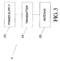
- a power supply 23 supplies power to a transmitter 24, the transmitter generating a signal within the jamming signal bandwidth 22.
- the transmitter 24 supplies the generated signal to an antenna 25 which, in turn, radiates the jamming signal.
- the jamming zone 5 is shown for illustrative purposes as circular, its actual configuration will depend upon the antenna configuration and the particular application.
- the jamming signal may be selected in a variety of other ways so as to prevent the tag receivers from responding to interrogation message signals from the surveillance transmitter 1, while not inhibiting the surveillance receiver 3 from responding to tag signals.
- system 10 can be a system which detects articles at the exit areas of a store or at any other areas in a store such as, for example, the checkout areas.
- the particular areas to be placed under surveillance will, in turn, dictate the region covered by the surveillance zone 2, as well as the particular locations for the surveillance receiver and transmitter equipment.
Landscapes
- Engineering & Computer Science (AREA)
- Physics & Mathematics (AREA)
- Computer Networks & Wireless Communication (AREA)
- Signal Processing (AREA)
- Computer Security & Cryptography (AREA)
- Electromagnetism (AREA)
- Microelectronics & Electronic Packaging (AREA)
- Automation & Control Theory (AREA)
- General Physics & Mathematics (AREA)
- Burglar Alarm Systems (AREA)
- Emergency Alarm Devices (AREA)
- Alarm Systems (AREA)
Applications Claiming Priority (2)
| Application Number | Priority Date | Filing Date | Title |
|---|---|---|---|
| US07/618,047 US5083111A (en) | 1990-11-26 | 1990-11-26 | Jamming apparatus for electronic article surveillance systems |
| US618047 | 1990-11-26 |
Publications (3)
| Publication Number | Publication Date |
|---|---|
| EP0487982A2 true EP0487982A2 (de) | 1992-06-03 |
| EP0487982A3 EP0487982A3 (en) | 1992-10-28 |
| EP0487982B1 EP0487982B1 (de) | 1999-07-07 |
Family
ID=24476116
Family Applications (1)
| Application Number | Title | Priority Date | Filing Date |
|---|---|---|---|
| EP91119408A Expired - Lifetime EP0487982B1 (de) | 1990-11-26 | 1991-11-14 | Störungsvorrichtung für elektronisches Artikelüberwachungssystem |
Country Status (7)
| Country | Link |
|---|---|
| US (1) | US5083111A (de) |
| EP (1) | EP0487982B1 (de) |
| JP (1) | JP3138030B2 (de) |
| AR (1) | AR247307A1 (de) |
| BR (1) | BR9104694A (de) |
| CA (1) | CA2048940A1 (de) |
| DE (1) | DE69131414T2 (de) |
Cited By (3)
| Publication number | Priority date | Publication date | Assignee | Title |
|---|---|---|---|---|
| WO1996020463A1 (fr) * | 1994-12-28 | 1996-07-04 | Roulleaux Robin Veronique | Procede et dispositif pour la detection, l'identification et la protection de biens notamment contre le vol |
| WO2001086608A3 (en) * | 2000-05-05 | 2002-05-30 | Sensormatic Electronics Corp | Eas system with wide exit coverage and reduced over-range |
| US8441534B2 (en) | 2005-04-29 | 2013-05-14 | Nxp B.V. | Electronic article surveillance system |
Families Citing this family (22)
| Publication number | Priority date | Publication date | Assignee | Title |
|---|---|---|---|---|
| WO1998018232A1 (en) * | 1996-10-23 | 1998-04-30 | Deropa (Proprietary) Limited | Cellular telephone jamming method and device |
| JP3470619B2 (ja) * | 1998-02-24 | 2003-11-25 | 三菱マテリアル株式会社 | 盗難検出用タグ |
| EP1254442A1 (de) * | 1999-12-15 | 2002-11-06 | Eident Limited | Etikett |
| US7050755B2 (en) * | 2002-01-24 | 2006-05-23 | Pctel Maryland, Inc. | Targeted mobile terminal communication blocker |
| US6757324B2 (en) * | 2002-07-18 | 2004-06-29 | Motorola, Inc. | Method and apparatus for detecting jamming signal |
| WO2005091889A2 (en) * | 2004-03-05 | 2005-10-06 | Seknion, Inc. | Method and apparatus for improving the efficiency and accuracy of rfid systems |
| EP1761790A2 (de) * | 2004-06-29 | 2007-03-14 | Symbol Technologies, Inc. | Systeme und verfahren zum testen von rfid-etiketts |
| US7889056B2 (en) * | 2005-10-31 | 2011-02-15 | Curio, Ltd. | RFID protection system, device, combination, and related methods |
| US8102243B2 (en) * | 2005-10-31 | 2012-01-24 | Curio Ltd. | RFID protection device, and related methods |
| US8451128B2 (en) | 2008-02-22 | 2013-05-28 | Xiao Hui Yang | Asset protection system |
| US8421628B2 (en) * | 2008-02-22 | 2013-04-16 | Xiao Hui Yang | Asset protection system |
| CA2768308A1 (en) * | 2009-06-15 | 2010-12-23 | Adel Odeh Sayegh | Article surveillance system |
| US8416060B2 (en) * | 2009-12-08 | 2013-04-09 | Symbol Technologies, Inc. | Method and device for reading radio frequency identification (RFID) tags |
| WO2011094387A1 (en) | 2010-01-29 | 2011-08-04 | Avery Dennison Corporation | Rfid/nfc panel and/or array used in smart signage applications and method of using |
| US10977965B2 (en) | 2010-01-29 | 2021-04-13 | Avery Dennison Retail Information Services, Llc | Smart sign box using electronic interactions |
| WO2013033522A1 (en) | 2011-09-01 | 2013-03-07 | Avery Dennison Corporation | Apparatus, system and method for consumer tracking |
| US8630908B2 (en) | 2011-11-02 | 2014-01-14 | Avery Dennison Corporation | Distributed point of sale, electronic article surveillance, and product information system, apparatus and method |
| CN104025129B (zh) * | 2012-09-10 | 2018-04-03 | 艾利丹尼森公司 | 用于防止nfc签条未授权转移的方法 |
| EP3214572B1 (de) | 2012-10-18 | 2020-01-29 | Avery Dennison Corporation | System und vorrichtung für nfc-sicherheit |
| CN110351693A (zh) | 2012-11-19 | 2019-10-18 | 艾利丹尼森公司 | 禁用未经授权的nfc安全系统和方法 |
| EP2987119A1 (de) | 2013-04-19 | 2016-02-24 | Curio, Ltd | Rfid-unterbrechungsvorrichtung und zugehörige verfahren |
| GB2568915A (en) * | 2017-11-30 | 2019-06-05 | Moran Humberto | Reshaping interrogation range |
Family Cites Families (10)
| Publication number | Priority date | Publication date | Assignee | Title |
|---|---|---|---|---|
| US4206453A (en) * | 1976-05-24 | 1980-06-03 | Williamson Robert D | Method and apparatus for electronic surveillance |
| DE3324956A1 (de) * | 1983-07-11 | 1985-01-24 | Robert Bosch Gmbh, 7000 Stuttgart | Schaltungsanordnung zur elektronischen ver- und entriegelung von sicherheitsanlagen |
| US4686513A (en) * | 1985-09-30 | 1987-08-11 | Sensormatic Electronics Corporation | Electronic surveillance using self-powered article attached tags |
| US4769631A (en) * | 1986-06-30 | 1988-09-06 | Sensormatic Electronics Corporation | Method, system and apparatus for magnetic surveillance of articles |
| DE3632624C1 (de) * | 1986-09-25 | 1988-03-10 | Balluff Gebhard Feinmech | Stoerfeldunempfindlicher Naeherungsschalter |
| US4821023A (en) * | 1988-01-07 | 1989-04-11 | Del Norte Technology, Inc. | Walk-through metal detector |
| US4866424A (en) * | 1988-01-11 | 1989-09-12 | Eg&G Astrophysics Research Corporation | Metal detector coil |
| US4888579A (en) * | 1988-09-16 | 1989-12-19 | Minnesota Mining And Manufacturing Company | False alarm minimization and direction determination methods |
| US4962369A (en) * | 1989-02-09 | 1990-10-09 | Marcia Israel | Merchandise security system utilizing RF transmitter |
| US5072213A (en) | 1989-02-09 | 1991-12-10 | Marcia Israel | Sensor for merchandise security system |
-
1990
- 1990-11-26 US US07/618,047 patent/US5083111A/en not_active Expired - Fee Related
-
1991
- 1991-08-12 CA CA002048940A patent/CA2048940A1/en not_active Abandoned
- 1991-08-20 AR AR91320520A patent/AR247307A1/es active
- 1991-10-30 BR BR919104694A patent/BR9104694A/pt not_active Application Discontinuation
- 1991-11-14 EP EP91119408A patent/EP0487982B1/de not_active Expired - Lifetime
- 1991-11-14 DE DE69131414T patent/DE69131414T2/de not_active Expired - Fee Related
- 1991-11-26 JP JP03310745A patent/JP3138030B2/ja not_active Expired - Lifetime
Cited By (5)
| Publication number | Priority date | Publication date | Assignee | Title |
|---|---|---|---|---|
| WO1996020463A1 (fr) * | 1994-12-28 | 1996-07-04 | Roulleaux Robin Veronique | Procede et dispositif pour la detection, l'identification et la protection de biens notamment contre le vol |
| FR2728991A1 (fr) * | 1994-12-28 | 1996-07-05 | Robin Veronique Roulleaux | Procede et dispositif pour la detection, l'identification et la protection de biens notamment contre le vol |
| WO2001086608A3 (en) * | 2000-05-05 | 2002-05-30 | Sensormatic Electronics Corp | Eas system with wide exit coverage and reduced over-range |
| AU2001259460B2 (en) * | 2000-05-05 | 2006-03-09 | Sensormatic Electronics Llc | EAS system with wide exit coverage and reduced over-range |
| US8441534B2 (en) | 2005-04-29 | 2013-05-14 | Nxp B.V. | Electronic article surveillance system |
Also Published As
| Publication number | Publication date |
|---|---|
| US5083111A (en) | 1992-01-21 |
| JPH04290198A (ja) | 1992-10-14 |
| AR247307A1 (es) | 1994-11-30 |
| CA2048940A1 (en) | 1992-05-27 |
| DE69131414D1 (de) | 1999-08-12 |
| EP0487982A3 (en) | 1992-10-28 |
| JP3138030B2 (ja) | 2001-02-26 |
| BR9104694A (pt) | 1992-06-23 |
| EP0487982B1 (de) | 1999-07-07 |
| DE69131414T2 (de) | 2000-03-02 |
Similar Documents
| Publication | Publication Date | Title |
|---|---|---|
| US5083111A (en) | Jamming apparatus for electronic article surveillance systems | |
| US5955950A (en) | Low noise signal generator for use with an RFID system | |
| MY109809A (en) | Detection of multiple articles | |
| US9824309B2 (en) | Mitigating adjacent RFID reader interference | |
| WO1998053343A2 (en) | Tagging system using motion detector | |
| GB1599120A (en) | Detection system | |
| GB1423418A (en) | Method and installation for the detection of a source generating electromagnetic oscillations | |
| US5533045A (en) | Automatic vehicle identification system, interrogator and responder included in the same | |
| EP1483752B1 (de) | Autophasensynchronisation für gepulste elektronische aritkelsicherungssysteme | |
| ATE265726T1 (de) | Sicherheitssystem zur durchgangsüberwachung von artikeln | |
| DK147169B (da) | Elektronisk sikkerhedssystem med interferensdetektering | |
| AU753617B2 (en) | Rfid system for detecting low power resonant tags | |
| CA2365566A1 (en) | Article monitoring apparatus and system | |
| US6130914A (en) | Communications system | |
| GB2218245A (en) | Radio tag alarm system | |
| WO1983001139A1 (en) | Long range wireless alarm monitoring system | |
| AU709450B2 (en) | System and method for simultaneous data link with multipurpose radar operations | |
| JP3119527B2 (ja) | 無線式識別装置 | |
| WO1991010206A1 (en) | Transmission system | |
| KR960704414A (ko) | 동적 무선 통신 시스템(dynamic radio communications system) | |
| KR100300264B1 (ko) | 전송장치, 전기적으로 부호화한 물품을 원격 식별하는 시스템 및방법 | |
| JP2840792B2 (ja) | 混信防止機能を有したワイヤレス送信器およびこれを用いたワイヤレス伝送制御システム | |
| JPH0591084A (ja) | Cdma通信方式における復号化装置 | |
| AU3715295A (en) | An electronic alarm system | |
| TH42395A (th) | ระบบรับและส่ง |
Legal Events
| Date | Code | Title | Description |
|---|---|---|---|
| PUAI | Public reference made under article 153(3) epc to a published international application that has entered the european phase |
Free format text: ORIGINAL CODE: 0009012 |
|
| AK | Designated contracting states |
Kind code of ref document: A2 Designated state(s): DE FR GB SE |
|
| RIN1 | Information on inventor provided before grant (corrected) |
Inventor name: DRUCKER, FRANK Inventor name: SZKLANY, CRAIG |
|
| PUAL | Search report despatched |
Free format text: ORIGINAL CODE: 0009013 |
|
| AK | Designated contracting states |
Kind code of ref document: A3 Designated state(s): DE FR GB SE |
|
| 17P | Request for examination filed |
Effective date: 19930428 |
|
| 17Q | First examination report despatched |
Effective date: 19970707 |
|
| GRAG | Despatch of communication of intention to grant |
Free format text: ORIGINAL CODE: EPIDOS AGRA |
|
| GRAG | Despatch of communication of intention to grant |
Free format text: ORIGINAL CODE: EPIDOS AGRA |
|
| GRAH | Despatch of communication of intention to grant a patent |
Free format text: ORIGINAL CODE: EPIDOS IGRA |
|
| GRAH | Despatch of communication of intention to grant a patent |
Free format text: ORIGINAL CODE: EPIDOS IGRA |
|
| GRAA | (expected) grant |
Free format text: ORIGINAL CODE: 0009210 |
|
| RAP1 | Party data changed (applicant data changed or rights of an application transferred) |
Owner name: SENSORMATIC ELECTRONICS CORPORATION |
|
| AK | Designated contracting states |
Kind code of ref document: B1 Designated state(s): DE FR GB SE |
|
| REF | Corresponds to: |
Ref document number: 69131414 Country of ref document: DE Date of ref document: 19990812 |
|
| ET | Fr: translation filed | ||
| PLBE | No opposition filed within time limit |
Free format text: ORIGINAL CODE: 0009261 |
|
| STAA | Information on the status of an ep patent application or granted ep patent |
Free format text: STATUS: NO OPPOSITION FILED WITHIN TIME LIMIT |
|
| 26N | No opposition filed | ||
| PGFP | Annual fee paid to national office [announced via postgrant information from national office to epo] |
Ref country code: FR Payment date: 20001018 Year of fee payment: 10 |
|
| PGFP | Annual fee paid to national office [announced via postgrant information from national office to epo] |
Ref country code: DE Payment date: 20001019 Year of fee payment: 10 |
|
| PGFP | Annual fee paid to national office [announced via postgrant information from national office to epo] |
Ref country code: GB Payment date: 20001020 Year of fee payment: 10 |
|
| PG25 | Lapsed in a contracting state [announced via postgrant information from national office to epo] |
Ref country code: GB Free format text: LAPSE BECAUSE OF NON-PAYMENT OF DUE FEES Effective date: 20011114 |
|
| PG25 | Lapsed in a contracting state [announced via postgrant information from national office to epo] |
Ref country code: SE Free format text: LAPSE BECAUSE OF NON-PAYMENT OF DUE FEES Effective date: 20011115 |
|
| REG | Reference to a national code |
Ref country code: GB Ref legal event code: IF02 |
|
| EUG | Se: european patent has lapsed |
Ref document number: 91119408.2 |
|
| PG25 | Lapsed in a contracting state [announced via postgrant information from national office to epo] |
Ref country code: DE Free format text: LAPSE BECAUSE OF NON-PAYMENT OF DUE FEES Effective date: 20020702 |
|
| PG25 | Lapsed in a contracting state [announced via postgrant information from national office to epo] |
Ref country code: FR Free format text: LAPSE BECAUSE OF NON-PAYMENT OF DUE FEES Effective date: 20020730 |
|
| REG | Reference to a national code |
Ref country code: FR Ref legal event code: ST |
|
| REG | Reference to a national code |
Ref country code: FR Ref legal event code: ST |
|
| PGFP | Annual fee paid to national office [announced via postgrant information from national office to epo] |
Ref country code: SE Payment date: 20101126 Year of fee payment: 20 |