EP0487530B1 - Image transfer apparatus and method - Google Patents
Image transfer apparatus and method Download PDFInfo
- Publication number
- EP0487530B1 EP0487530B1 EP90907505A EP90907505A EP0487530B1 EP 0487530 B1 EP0487530 B1 EP 0487530B1 EP 90907505 A EP90907505 A EP 90907505A EP 90907505 A EP90907505 A EP 90907505A EP 0487530 B1 EP0487530 B1 EP 0487530B1
- Authority
- EP
- European Patent Office
- Prior art keywords
- intermediate transfer
- layer
- transfer member
- image
- transfer
- Prior art date
- Legal status (The legal status is an assumption and is not a legal conclusion. Google has not performed a legal analysis and makes no representation as to the accuracy of the status listed.)
- Expired - Lifetime
Links
Images


Classifications
-
- G—PHYSICS
- G03—PHOTOGRAPHY; CINEMATOGRAPHY; ANALOGOUS TECHNIQUES USING WAVES OTHER THAN OPTICAL WAVES; ELECTROGRAPHY; HOLOGRAPHY
- G03G—ELECTROGRAPHY; ELECTROPHOTOGRAPHY; MAGNETOGRAPHY
- G03G5/00—Recording members for original recording by exposure, e.g. to light, to heat, to electrons; Manufacture thereof; Selection of materials therefor
- G03G5/005—Materials for treating the recording members, e.g. for cleaning, reactivating, polishing
-
- G—PHYSICS
- G03—PHOTOGRAPHY; CINEMATOGRAPHY; ANALOGOUS TECHNIQUES USING WAVES OTHER THAN OPTICAL WAVES; ELECTROGRAPHY; HOLOGRAPHY
- G03G—ELECTROGRAPHY; ELECTROPHOTOGRAPHY; MAGNETOGRAPHY
- G03G15/00—Apparatus for electrographic processes using a charge pattern
- G03G15/14—Apparatus for electrographic processes using a charge pattern for transferring a pattern to a second base
- G03G15/16—Apparatus for electrographic processes using a charge pattern for transferring a pattern to a second base of a toner pattern, e.g. a powder pattern, e.g. magnetic transfer
- G03G15/1605—Apparatus for electrographic processes using a charge pattern for transferring a pattern to a second base of a toner pattern, e.g. a powder pattern, e.g. magnetic transfer using at least one intermediate support
- G03G15/161—Apparatus for electrographic processes using a charge pattern for transferring a pattern to a second base of a toner pattern, e.g. a powder pattern, e.g. magnetic transfer using at least one intermediate support with means for handling the intermediate support, e.g. heating, cleaning, coating with a transfer agent
-
- G—PHYSICS
- G03—PHOTOGRAPHY; CINEMATOGRAPHY; ANALOGOUS TECHNIQUES USING WAVES OTHER THAN OPTICAL WAVES; ELECTROGRAPHY; HOLOGRAPHY
- G03G—ELECTROGRAPHY; ELECTROPHOTOGRAPHY; MAGNETOGRAPHY
- G03G15/00—Apparatus for electrographic processes using a charge pattern
- G03G15/14—Apparatus for electrographic processes using a charge pattern for transferring a pattern to a second base
- G03G15/16—Apparatus for electrographic processes using a charge pattern for transferring a pattern to a second base of a toner pattern, e.g. a powder pattern, e.g. magnetic transfer
- G03G15/1605—Apparatus for electrographic processes using a charge pattern for transferring a pattern to a second base of a toner pattern, e.g. a powder pattern, e.g. magnetic transfer using at least one intermediate support
- G03G15/162—Apparatus for electrographic processes using a charge pattern for transferring a pattern to a second base of a toner pattern, e.g. a powder pattern, e.g. magnetic transfer using at least one intermediate support details of the the intermediate support, e.g. chemical composition
-
- G—PHYSICS
- G03—PHOTOGRAPHY; CINEMATOGRAPHY; ANALOGOUS TECHNIQUES USING WAVES OTHER THAN OPTICAL WAVES; ELECTROGRAPHY; HOLOGRAPHY
- G03G—ELECTROGRAPHY; ELECTROPHOTOGRAPHY; MAGNETOGRAPHY
- G03G15/00—Apparatus for electrographic processes using a charge pattern
- G03G15/14—Apparatus for electrographic processes using a charge pattern for transferring a pattern to a second base
- G03G15/16—Apparatus for electrographic processes using a charge pattern for transferring a pattern to a second base of a toner pattern, e.g. a powder pattern, e.g. magnetic transfer
- G03G15/169—Apparatus for electrographic processes using a charge pattern for transferring a pattern to a second base of a toner pattern, e.g. a powder pattern, e.g. magnetic transfer with means for preconditioning the toner image before the transfer
-
- G—PHYSICS
- G03—PHOTOGRAPHY; CINEMATOGRAPHY; ANALOGOUS TECHNIQUES USING WAVES OTHER THAN OPTICAL WAVES; ELECTROGRAPHY; HOLOGRAPHY
- G03G—ELECTROGRAPHY; ELECTROPHOTOGRAPHY; MAGNETOGRAPHY
- G03G5/00—Recording members for original recording by exposure, e.g. to light, to heat, to electrons; Manufacture thereof; Selection of materials therefor
- G03G5/02—Charge-receiving layers
- G03G5/04—Photoconductive layers; Charge-generation layers or charge-transporting layers; Additives therefor; Binders therefor
-
- G—PHYSICS
- G03—PHOTOGRAPHY; CINEMATOGRAPHY; ANALOGOUS TECHNIQUES USING WAVES OTHER THAN OPTICAL WAVES; ELECTROGRAPHY; HOLOGRAPHY
- G03G—ELECTROGRAPHY; ELECTROPHOTOGRAPHY; MAGNETOGRAPHY
- G03G5/00—Recording members for original recording by exposure, e.g. to light, to heat, to electrons; Manufacture thereof; Selection of materials therefor
- G03G5/14—Inert intermediate or cover layers for charge-receiving layers
- G03G5/142—Inert intermediate layers
Definitions
- the present invention relates to image transfer techniques and apparatus for use in liquid toner electrostatic imaging using an intermediate transfer member.
- pressures used in offset printing are generally not specified. However, pressures are indicated to be in the general vicinity of 100-150 lb./sq. in. in the above reference and in U. S. Patent 3,983,287.
- European Patent Publication 0 176 143 Al describes a powder toner copying machine utilizing an intermediate transfer member in which the pressure and deformation at first transfer is less than at second transfer.
- Japanese patent publication 62-134673 describes a powder toner imaging system utilizing an intermediate transfer member in which the pressure is greater at second transfer than at first transfer.
- U.S. Patent 4,912,514 describes a powder toner imaging system having a heated intermediate transfer belt where, in one embodiment the heater is formed of enlongate elements and the belt includes a silicone rubber layer.
- U.S. Patent 4,708,460 describes a liquid toner imaging system in which an intermediate transfer member is used.
- the present invention seeks to provide apparatus and techniques for improved electrostatic image transfer using an intermediate transfer member.
- imaging apparatus comprising:
- the resilient layer is situated between the heater and the transfer surface.
- the intermediate transfer blanket comprises a conductive layer operative to apply an electric field to the image to enhance transfer of the liquid toner image from the image bearing surface to the intermediate transfer member.
- the intermediate transfer member comprises a second compressible layer.
- the heating layer is disposed intermediate the compressible layer and the second compressible layer.
- Fig. 1 illustrates electrostatic imaging apparatus constructed and operative in accordance with a preferred embodiment of the present invention.
- This and other embodiments of the invention are described by way of example for apparatus utilizing liquid toner with negatively charged toner particles, and for a write-white system.
- the magnitudes and or the polarities of the voltages may be adjusted as is well known in the art.
- the toner of Example 1 of U.S. Patent 4,794,651 the disclosure of which is hereby referred to, is employed, but a variety of liquid toner types may be used in the practice of the invention.
- the apparatus of Fig. 1 comprises a drum 10 arranged for rotation about an axle 12 in a direction generally indicated by arrow 14.
- the drum 10 is formed with a cylindrical photoconductor surface 16.
- a corona discharge device 18 is operative to generally uniformly charge the photoconductor surface 16 with a positive charge.
- an exposure unit including a lens 20, which focuses a desired image onto the charged photoconductor surface 16, there by selectively discharging the photoconductor surface and producing an electrostatic latent image thereon.
- Lens 20 may be the lens of a photocopier, as illustrated. Alternatively the latent image may be formed by a laser scanner.
- photoconductor surface 16 passes a typically positively charged, rotating roller 26, preferably rotating in a direction indicated by an arrow 28.
- a typically positively charged, rotating roller 26 preferably rotating in a direction indicated by an arrow 28.
- the spatial separation of the roller 26 from the photoconductor surface 16 is about 50 microns.
- the voltage on roller 26 is intermediate the voltages of the latent image areas and of the background areas on the photoconductor surface 16.
- Typical voltages are: roller 26: +300 to +500 V, background area: +50 V and latent image areas: up to +1000 V.
- roller 26 rotating in the direction indicated by arrow 28, functions as a metering roller and reduces the thickness of liquid carrier on the photoconductor surface 16, as is known in the art.
- the photoconductor surface 16, after passing the roller 26, should be relatively free of pigmented toner particles except in the region of the latent image.
- Rigidizing roller 30 is preferably formed of a resilient polymeric material, such as the conductive resilient polymeric materials described in either or both of U.S. Patents 3,959,574 and 3,863,603, the disclosures of which are hereby referred to. Roller 30 is preferably maintained in contacting and preferably pressured relationship with the photoconductor surface 16.
- the biased squeegee described in U. S. Patent 4,286,039, the disclosure of which is hereby referred to is used as the roller 30.
- a corona discharge takes place and a current of approximately 50 - 100 microamperes for a drum width of 30 cm, flows from the squeegee.
- Roller 30 repels negatively charged pigmented toner particles and causes them to more closely approach the image areas of the photoconductor surface 16, thus compressing and rigidizing the toner image thereon.
- an intermediate transfer member 40 Downstream of rigidizing roller 30 there is provided an intermediate transfer member 40, which rotates, as shown by arrow 41, in a sense opposite to that of drum 10, and is operative for receiving the toner image from surface 16 and for transferring the toner image to a receiving substrate 42, such as paper, which is supported by a roller 43.
- intermediate transfer member 40 is configured and mounted with respect to drum 10 so as to provide first transfer engagement between intermediate transfer member 40 and image bearing photoconductor surface 16 for transfer of an image from surface 16 to the intermediate transfer member 40 at a first pressure, thereby producing radial deformation of the intermediate transfer member to a first deformation degree.
- intermediate transfer member 40, substrate 42 and roller 43 are preferably such as to provide second transfer engagement between intermediate transfer member 40 and substrate 42 for transfer of the image from intermediate transfer member 40 to substrate 42 at a second pressure, which exceeds the first pressure by a first multiple, producing radial deformation of the intermediate transfer member to a second deformation degree which exceeds the first deformation degree by a second multiple substantially less than the first multiple.
- an intermediate transfer member characterized in that deformation thereof increases less than linearly with the application of increased pressure thereto.
- the structure of intermediate transfer members in accordance with preferred embodiments of the invention is described hereinbelow in detail.
- Transfer of the image to intermediate transfer member 40 is preferably facilitated by providing electrification of the intermediate transfer member 40 to a voltage opposite that of the charged particles, although other methods known in the art may be employed. Subsequent transfer of the image to substrate 42 is preferably facilitated by heat and pressure, although other methods known in the art may be employed.
- the photoconductor surface 16 is engaged by a cleaning roller assembly 50, including a pair of rollers 52, which typically rotate in opposite directions, and a nozzle 54.
- Cleaning roller assembly 50 is operative to scrub and clean surface 16.
- a cleaning material such as liquid developer, may be supplied to the assembly 50 via nozzle 54.
- a suitable cleaning assembly is shown and described in U.S. Patent 4,439,035, the disclosure of which is hereby referred to. Any residual charge left on the photoconductor surface 16 may be removed by flooding the photoconductor surface 16 with light from a lamp 58.
- FIG. 2 illustrates electrophotographic imaging apparatus constructed and operative in accordance with another preferred embodiment of the present invention.
- the apparatus of Fig. 2 shares many common elements with that of Fig. 1. These elements are indicated by identical reference numerals, and for the sake of conciseness are not described herein a second time.
- Fig. 2 differs from that of Fig. 1 in that a belt-type intermediate transfer member 70 is employed instead of the roller type member 40 in the embodiment of Fig. 1.
- Belt-type intermediate transfer members are well known in the art and are described, inter alia, in U.S. Patents 3,893,761, 4,684,238 and 4,690,539, the disclosures of which are hereby referred to.
- Intermediate transfer member 70 is preferably charged so as to provide electrophoretic transfer thereto of the image from the photoconductor surface 16.
- the efficiency of electrophoretic transfer of the image is generally enhanced by increasing the potential difference between photoconductor surface 16 and intermediate transfer member 70. Increase in the potential difference between the photoconductor surface 16 and the intermediate transfer member 70 is limited, however, by the danger of severe electrical breakdown, which increases with an increase in potential difference.
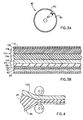
- FIG. 3A conceptually illustrates an intermediate transfer member 40 comprising a drum 80 having a generally cylindrical surface over which is tensioned a multi-layer intermediate transfer blanket 82, which is supported and tensioned by a blanket lockup mechanism 84.
- the electrical connections to the various voltage bearing portions of intermediate transfer blanket 82 are not shown, it being understood that they are achieved in a conventional manner using rotating contacts.
- a preferred embodiment of multi-layer intermediate transfer blanket 82 is illustrated in Fig. 3B and comprises a substrate (backing layer) 90 with high temperature capabilities, preferably formed of Kapton (DuPont) polyimide film of thickness about 100 microns.
- a blanket heater 92 preferably comprising a meandering ribbon conductor of Nichrome (Trademark; an alloy of Driver Harris Org.) in a sandwich of Kapton.
- Blanket heater 92 has a total thickness of about 250 microns.
- blanket heater 92 Normally one surface of blanket heater 92 has a slightly raised pattern due to the presence of the ribbon. Accordingly, it is preferable to arrange the blanket heater 92 such that the surface having the slightly raised pattern lies facing substrate 90.
- Blanket heater 92 in conjunction with the rest of the intermediate transfer blanket 82, operates to improve transfer of the image to the final substrate by heating the toner image.
- the surface of the blanket should be heated to a temperature above the solvation temperature of the toner image, i.e. above the temperature at which the toner particles become tacky to the final substrate.
- the blanket heater is preferably operative to heat the image on the intermediate transfer member to about 100-110° C.
- the top of the blanket heater 92 is preferably attached to an approximately 100 micron thick aluminum foil 93.
- This foil also provides electromagnetic shielding of the image transfer regions of the imaging apparatus from interference produced by AC currents used to heat the blanket 92.
- the width of the Nichrome ribbon is chosen such that the ribbon covers a major portion, preferably over 80%, of the blanket, to ensure even heating thereof.
- a three part sponge assembly layer 94 Disposed over foil 93 is a three part sponge assembly layer 94, including a layer 96 typically formed of Kapton, typically of thickness 100 microns, a sponge layer 98, typically of thickness 300 microns and a fabric layer 100, typically formed of NOMEX (DuPont) and being typically of thickness 350 microns.
- the total sponge assembly layer thickness is typically 800 microns.
- Nomex is basically an aromatic polyamide and chars at 420°C.
- the assembly layer 94 is preferably formed by blending the following materials, which form the sponge layer 98, in the following proportions, in a two roll mill: a. Fluorosilicone (FSE-2080 General Electric) 78.39% b. Silicone (Silastic 4-2735 Dow Corning) 11.71% c. Blowing Agent (#9038 Rhone Poulenc) 9.00% d. Cross-Linker (Di Cumyl Peroxide) 0.90%
- the blended material is formed into the assembly layer 94 by calendering between the fabric layer 100 and the Kapton layer 96 as illustrated in Fig. 4.
- the total thickness of assembly layer 94 is typically about 670 microns after calendering.
- the assembly layer 94 is then preferably cured for 10 minutes under nitrogen at 170° C and preferably in a jig to control the total swelling thereof to a final total thickness of about 800 microns. After the curing, the assembly layer 94 preferably undergoes a post-cure at 200° C for four hours.
- the sponge assembly layer 94 allows conformity between surface 16 and intermediate transfer member 40 at the first transfer at a relatively low pressure, such as 100 - 500 gm/cm 2 at a temperature of about 100-110° C, with relatively low deformation, such as 30 - 200 microns, overcoming any surface unevenness of the mating surfaces.
- sponge assembly layer 94 is further characterized in that it undergoes relatively high pressure, such as 2000 to 4000 gm/cm 2 at the second transfer with proportionately low deformation, greater then that at first transfer, preferably about 250 microns.
- the pressure at the first transfer surface can be increased up to about 500 gm/cm 2 , without substantial image degradation.
- a blanket 102 typically of about 1200 microns thickness.
- Blanket 102 typically includes a layer 104 of relatively stiff sponge, over which is formed a layer 106 of nitrilic rubber. Blanket 102 may be produced by removing the fabric layer from the three-ply Vulcan 714 offset printing blanket commercially available from Reeves Brothers, Inc.
- Over printing blanket 102 there is provided a 2-3 micron thick layer 108 of nitrocellulose loaded with carbon black to provide a conductive layer for the high voltage applied to the intermediate transfer member.
- This layer has an end to end resistance of about 20 - 30 kohm, but since the current drawn to the drum is only 50 - 100 microamperes, the voltage drop on the layer is less than 3 volts out of the applied voltage of 500 - 600 volts.
- An outer layer 110 typically comprises a 2 - 3 micron thick layer of silicone rubber, such as Syl-Off 294, which acts as a release layer.
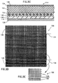
- a blanket 114 in accordance with an alternative preferred embodiment of the invention is shown conceptually in cross section in Fig. 3C.
- the lowest level of the blanket is a Kapton layer 116, typically 100 microns thick, which is similar to layer 96 of Fig. 3B.
- the next layer is a sponge layer 118, functionally similar to sponge layer 98 shown in Fig. 3B and typically 300 microns thick.
- a heater 120 Situated above layer 118 is a heater 120, with typical thickness 650 microns, whose structure and manufacture are described hereinbelow.
- An acrylic rubber layer 122 is formed onto the heater 120 and preferably penetrates thereinto.
- a conducting layer 124 and a release layer 126 complete the blanket.
- Additional spacer material 128, typically of Kapton, may be added below the blanket, if additional blanket thickness is required. Alternatively the Kapton layer 116 may be thicker than the indicated thickness.
- heater 120 may be formed by weaving heater wire 130 forming the woof and twisted thread 132 as the warp.
- wire 130 is formed of a 300 micron diameter copper core with a 10 micron lacquer coating, for a total diameter of 320 microns.
- Thread 132 is preferably of twisted Nomex thread with a nominal diameter of 320 microns.
- connection wires 134 for energizing the heater are extensions of the heater wires 130.
- a Nomex cloth extension 136 is provided beyond each end of the heater portion of the heater 120.
- the unconventional structure of the blanket heater 120 of Figs. 3D and 3E enables its placement over sponge layer 118. It is noted that heater 92 of the embodiment illustrated in Fig. 3B is placed below the sponge layer 98. Since heater 92 is relatively stiff in both the circumferential and the axial directions, placement of the heater 92 above the sponge layer would substantially shield the blanket-photoconductor and blanket-final substrate image transfer interfaces from the compression properties of the sponge assembly 94.
- Heater 120 is stiff in the axial direction, but is pliable in the circumferential direction and thus transmits the pressure at the respective interfaces to the sponge layer. Placing the heater closer to the transfer surface allows for a lower heater temperature for the same surface temperature, and allows the sponge layer to be much cooler.
- the pressure along lines in the axial direction is substantially constant compared to the variations in the circumferential direction; it would be perfectly constant were the transfer surfaces perfect and the mechanical tolerances equal to zero. The imperfections and tolerances cause some small minor variations in deformation and hence in pressure along the axial lines.
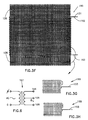
- FIG. 3F and 3G An alternative preferred heater 150 is shown in Figs. 3F and 3G.
- two inputs 151 and 152 are at the same end of the heater wires and the wires are threaded in a paired spaced relationship as shown in Figs. 3F and 3G.
- Additional input 153 is electrically connected to the other end of the heater such that the current path between inputs 151 and 153 is of substantially the same length as that of the current path between inputs 152 and 153.
- the heater 150 is preferably energized with the circuit of Fig. 6, wherein the input to a transformer 157 is an AC voltage and a pair of output terminals 154 and 156 of transformer 157 are at the same voltage and at opposite phases with respect to a third terminal 155. Terminals 154, 155 and 156 are electrically insulated from the AC input.
- heater 150 is incorporated in a blanket, and installed in the apparatus of Fig. 1.
- Terminals 154 and 156 are electrically connected to inputs 151 and 152, and additional input 153 is connected to terminal 155.
- the wires can be "crossed" at each reversal of the wire direction (at the edges of the heater). One such crossing is shown in Fig. 3H.
- wire 153 and terminal 155 may be externally electrically connected to the bias layer 124.
- wire 153 and terminal 153 may be connected to a source of high voltage in order to provide a field at the transfer regions and layer 124 may be omitted.
- a substantially higher voltage would be required to provide the field due to the greater distance of the heater from the transfer surface.
- FIG. 3I An alternative preferred heater 160 is shown in Fig. 3I.
- the wire and thread are woven in a similar manner to that of the embodiment shown in Fig. 3D.
- Two connection wires 162 and 164 for energizing the heater are extensions of the heater wire and an additional wire 168 is electrically connected to the center of the length of wire used to form the heater. In operation the heater is energized by connecting wires 162 and 164 to terminals 154 and 156 respectively, and connecting wire 168 to terminal 155.
- Layer 122 preferably has the following properties:
- Blanket 114 is preferably manufactured using the following process, although any other suitable manufacturing method may be used:
- HYTEMP 4051 Acrylic rubber compound manufactured by B.F. Goodrich 100 parts by weight of HYTEMP 4051 Acrylic rubber compound manufactured by B.F. Goodrich is mixed in a two roll mill with 15 parts of very fine silica, 4 parts sodium stearate and 2 parts NPC-50 crosslinker, until the mixture is smooth. The silica is added to increase the electrical resistivity, mechanical cohesiveness and strength of the final polymer.
- a heater 120 is placed in a mold coated with silicone oil, and is covered with the rubber/silica mixture. The mixture is cured in the mold to a final thickness of 1500 microns at a temperature of 180°C for 15 minutes. The mold is cooled and the resulting sheet is removed. It will be appreciated that this sheet comprises heater 120 and rubber layer 122 formed into an integral unit due to the filling of the heater by the rubber/silica mixture before curing.
- HYTEMP 4051 Acrylic rubber compound manufactured by B.F. Goodrich is mixed in a two roll mill with 15 parts of very fine silica, 4 parts of sodium stearate, 2 parts of NPC-50 crosslinker and 11 to 33 parts by weight of Blowing Agent (#9038 Rhone Poulenc) until the mixture is smooth.
- the silica is added to increase the cohesiveness of the sponge.
- 1 part of the mixture is mixed with preferably 2 parts of a solvent, preferably acetone or MEK, in order to reduce its viscosity.
- the blended material is calendered between the double layer 120 and 122 and the Kapton layer 116 essentially as described above and as illustrated in Fig. 4 for the manufacture of sponge layer 98.
- the total thickness of the resulting multilayer sheet 118, 122, 120 and 116 after calendering will depend on the amount of blowing agent used and can be determined experimentally.
- the triple layer is cured, preferably in a jig, to control the total swelling thereof, at a temperature of 180°C for 15 minutes.
- the mold is cooled and the resulting sheet is removed. It will be appreciated that this sheet comprises all four layers formed into an integral unit.
- the Kapton layer 116 can be replaced by a Nomex cloth layer, since the acrylic rubber layers together with a Nomex cloth layer appear to give sufficient structural strength to the blanket.
- HYTEMP 4051 15 parts of HYTEMP 4051, 100 parts of MEK (methylmetacrilate), 6 parts of carbon black (Printex XE-2 manufactured by Degussa) and 2 parts of NPC-50 cross-linker are mixed in a cooled ball attritor for 12 hours.
- This material is wire coated onto the surface of layer 122 and cured at 150°C for 15 minutes to form an approximately 2 micron thick conducting layer with a resistance of between 10-100 kohm/square, preferably 30-50 kohm/square, bonded to layer 122.
- Post curing of the HYTEMP 4051 is not part of the process as recommended by the manufacturer. however it has been found that the stability of the material under compression cycling at operating temperature was improved by the addition of a 180° C, 12 hour post curing step.
- Syl-off 294 100 parts of Syl-off 294 is diluted 1:1 with Isopar L. 15 parts of Syl-off 297 ancorning agent and 5 parts of Dow Corning 176 cross-linker are added to the mixture. This mixture is wire coated on to the surface of conducting layer 124 and air cured at 110°C for 10 minutes to provide a 5-6 micron thick layer.
- Fig. 5 is a graph which illustrates the approximate desired pressure/deformation characteristics of the intermediate transfer member structures shown in Fig. 3B-3I, under ordinary use conditions, in intermediate transfer apparatus constructed and operative according to a preferred embodiment of the present invention.
- the invention is illustrated herein with examples employing a single developer station.
- the invention is especially useful in imaging systems with a multiplicity of development stations preferably with different color liquid developers, or with a single station in which the liquid developer is changed between colors.
- each individual color image may be transferred to the final substrate from the ITM individually, or the colored images may be transferred sequentially to the ITM and then transferred to the substrate together.
- Color imaging equipment is described in U. S. Patents 4,788,572; 4,690,539 and 3,900,003, the disclosure of which documents are hereby referred to.
Abstract
Description
- The present invention relates to image transfer techniques and apparatus for use in liquid toner electrostatic imaging using an intermediate transfer member.
- The use of an intermediate transfer member in electrostatic imaging is well known in the art.
- Various types of intermediate transfer members are known and are described, for example in U.S. Patents 3,862,848, 4,684,238, 4,690,539 and 4,531,825.
- Belt-type intermediate transfer members for use in electrophotography are known in the art and are described, inter alia, in U.S. Patents 3,893,761, 4,684,238 and 4,690,539.
- In both liquid and powder toner imaging systems employing intermediate transfer members it is known to heat the toner images on the intermediate transfer member before transfer to the final substrate. In U. S. Patent 4,708,460 a liquid toner image is heated by radiant heat from a heater external to the transfer member in order to evaporate the liquid carrier and to melt the solid toner before transfer. In U. S. Patent 4,518,976 there is described a belt image transfer system, wherein the belt is heated by a heating roller, provided at the back of the belt, during transfer from the belt to the final substrate. In U. S. Patent 4,585,319 a radiant heater in the center of a drum ITM is used to heat the ITM.
- The use of intermediate transfer members is well known in the printing art. In offset printing an image formed of a viscous ink is transferred from a first drum to a second drum prior to transfer to the final substrate. It has been recognized that the pressures between the various drums and against the final substrate are important to the quality of the final print.
- Two types of offset blankets are generally available, consistent with the ink characteristics. Conventional printing blankets are relatively stiff and have provided little leeway for packing error. Compressible blankets are made with varying compressibilities, with typical curves shown for example on page 33 of "Web Offset-Press Operating", published by Graphic Arts Technical Foundation, Pittsburgh, PA, 1984.
- The pressures used in offset printing are generally not specified. However, pressures are indicated to be in the general vicinity of 100-150 lb./sq. in. in the above reference and in U. S. Patent 3,983,287.
-
European Patent Publication 0 176 143 Al describes a powder toner copying machine utilizing an intermediate transfer member in which the pressure and deformation at first transfer is less than at second transfer. Japanese patent publication 62-134673 describes a powder toner imaging system utilizing an intermediate transfer member in which the pressure is greater at second transfer than at first transfer. - U.S. Patent 4,912,514 describes a powder toner imaging system having a heated intermediate transfer belt where, in one embodiment the heater is formed of enlongate elements and the belt includes a silicone rubber layer. U.S. Patent 4,708,460 describes a liquid toner imaging system in which an intermediate transfer member is used.
- The present invention seeks to provide apparatus and techniques for improved electrostatic image transfer using an intermediate transfer member.
- There is therefore provided imaging apparatus comprising:
- an image bearing surface;
- means for forming a toner image, preferably a liquid toner image, on the image bearing surface;
- an intermediate transfer member operative for transfer of the toner image from the image bearing surface to a transfer surface of the intermediate transfer member and for subsequent transfer to a substrate,
- In a prefered embodiment of the invention the intermediate transfer blanket comprises:
- a transfer surface for operative engagement with the first and second surfaces;
- a resilient layer;
- a sponge layer which is softer than the resilient layer; and
- an area heater disposed between the relatively compliant sponge layer and the resilient layer.
- Preferably the resilient layer is situated between the heater and the transfer surface.
- In a preferred embodiment of the invention the intermediate transfer blanket comprises a conductive layer operative to apply an electric field to the image to enhance transfer of the liquid toner image from the image bearing surface to the intermediate transfer member.
- In a preferred embodiment of the invention the intermediate the intermediate transfer blanket comprises:
- an outward facing transfer surface;
- a compressible layer;
- a backing layer; and
- a heating layer disposed intermediate the backing layer and the transfer surface.
- Preferably, the intermediate transfer member comprises a second compressible layer. Preferably, the heating layer is disposed intermediate the compressible layer and the second compressible layer.
- In a preferred embodiment of the invention the imaging apparatus comprises:
- means for providing first transfer engagement between the intermediate transfer member and the image bearing surface for transfer of the toner image from the image bearing surface to the intermediate transfer member at a first pressure, producing deformation of the intermediate transfer member to a first deformation degree;
- means for providing second transfer engagement between the intermediate transfer member and the substrate for transfer of the toner image from the intermediate transfer member to the substrate at a second pressure, producing deformation of the intermediate transfer member to a second deformation degree, wherein
- the ratio of the second pressure to the first pressure is substantially greater than the ratio of the second deformation degree to the first deformation degree.
- The present invention will be understood and appreciated more fully from the following detailed description, taken in conjunction with the drawings in which:
- Fig. 1 is a simplified sectional illustration of electrostatic imaging apparatus constructed and operative in accordance with a preferred embodiment of the present invention;
- Fig. 2 is a simplified sectional illustration of electrostatic imaging apparatus constructed and operative in accordance with another preferred embodiment of the present invention;
- Fig. 3A is a simplified, conceptual, sectional illustration of an intermediate transfer member constructed and operative in accordance with a preferred embodiment of the present invention;
- Fig. 38 is a simplified, conceptual, sectional illustration of a portion of a preferred embodiment of the intermediate transfer member of Fig. 3A;
- Fig. 3C is a simplified, conceptual, sectional illustration of a portion of a second preferred embodiment of the intermediate transfer member of Fig. 3A;
- Fig. 3D is an illustration of a preferred heater for the intermediate transfer member;
- Fig. 3E is a detailed illustration of a portion of the heater of Fig. 3D;
- Fig. 3F is an illustration of another preferred heater for the intermediate transfer member;
- Fig. 3G is a detailed illustration of a portion of the heater of Fig. 3F;
- Fig. 3H is a detailed illustration of a portion of an alternative to that of Fig. 3F;
- Fig. 3I is an illustration of another preferred heater for the intermediate transfer member;
- Fig. 4 is a simplified sectional illustration of the manufacture of part of the apparatus of Figs. 3A and 3B;
- Fig. 5 is a graphical illustration of the relationship between pressure and deformation of the apparatus of Fig. 3B; and
- Fig. 6 is a schematic illustration of a preferred circuit for energizing the heaters of Figs. 3F-3I.
- Reference is now made to Fig. 1, which illustrates electrostatic imaging apparatus constructed and operative in accordance with a preferred embodiment of the present invention. This and other embodiments of the invention are described by way of example for apparatus utilizing liquid toner with negatively charged toner particles, and for a write-white system. For positively charged toner particles and/or for a write-black system the magnitudes and or the polarities of the voltages may be adjusted as is well known in the art. In a preferred embodiment of the invention the toner of Example 1 of U.S. Patent 4,794,651 the disclosure of which is hereby referred to, is employed, but a variety of liquid toner types may be used in the practice of the invention.
- As in conventional electrophotographic systems, the apparatus of Fig. 1 comprises a
drum 10 arranged for rotation about anaxle 12 in a direction generally indicated byarrow 14. Thedrum 10 is formed with acylindrical photoconductor surface 16. - A
corona discharge device 18 is operative to generally uniformly charge thephotoconductor surface 16 with a positive charge. Continued rotation of thedrum 10 brings the chargedphotoconductor surface 16 into image receiving relationship with an exposure unit including alens 20, which focuses a desired image onto the chargedphotoconductor surface 16, there by selectively discharging the photoconductor surface and producing an electrostatic latent image thereon.Lens 20 may be the lens of a photocopier, as illustrated. Alternatively the latent image may be formed by a laser scanner. - Continued rotation of the
drum 10 brings the chargedphotoconductor surface 16 bearing the electrostatic latent image into operative association with adevelopment unit 22, includingdevelopment electrodes 24, which is operative to apply a liquid developer comprising carrier liquid and toner particles to the photoconductor surface to develop the electrostatic latent image thereon. - In accordance with a preferred embodiment of the invention, following application of toner to
photoconductor surface 16,photoconductor surface 16 passes a typically positively charged, rotatingroller 26, preferably rotating in a direction indicated by anarrow 28. Typically the spatial separation of theroller 26 from thephotoconductor surface 16 is about 50 microns. - Preferably, the voltage on
roller 26 is intermediate the voltages of the latent image areas and of the background areas on thephotoconductor surface 16. Typical voltages are: roller 26: +300 to +500 V, background area: +50 V and latent image areas: up to +1000 V. - It is appreciated that
roller 26, rotating in the direction indicated byarrow 28, functions as a metering roller and reduces the thickness of liquid carrier on thephotoconductor surface 16, as is known in the art. - In any event, the
photoconductor surface 16, after passing theroller 26, should be relatively free of pigmented toner particles except in the region of the latent image. - Downstream of
roller 26 there is preferably provided arigidizing roller 30.Rigidizing roller 30 is preferably formed of a resilient polymeric material, such as the conductive resilient polymeric materials described in either or both of U.S. Patents 3,959,574 and 3,863,603, the disclosures of which are hereby referred to.Roller 30 is preferably maintained in contacting and preferably pressured relationship with thephotoconductor surface 16. - In a preferred embodiment of the invention, the biased squeegee described in U. S. Patent 4,286,039, the disclosure of which is hereby referred to, is used as the
roller 30. A negative voltage of about 1000 to 2000 Volts, preferably about 1500 Volts (for a write-white system), is maintained on the squeegee. A corona discharge takes place and a current of approximately 50 - 100 microamperes for a drum width of 30 cm, flows from the squeegee.Roller 30 repels negatively charged pigmented toner particles and causes them to more closely approach the image areas of thephotoconductor surface 16, thus compressing and rigidizing the toner image thereon. - Downstream of
rigidizing roller 30 there is provided anintermediate transfer member 40, which rotates, as shown byarrow 41, in a sense opposite to that ofdrum 10, and is operative for receiving the toner image fromsurface 16 and for transferring the toner image to a receivingsubstrate 42, such as paper, which is supported by aroller 43. - In accordance with a preferred embodiment, a particular feature of the invention is that
intermediate transfer member 40 is configured and mounted with respect to drum 10 so as to provide first transfer engagement betweenintermediate transfer member 40 and image bearingphotoconductor surface 16 for transfer of an image fromsurface 16 to theintermediate transfer member 40 at a first pressure, thereby producing radial deformation of the intermediate transfer member to a first deformation degree. - The configurations and arrangements of
intermediate transfer member 40,substrate 42 androller 43 are preferably such as to provide second transfer engagement betweenintermediate transfer member 40 andsubstrate 42 for transfer of the image fromintermediate transfer member 40 tosubstrate 42 at a second pressure, which exceeds the first pressure by a first multiple, producing radial deformation of the intermediate transfer member to a second deformation degree which exceeds the first deformation degree by a second multiple substantially less than the first multiple. - Additionally in accordance with a preferred embodiment of the present invention there is provided an intermediate transfer member characterized in that deformation thereof increases less than linearly with the application of increased pressure thereto. The structure of intermediate transfer members in accordance with preferred embodiments of the invention is described hereinbelow in detail.
- Transfer of the image to
intermediate transfer member 40 is preferably facilitated by providing electrification of theintermediate transfer member 40 to a voltage opposite that of the charged particles, although other methods known in the art may be employed. Subsequent transfer of the image tosubstrate 42 is preferably facilitated by heat and pressure, although other methods known in the art may be employed. - It has been noted that when the negatively biased squeegee roller of U.S. Patent 4,286,039, with high negative voltage, is utilized as the
roller 30, the positive voltage on the intermediate transfer member required to transfer the image thereto is sharply reduced, typically from about 1000 volts or more to about 500 to 600 volts or less. It is believed that this reduction is possibly due to a discharge of the charges in the image area of thephotoconductor surface 16 by current from the squeegee roller. - Following transfer of the toner image to the intermediate transfer member, the
photoconductor surface 16 is engaged by a cleaningroller assembly 50, including a pair ofrollers 52, which typically rotate in opposite directions, and anozzle 54.Cleaning roller assembly 50 is operative to scrub andclean surface 16. A cleaning material, such as liquid developer, may be supplied to theassembly 50 vianozzle 54. A suitable cleaning assembly is shown and described in U.S. Patent 4,439,035, the disclosure of which is hereby referred to. Any residual charge left on thephotoconductor surface 16 may be removed by flooding thephotoconductor surface 16 with light from alamp 58. - Reference is now made to Fig. 2 which illustrates electrophotographic imaging apparatus constructed and operative in accordance with another preferred embodiment of the present invention. The apparatus of Fig. 2 shares many common elements with that of Fig. 1. These elements are indicated by identical reference numerals, and for the sake of conciseness are not described herein a second time.
- The embodiment of Fig. 2 differs from that of Fig. 1 in that a belt-type
intermediate transfer member 70 is employed instead of theroller type member 40 in the embodiment of Fig. 1. Belt-type intermediate transfer members are well known in the art and are described, inter alia, in U.S. Patents 3,893,761, 4,684,238 and 4,690,539, the disclosures of which are hereby referred to. -
Intermediate transfer member 70 is preferably charged so as to provide electrophoretic transfer thereto of the image from thephotoconductor surface 16. The efficiency of electrophoretic transfer of the image is generally enhanced by increasing the potential difference betweenphotoconductor surface 16 andintermediate transfer member 70. Increase in the potential difference between thephotoconductor surface 16 and theintermediate transfer member 70 is limited, however, by the danger of severe electrical breakdown, which increases with an increase in potential difference. - Reference is now made to Fig. 3A which conceptually illustrates an
intermediate transfer member 40 comprising adrum 80 having a generally cylindrical surface over which is tensioned a multi-layerintermediate transfer blanket 82, which is supported and tensioned by ablanket lockup mechanism 84. The electrical connections to the various voltage bearing portions ofintermediate transfer blanket 82 are not shown, it being understood that they are achieved in a conventional manner using rotating contacts. - A preferred embodiment of multi-layer
intermediate transfer blanket 82 is illustrated in Fig. 3B and comprises a substrate (backing layer) 90 with high temperature capabilities, preferably formed of Kapton (DuPont) polyimide film of thickness about 100 microns. Over thesubstrate 90 there is provided ablanket heater 92 preferably comprising a meandering ribbon conductor of Nichrome (Trademark; an alloy of Driver Harris Org.) in a sandwich of Kapton.Blanket heater 92 has a total thickness of about 250 microns. - Normally one surface of
blanket heater 92 has a slightly raised pattern due to the presence of the ribbon. Accordingly, it is preferable to arrange theblanket heater 92 such that the surface having the slightly raised pattern lies facingsubstrate 90. -
Blanket heater 92, in conjunction with the rest of theintermediate transfer blanket 82, operates to improve transfer of the image to the final substrate by heating the toner image. When a liquid toner for which the particles solvate the carrier at a temperature below the melting point of the toner particles is utilized in the practice of the invention, the surface of the blanket should be heated to a temperature above the solvation temperature of the toner image, i.e. above the temperature at which the toner particles become tacky to the final substrate. For the preferred toner of Example 1 of U. S. Patent 4,794,651, the blanket heater is preferably operative to heat the image on the intermediate transfer member to about 100-110° C. - To ensure even heating, the top of the
blanket heater 92 is preferably attached to an approximately 100 micronthick aluminum foil 93. This foil also provides electromagnetic shielding of the image transfer regions of the imaging apparatus from interference produced by AC currents used to heat theblanket 92. The width of the Nichrome ribbon is chosen such that the ribbon covers a major portion, preferably over 80%, of the blanket, to ensure even heating thereof. - Disposed over
foil 93 is a three partsponge assembly layer 94, including alayer 96 typically formed of Kapton, typically ofthickness 100 microns, asponge layer 98, typically ofthickness 300 microns and afabric layer 100, typically formed of NOMEX (DuPont) and being typically of thickness 350 microns. The total sponge assembly layer thickness is typically 800 microns. Nomex is basically an aromatic polyamide and chars at 420°C. - The
assembly layer 94 is preferably formed by blending the following materials, which form thesponge layer 98, in the following proportions, in a two roll mill:a. Fluorosilicone (FSE-2080 General Electric) 78.39% b. Silicone (Silastic 4-2735 Dow Corning) 11.71% c. Blowing Agent (#9038 Rhone Poulenc) 9.00% d. Cross-Linker (Di Cumyl Peroxide) 0.90% - The blended material is formed into the
assembly layer 94 by calendering between thefabric layer 100 and theKapton layer 96 as illustrated in Fig. 4. - The total thickness of
assembly layer 94 is typically about 670 microns after calendering. Theassembly layer 94 is then preferably cured for 10 minutes under nitrogen at 170° C and preferably in a jig to control the total swelling thereof to a final total thickness of about 800 microns. After the curing, theassembly layer 94 preferably undergoes a post-cure at 200° C for four hours. - It is a particular feature of the present invention that the
sponge assembly layer 94 allows conformity betweensurface 16 andintermediate transfer member 40 at the first transfer at a relatively low pressure, such as 100 - 500 gm/cm2 at a temperature of about 100-110° C, with relatively low deformation, such as 30 - 200 microns, overcoming any surface unevenness of the mating surfaces. - According to a preferred embodiment of the present invention,
sponge assembly layer 94 is further characterized in that it undergoes relatively high pressure, such as 2000 to 4000 gm/cm2 at the second transfer with proportionately low deformation, greater then that at first transfer, preferably about 250 microns. - It is believed that when the voltage on the
rigidizing roller 30 is high enough to cause substantial compression of the image, generally at a value which also causes corona, the pressure at the first transfer surface can be increased up to about 500 gm/cm2, without substantial image degradation. - Returning now to the structure of the
intermediate transfer blanket 82, it is seen that oversponge assembly layer 94, there is provided ablanket 102, typically of about 1200 microns thickness. -
Blanket 102 typically includes alayer 104 of relatively stiff sponge, over which is formed alayer 106 of nitrilic rubber.Blanket 102 may be produced by removing the fabric layer from the three-ply Vulcan 714 offset printing blanket commercially available from Reeves Brothers, Inc. - Over
printing blanket 102 there is provided a 2-3 micronthick layer 108 of nitrocellulose loaded with carbon black to provide a conductive layer for the high voltage applied to the intermediate transfer member. This layer has an end to end resistance of about 20 - 30 kohm, but since the current drawn to the drum is only 50 - 100 microamperes, the voltage drop on the layer is less than 3 volts out of the applied voltage of 500 - 600 volts. - An
outer layer 110 typically comprises a 2 - 3 micron thick layer of silicone rubber, such as Syl-Off 294, which acts as a release layer. - A
blanket 114 in accordance with an alternative preferred embodiment of the invention is shown conceptually in cross section in Fig. 3C. In this embodiment the lowest level of the blanket is aKapton layer 116, typically 100 microns thick, which is similar tolayer 96 of Fig. 3B. The next layer is asponge layer 118, functionally similar tosponge layer 98 shown in Fig. 3B and typically 300 microns thick. - Situated above
layer 118 is aheater 120, with typical thickness 650 microns, whose structure and manufacture are described hereinbelow. Anacrylic rubber layer 122 is formed onto theheater 120 and preferably penetrates thereinto. Aconducting layer 124 and arelease layer 126 complete the blanket.Additional spacer material 128, typically of Kapton, may be added below the blanket, if additional blanket thickness is required. Alternatively theKapton layer 116 may be thicker than the indicated thickness. - As is shown in Figs. 3D and 3E,
heater 120 may be formed by weavingheater wire 130 forming the woof andtwisted thread 132 as the warp. In a typical application for forming a blanket with a 30 cm axial dimension (when wrapped on drum 80) and a 41 cm circumferential dimension,wire 130 is formed of a 300 micron diameter copper core with a 10 micron lacquer coating, for a total diameter of 320 microns.Thread 132 is preferably of twisted Nomex thread with a nominal diameter of 320 microns. Whenwire 130 andthread 132 are formed intoheater 120, the overall heater thickness and the center to center spacing of the wires are each approximately 650 microns. - Two
connection wires 134 for energizing the heater are extensions of theheater wires 130. ANomex cloth extension 136 is provided beyond each end of the heater portion of theheater 120. - The unconventional structure of the
blanket heater 120 of Figs. 3D and 3E enables its placement oversponge layer 118. It is noted thatheater 92 of the embodiment illustrated in Fig. 3B is placed below thesponge layer 98. Sinceheater 92 is relatively stiff in both the circumferential and the axial directions, placement of theheater 92 above the sponge layer would substantially shield the blanket-photoconductor and blanket-final substrate image transfer interfaces from the compression properties of thesponge assembly 94. -
Heater 120, on the other hand, is stiff in the axial direction, but is pliable in the circumferential direction and thus transmits the pressure at the respective interfaces to the sponge layer. Placing the heater closer to the transfer surface allows for a lower heater temperature for the same surface temperature, and allows the sponge layer to be much cooler. The pressure along lines in the axial direction is substantially constant compared to the variations in the circumferential direction; it would be perfectly constant were the transfer surfaces perfect and the mechanical tolerances equal to zero. The imperfections and tolerances cause some small minor variations in deformation and hence in pressure along the axial lines. - An alternative
preferred heater 150 is shown in Figs. 3F and 3G. In this embodiment twoinputs Additional input 153 is electrically connected to the other end of the heater such that the current path betweeninputs inputs - The
heater 150 is preferably energized with the circuit of Fig. 6, wherein the input to atransformer 157 is an AC voltage and a pair ofoutput terminals transformer 157 are at the same voltage and at opposite phases with respect to athird terminal 155.Terminals - In operation,
heater 150 is incorporated in a blanket, and installed in the apparatus of Fig. 1.Terminals inputs additional input 153 is connected toterminal 155. Alternatively the wires can be "crossed" at each reversal of the wire direction (at the edges of the heater). One such crossing is shown in Fig. 3H. - Alternatively,
wire 153 and terminal 155 may be externally electrically connected to thebias layer 124. Alternativelywire 153 and terminal 153 may be connected to a source of high voltage in order to provide a field at the transfer regions andlayer 124 may be omitted. For this last alternative, a substantially higher voltage would be required to provide the field due to the greater distance of the heater from the transfer surface. - An alternative
preferred heater 160 is shown in Fig. 3I. In this embodiment the wire and thread are woven in a similar manner to that of the embodiment shown in Fig. 3D. Twoconnection wires additional wire 168 is electrically connected to the center of the length of wire used to form the heater. In operation the heater is energized by connectingwires terminals wire 168 toterminal 155. - Alternatively,
wire 168 and terminal 155 could be externally electrically connected to thebias layer 124.Layer 122 preferably has the following properties: - a) high electrical resistivity at the operating temperature;
- b) high resilience, especially at second transfer (to receiving substrate 42), under the high pressures and deformation at that transfer;
- c) suitable hardness- approximately 40 Shore A;
- d) castablity and bondablity to adjacent layers;
- e) high strength, especially in tension and tear; and
- f) stability under temperature and pressure, that is to say, its pressure-deformation curve remains relatively stable after repeated compression and release at the temperature of operation.
-
Blanket 114 is preferably manufactured using the following process, although any other suitable manufacturing method may be used: - 100 parts by weight of HYTEMP 4051 Acrylic rubber compound manufactured by B.F. Goodrich is mixed in a two roll mill with 15 parts of very fine silica, 4 parts sodium stearate and 2 parts NPC-50 crosslinker, until the mixture is smooth. The silica is added to increase the electrical resistivity, mechanical cohesiveness and strength of the final polymer. A
heater 120 is placed in a mold coated with silicone oil, and is covered with the rubber/silica mixture. The mixture is cured in the mold to a final thickness of 1500 microns at a temperature of 180°C for 15 minutes. The mold is cooled and the resulting sheet is removed. It will be appreciated that this sheet comprisesheater 120 andrubber layer 122 formed into an integral unit due to the filling of the heater by the rubber/silica mixture before curing. - The procedure described above for the manufacture of the sponge assembly 94 (described in conjunction with Fig. 3B) is followed for this step, with the exception that the
fabric layer 100 of that procedure is replaced by thedouble layer - In an alternative and preferred embodiment of the invention, the following procedure is followed:
- 100 parts by weight of HYTEMP 4051 Acrylic rubber compound manufactured by B.F. Goodrich is mixed in a two roll mill with 15 parts of very fine silica, 4 parts of sodium stearate, 2 parts of NPC-50 crosslinker and 11 to 33 parts by weight of Blowing Agent (#9038 Rhone Poulenc) until the mixture is smooth. The silica is added to increase the cohesiveness of the sponge. 1 part of the mixture is mixed with preferably 2 parts of a solvent, preferably acetone or MEK, in order to reduce its viscosity.
- The blended material is calendered between the
double layer Kapton layer 116 essentially as described above and as illustrated in Fig. 4 for the manufacture ofsponge layer 98. - The total thickness of the resulting
multilayer sheet - The triple layer is cured, preferably in a jig, to control the total swelling thereof, at a temperature of 180°C for 15 minutes. The mold is cooled and the resulting sheet is removed. It will be appreciated that this sheet comprises all four layers formed into an integral unit. In an alternative embodiment of the invention the
Kapton layer 116 can be replaced by a Nomex cloth layer, since the acrylic rubber layers together with a Nomex cloth layer appear to give sufficient structural strength to the blanket. - 15 parts of
HYTEMP 4051, 100 parts of MEK (methylmetacrilate), 6 parts of carbon black (Printex XE-2 manufactured by Degussa) and 2 parts of NPC-50 cross-linker are mixed in a cooled ball attritor for 12 hours. This material is wire coated onto the surface oflayer 122 and cured at 150°C for 15 minutes to form an approximately 2 micron thick conducting layer with a resistance of between 10-100 kohm/square, preferably 30-50 kohm/square, bonded tolayer 122. - Post curing of the HYTEMP 4051 is not part of the process as recommended by the manufacturer. however it has been found that the stability of the material under compression cycling at operating temperature was improved by the addition of a 180° C, 12 hour post curing step.
- 100 parts of Syl-off 294 is diluted 1:1 with Isopar L. 15 parts of Syl-off 297 ancorning agent and 5 parts of Dow Corning 176 cross-linker are added to the mixture. This mixture is wire coated on to the surface of conducting
layer 124 and air cured at 110°C for 10 minutes to provide a 5-6 micron thick layer. - Fig. 5 is a graph which illustrates the approximate desired pressure/deformation characteristics of the intermediate transfer member structures shown in Fig. 3B-3I, under ordinary use conditions, in intermediate transfer apparatus constructed and operative according to a preferred embodiment of the present invention.
- The invention is illustrated herein with examples employing a single developer station. The invention is especially useful in imaging systems with a multiplicity of development stations preferably with different color liquid developers, or with a single station in which the liquid developer is changed between colors. For either of these systems each individual color image may be transferred to the final substrate from the ITM individually, or the colored images may be transferred sequentially to the ITM and then transferred to the substrate together. Color imaging equipment is described in U. S. Patents 4,788,572; 4,690,539 and 3,900,003, the disclosure of which documents are hereby referred to.
- It will be appreciated by persons skilled in the art that the present invention is not limited by what has been particularly shown and described hereinabove. Rather the scope of the present invention is defined only by the claims which follow:
Claims (9)
- Imaging apparatus comprising:an image bearing surface (16);means for forming a toner image on the image bearing surface;an intermediate transfer member (40, 72) operative for transfer of the toner image from the image bearing surface to a transfer surface (110, 126) of the intermediate transfer member and for subsequent transfer to a substrate (42),characterized in that the intermediate transfer member comprises a rigid core (80) and an intermediate transfer blanket (82) wrapped around and removably attached to the core.
- Apparatus according to claim 1 wherein the toner image is a liquid toner image.
- Apparatus according to claim 1 wherein the intermediate transfer blanket (82) comprises:a transfer surface (126) for operative engagement with the first and second surfaces;a resilient layer (122);a sponge layer (118) which is softer than the resilient layer; andan area heater (120) disposed between the relatively compliant sponge layer and the resilient layer.
- Apparatus according to claim 3 wherein the resilient layer is situated between the heater and the transfer surface.
- Apparatus according to any of the preceding claims wherein the intermediate transfer blanket comprises a conductive layer (108, 124) operative to apply an electric field to the image to enhance transfer of the liquid toner image from the image bearing surface to the intermediate transfer member.
- Apparatus according any claim 1 or claim 2, wherein the intermediate transfer blanket comprises:an outward facing transfer surface (126,110);a compressible layer (98, 104, 98, 118);a backing layer (116, 90, 128); anda heating layer (92, 120) disposed intermediate the backing layer and the transfer surface.
- Apparatus according to claim 6 wherein the intermediate transfer member comprises a second compressible layer (98, 104).
- Apparatus according to claim 7 wherein the heating layer is disposed intermediate the compressible layer and the second compressible layer.
- Imaging apparatus according any of the preceding claims and comprising:means for providing first transfer engagement between the intermediate transfer member and the image bearing surface for transfer of the toner image from the image bearing surface to the intermediate transfer member at a first pressure, producing deformation of the intermediate transfer member to a first deformation degree;means for providing second transfer engagement between the intermediate transfer member and the substrate for transfer of the toner image from the intermediate transfer member to the substrate at a second pressure, producing deformation of the intermediate transfer member to a second deformation degree, whereinthe ratio of the second pressure to the first pressure is substantially greater than the ratio of the second deformation degree to the first deformation degree.
Priority Applications (1)
| Application Number | Priority Date | Filing Date | Title |
|---|---|---|---|
| EP93203341A EP0584893B1 (en) | 1989-08-14 | 1990-04-17 | Image transfer apparatus and method |
Applications Claiming Priority (5)
| Application Number | Priority Date | Filing Date | Title |
|---|---|---|---|
| US393631 | 1989-08-14 | ||
| US393649 | 1989-08-14 | ||
| US07/393,631 US5089856A (en) | 1989-02-06 | 1989-08-14 | Image transfer apparatus incorporating an internal heater |
| US07/393,649 US5047808A (en) | 1989-02-06 | 1989-08-14 | Image transfer apparatus including a compliant transfer member |
| PCT/NL1990/000049 WO1991003006A1 (en) | 1989-08-14 | 1990-04-17 | Image transfer apparatus and method |
Related Child Applications (1)
| Application Number | Title | Priority Date | Filing Date |
|---|---|---|---|
| EP93203341.8 Division-Into | 1990-04-17 |
Publications (2)
| Publication Number | Publication Date |
|---|---|
| EP0487530A1 EP0487530A1 (en) | 1992-06-03 |
| EP0487530B1 true EP0487530B1 (en) | 1996-07-10 |
Family
ID=27014383
Family Applications (3)
| Application Number | Title | Priority Date | Filing Date |
|---|---|---|---|
| EP90907505A Expired - Lifetime EP0487530B1 (en) | 1989-08-14 | 1990-04-17 | Image transfer apparatus and method |
| EP93203341A Expired - Lifetime EP0584893B1 (en) | 1989-08-14 | 1990-04-17 | Image transfer apparatus and method |
| EP97201407A Withdrawn EP0791860A3 (en) | 1989-08-14 | 1990-04-17 | Organic photoconductor |
Family Applications After (2)
| Application Number | Title | Priority Date | Filing Date |
|---|---|---|---|
| EP93203341A Expired - Lifetime EP0584893B1 (en) | 1989-08-14 | 1990-04-17 | Image transfer apparatus and method |
| EP97201407A Withdrawn EP0791860A3 (en) | 1989-08-14 | 1990-04-17 | Organic photoconductor |
Country Status (5)
| Country | Link |
|---|---|
| EP (3) | EP0487530B1 (en) |
| JP (1) | JP3086858B2 (en) |
| CA (1) | CA2064816C (en) |
| DE (2) | DE69027777T2 (en) |
| WO (1) | WO1991003006A1 (en) |
Families Citing this family (7)
| Publication number | Priority date | Publication date | Assignee | Title |
|---|---|---|---|---|
| US5592269A (en) * | 1993-03-26 | 1997-01-07 | Indigo N.V. | Imaging system having an intermediate transfer member |
| US5414498A (en) * | 1993-09-14 | 1995-05-09 | Delphax Systems | Liquid/dry toner imaging system |
| US5619313A (en) * | 1995-05-01 | 1997-04-08 | Xerox Corporation | Method and apparatus for liquid image development and transfer |
| IL114992A0 (en) * | 1995-08-17 | 1995-12-08 | Indigo Nv | Intermediate transfer blanket and method of producing the same |
| CA2292592A1 (en) | 1997-06-03 | 1998-12-10 | Indigo N.V. | Intermediate transfer blanket and method of producing the same |
| DE19934658A1 (en) * | 1999-07-23 | 2001-01-25 | Nexpress Solutions Llc | Printing device |
| CN113427888B (en) * | 2021-06-15 | 2022-06-17 | 清华大学 | Seal unit design method, seal unit and seal |
Family Cites Families (13)
| Publication number | Priority date | Publication date | Assignee | Title |
|---|---|---|---|---|
| US3591276A (en) * | 1967-11-30 | 1971-07-06 | Xerox Corp | Method and apparatus for offset xerographic reproduction |
| DE1814644B2 (en) * | 1967-12-26 | 1976-09-02 | Fuji Shashin Film K.K., Ashigara, Kanagawa (Japan) | ELECTROPHOTOGRAPHIC RECORDING MATERIAL |
| US3717462A (en) * | 1969-07-28 | 1973-02-20 | Canon Kk | Heat treatment of an electrophotographic photosensitive member |
| US3764590A (en) * | 1970-04-08 | 1973-10-09 | Hitachi Ltd | Organic photoconductive materials |
| JPS4923905B1 (en) * | 1970-10-31 | 1974-06-19 | ||
| DE3032773A1 (en) * | 1980-08-30 | 1982-05-06 | Hoechst Ag, 6000 Frankfurt | ELECTROPHOTOGRAPHIC RECORDING MATERIAL AND METHOD FOR THE PRODUCTION THEREOF |
| US4531825A (en) * | 1981-11-25 | 1985-07-30 | Konishiroku Photo Industry Co., Ltd. | Electrostatic reproducing apparatus having an intermediate toner image transfer member |
| NL8301978A (en) * | 1983-06-03 | 1985-01-02 | Oce Nederland Bv | Electrostatic photocopier - transfers toner image by internal rubber belt with eddy current braking preventing image elongation |
| JPS615253A (en) * | 1984-06-19 | 1986-01-11 | Matsushita Electric Ind Co Ltd | Electrophotographic sensitive body |
| NL8402912A (en) * | 1984-09-24 | 1986-04-16 | Oce Nederland Bv | OPTICAL IMAGE SYSTEM FOR A COPIER. |
| US4708460A (en) * | 1986-07-25 | 1987-11-24 | Xerox Corporation | Simultaneous transfer and fusing in electrophotography |
| US4912514A (en) * | 1987-05-19 | 1990-03-27 | Citizen Watch Co., Ltd. | Electrophotographic printer |
| NL8702691A (en) * | 1987-11-11 | 1989-06-01 | Oce Nederland Bv | Apparatus for transferring a powder image to a receiving material and fixing the powder image thereon. |
-
1990
- 1990-04-17 DE DE69027777T patent/DE69027777T2/en not_active Expired - Lifetime
- 1990-04-17 EP EP90907505A patent/EP0487530B1/en not_active Expired - Lifetime
- 1990-04-17 EP EP93203341A patent/EP0584893B1/en not_active Expired - Lifetime
- 1990-04-17 EP EP97201407A patent/EP0791860A3/en not_active Withdrawn
- 1990-04-17 CA CA002064816A patent/CA2064816C/en not_active Expired - Fee Related
- 1990-04-17 JP JP50670790A patent/JP3086858B2/en not_active Expired - Lifetime
- 1990-04-17 WO PCT/NL1990/000049 patent/WO1991003006A1/en active IP Right Grant
- 1990-04-17 DE DE1990631779 patent/DE69031779T2/en not_active Expired - Lifetime
Also Published As
| Publication number | Publication date |
|---|---|
| DE69027777T2 (en) | 1997-02-20 |
| EP0791860A2 (en) | 1997-08-27 |
| CA2064816A1 (en) | 1991-02-15 |
| EP0584893B1 (en) | 1997-12-03 |
| EP0487530A1 (en) | 1992-06-03 |
| DE69027777D1 (en) | 1996-08-14 |
| JPH04507148A (en) | 1992-12-10 |
| JP3086858B2 (en) | 2000-09-11 |
| DE69031779T2 (en) | 1998-06-18 |
| WO1991003006A1 (en) | 1991-03-07 |
| EP0584893A3 (en) | 1994-10-26 |
| DE69031779D1 (en) | 1998-01-15 |
| EP0791860A3 (en) | 1997-12-03 |
| CA2064816C (en) | 2001-11-06 |
| EP0584893A2 (en) | 1994-03-02 |
Similar Documents
| Publication | Publication Date | Title |
|---|---|---|
| US5497222A (en) | Image transfer apparatus incorporating an integral heater | |
| US5089856A (en) | Image transfer apparatus incorporating an internal heater | |
| US5047808A (en) | Image transfer apparatus including a compliant transfer member | |
| US5208638A (en) | Intermediate transfer surface and method of color printing | |
| DE69917420T2 (en) | Transfer or melt transfer element containing release agent and device comprising the element | |
| US5132743A (en) | Intermediate transfer surface and method of color printing | |
| EP0672967A2 (en) | Method and apparatus for imaging using an intermediate transfer member | |
| US6969543B1 (en) | Intermediate transfer blanket and method of producing the same | |
| JP2002304066A (en) | Intermediate transfer member for color electrophotographic device | |
| WO1992008169A1 (en) | Electrostatic color printing system utilizing an image transfer belt | |
| US7609999B2 (en) | Apparatus for charging an image transfer surface | |
| EP0487530B1 (en) | Image transfer apparatus and method | |
| EP0527727B1 (en) | Organic photoconductor | |
| US6584294B1 (en) | Fuser and intermediate transfer drums | |
| KR100571912B1 (en) | An image transfer belt having a polymeric coating on a conductive substrate on a polymeric film | |
| KR100242117B1 (en) | Image forming apparatus for electro photographic processor | |
| DE69925451T2 (en) | Fixing device with two rotating elements | |
| US5436708A (en) | High stability color imaging by transfer roller | |
| JP3612893B2 (en) | Image forming apparatus | |
| CA2308823C (en) | Polythiophene filled xerographic component coatings | |
| JP3646002B2 (en) | Transfer device and image forming apparatus |
Legal Events
| Date | Code | Title | Description |
|---|---|---|---|
| PUAI | Public reference made under article 153(3) epc to a published international application that has entered the european phase |
Free format text: ORIGINAL CODE: 0009012 |
|
| 17P | Request for examination filed |
Effective date: 19920207 |
|
| AK | Designated contracting states |
Kind code of ref document: A1 Designated state(s): DE FR GB IT |
|
| RAP3 | Party data changed (applicant data changed or rights of an application transferred) |
Owner name: SPECTRUM SCIENCES B.V. |
|
| 17Q | First examination report despatched |
Effective date: 19930506 |
|
| RAP1 | Party data changed (applicant data changed or rights of an application transferred) |
Owner name: INDIGO N.V. |
|
| RAP1 | Party data changed (applicant data changed or rights of an application transferred) |
Owner name: INDIGO N.V. |
|
| GRAH | Despatch of communication of intention to grant a patent |
Free format text: ORIGINAL CODE: EPIDOS IGRA |
|
| GRAA | (expected) grant |
Free format text: ORIGINAL CODE: 0009210 |
|
| XX | Miscellaneous (additional remarks) | ||
| AK | Designated contracting states |
Kind code of ref document: B1 Designated state(s): DE FR GB IT |
|
| ITF | It: translation for a ep patent filed |
Owner name: PROROGA CONCESSA IN DATA: 19.09.96;JACOBACCI & PER |
|
| ET | Fr: translation filed | ||
| REF | Corresponds to: |
Ref document number: 69027777 Country of ref document: DE Date of ref document: 19960814 |
|
| PLBE | No opposition filed within time limit |
Free format text: ORIGINAL CODE: 0009261 |
|
| STAA | Information on the status of an ep patent application or granted ep patent |
Free format text: STATUS: NO OPPOSITION FILED WITHIN TIME LIMIT |
|
| 26N | No opposition filed | ||
| REG | Reference to a national code |
Ref country code: GB Ref legal event code: IF02 |
|
| PGFP | Annual fee paid to national office [announced via postgrant information from national office to epo] |
Ref country code: IT Payment date: 20070523 Year of fee payment: 18 |
|
| PG25 | Lapsed in a contracting state [announced via postgrant information from national office to epo] |
Ref country code: IT Free format text: LAPSE BECAUSE OF NON-PAYMENT OF DUE FEES Effective date: 20080417 |
|
| PGFP | Annual fee paid to national office [announced via postgrant information from national office to epo] |
Ref country code: FR Payment date: 20090417 Year of fee payment: 20 Ref country code: DE Payment date: 20090429 Year of fee payment: 20 |
|
| PGFP | Annual fee paid to national office [announced via postgrant information from national office to epo] |
Ref country code: GB Payment date: 20090429 Year of fee payment: 20 |
|
| REG | Reference to a national code |
Ref country code: GB Ref legal event code: PE20 Expiry date: 20100416 |
|
| PG25 | Lapsed in a contracting state [announced via postgrant information from national office to epo] |
Ref country code: GB Free format text: LAPSE BECAUSE OF EXPIRATION OF PROTECTION Effective date: 20100416 |
|
| PG25 | Lapsed in a contracting state [announced via postgrant information from national office to epo] |
Ref country code: DE Free format text: LAPSE BECAUSE OF EXPIRATION OF PROTECTION Effective date: 20100417 |