EP0486260A2 - High-rate washing centrifuge - Google Patents
High-rate washing centrifuge Download PDFInfo
- Publication number
- EP0486260A2 EP0486260A2 EP91310427A EP91310427A EP0486260A2 EP 0486260 A2 EP0486260 A2 EP 0486260A2 EP 91310427 A EP91310427 A EP 91310427A EP 91310427 A EP91310427 A EP 91310427A EP 0486260 A2 EP0486260 A2 EP 0486260A2
- Authority
- EP
- European Patent Office
- Prior art keywords
- centrifuge
- nozzle
- underflow
- return
- nozzles
- Prior art date
- Legal status (The legal status is an assumption and is not a legal conclusion. Google has not performed a legal analysis and makes no representation as to the accuracy of the status listed.)
- Withdrawn
Links
Images


Classifications
-
- B—PERFORMING OPERATIONS; TRANSPORTING
- B04—CENTRIFUGAL APPARATUS OR MACHINES FOR CARRYING-OUT PHYSICAL OR CHEMICAL PROCESSES
- B04B—CENTRIFUGES
- B04B15/00—Other accessories for centrifuges
- B04B15/12—Other accessories for centrifuges for drying or washing the separated solid particles
-
- B—PERFORMING OPERATIONS; TRANSPORTING
- B04—CENTRIFUGAL APPARATUS OR MACHINES FOR CARRYING-OUT PHYSICAL OR CHEMICAL PROCESSES
- B04B—CENTRIFUGES
- B04B5/00—Other centrifuges
-
- B—PERFORMING OPERATIONS; TRANSPORTING
- B04—CENTRIFUGAL APPARATUS OR MACHINES FOR CARRYING-OUT PHYSICAL OR CHEMICAL PROCESSES
- B04B—CENTRIFUGES
- B04B1/00—Centrifuges with rotary bowls provided with solid jackets for separating predominantly liquid mixtures with or without solid particles
- B04B1/10—Centrifuges with rotary bowls provided with solid jackets for separating predominantly liquid mixtures with or without solid particles with discharging outlets in the plane of the maximum diameter of the bowl
- B04B1/12—Centrifuges with rotary bowls provided with solid jackets for separating predominantly liquid mixtures with or without solid particles with discharging outlets in the plane of the maximum diameter of the bowl with continuous discharge
Definitions
- the invention is directed to a disc-nozzle type centrifuge having provision for high-rate washing.
- Centrifuges are devices for separating substances of different specific gravities or particle sizes by extremely rapid rotation which exerts centrifugal force upon the substances treated. Commonly, solid particles suspended in liquid are separated from the bulk of the liquid by centrifugation.
- the disc-nozzle centrifuges such as are disclosed in U.S. Patent No. 2,779,536, issued January 29,1957, U.S. Pat. No. 4,005,817, issued February 1, 1977, U.S. Patent No. 4,067,494, issued January 10, 1978, exhibit a double cone-shaped rotor bowl which is provided with a separating chamber comprised of a stack of rotatable separating discs for effecting a two-fraction separation of the feed slurry into a heavy fraction nozzle discharge as an underflow product at the periphery of the bawl and a tight fraction discharge as an overflow product at the top of the machine.
- Centrifuge machines of this type have found application in many industries including the food, pharmaceutical and chemical industries as well as in waste treatment and in the mineral and petroleum industries.
- the feed slurry is introduced into the rotor bowl eitherfrom the top of the centrifuge and so downwardly about the rotor drive shaft by gravity feed or from the bottom of the centrifuge upwardly into the rotor bowl via a pumping chamber.
- both feed systems are operable, it has been found, in practice, that the top feed approach has the virtue of simplicity.
- centrifuge machines often utilize means for recycling a portion of the underflow to the centrifuge. By controlling the amount of material recycled through the machine, the concentration of the underflow can be regulated. This recycling takes the form of either "power” or "passive” recycling.
- an external pump is employed to return a part of the underflow to a feed reservoir where it mixes with fresh feed before flowing on to the centrifuge.
- the required pump is, of course, powered by an outside energy source.
- the nozzles of the centrifuge discharge the underflow into an annular or volute chamber of the centrifuge and a valved underflow conduit connected to the volute chamber is provided to withdraw a portion of the underflow (underflow draw-off) from the machine.
- a return conduit is open to the underflow conduit and joins the underflow conduit to a nozzle or port in the base of the centrifuge which opens into a pumping or impeller chamber of the centrifuge.
- the modest product head developed in the annular or volute chamber drives a portion of the underflow through the return conduit to the impeller chamber of the centrifuge from which it is forced upwardly toward the nozzles and separating discs.
- the return conduit has been used in the past to accomplish a limited washing function by introducing a small amount of a wash liquid into the conduit.
- small amount is meant a washing liquid/underflow draw-off volume ratio of 20% to 50%. Injection of a larger amount of wash liquid into the return conduit tends to block or reverse the path of the recycle flow since that flow is operating only under a low differential pressure.
- the washing operation is intended to reduce the solubles in the liquid associated with the product solids of the centrifuge.
- the present invention contemplates injection of a relatively large amount of wash liquid directly into the rotor chamber of a disc-nozzle centrifuge simultaneously with the return flow of recycled underflow. By a large amount, it is intended to include wash liquid volumes of from over 0.5 to 3 times the underflow draw-off volume. Thus, in one typical washing centrifuge having a draw-off rate of X gal/min the wash rate would include a range of liquid wash rates from over .5X gal/min to 3X gal/min.
- the high upflow wash elutriates the bed of solids within the rotor separation chamber and lifts the fines out of the fluid bed and sweeps them to the overflow.
- the return conduit of a disc-nozzle centrifuge is in communication with an impeller chamber in a lower portion of the rotor of the centrifuge, and a nozzle element is provided to inject the recycled underflow centrally upwardly into the impeller chamber.
- a wash line has a nozzle leading from the wash line concentrically upward within the recycle nozzle element so that wash liquid is injected into the impeller chamber through the recycle nozzle element.
- the discreet flow of wash liquid into the impeller chamber establishes conditions for displacement washing in the separating chamber of the centrifuge.
- the juxtaposition of the recycle nozzle element and the wash liquid nozzle interior thereof forms a venturi throat with the accompanying decreased pressure characteristic of such a structure. This decreased pressure tends to increase flow in the return conduit which is normally relatively slow due to the low differential pressure available in the prior art structures.
- the structure of the centrifuge 10 illustrated in Figure 1 of the drawing consists of a rotor 11 supported by a vertical shaft 12, within stationary housing 13.
- the rotor is provided with various fluid passages, including an inlet for the fluid feed material, an outlet for discharge of the lighter centrifugally separable component of the feed material, known as the overflow, and an outlet for the heavier centrifugally separable component of the feed material, known as the underflow.
- the rotor 11 is supported and driven by the vertically disposed shaft 12, which is connected to a vertical coaxially aligned motor driven shaft (not shown).
- Housing 13 can be conveniently formed of separable sections 18 and 19.
- Section 18 forms a volute or annular chamber 21 for receiving the centrifugally separated overflow discharge from the rotor 11, and section 19 is formed to provide a volute or annular chamber 22 for receiving the underflow discharge from the rotor 11.
- the body of rotor 11 is, likewise, preferably made of a number of separable annular parts including a main part 23 and mating upper and lower parts 24 and 27 respectively.
- Part 23 is secured to the lower part or inner structure 27 of the rotor which is attached to the lower end of the rotor shaft 12.
- Parts 23 and 24 are retained together by suitable means, such as a clamping ring 29.
- suitable means such as a clamping ring 29.
- a stack of axially spaced annular separating discs 35 which are of conventional, truncated conical form, is mounted in the chamber 32 coaxial with shaft 12.
- a plurality of equiangularly spaced underflow discharge nozzles 36 are formed through the outer peripheral wall 37 of the main rotor part 23.
- the concentrate or underflow component In operation of the centrifuge the concentrate or underflow component is forced to that portion of chamber 32 adjacent to the nozzles 36 for discharge therethrough into the underflow receiving volute 22 of housing member 19.
- the underflow passes continuously from underflow volute 22 through a pipe 40.
- Fluid feed material is supplied to the rotor 11 through an inlet pipe 42 which is connected to annular vertical channel 43 defined between the pair of coaxially aligned tubular members 44 and 45 concentric with drive shaft 12.
- Channel 43 discharges downwardly into a receiving chamber 46 defined between truncated conical member 47 and the inner rotor structure 27.
- the feed flows from receiving chamber 46 through passage 48 into separating chamber 32.
- passages 51 discharge the overflow within housing 13 to annular chamber 21.
- annular chamber 46 In the annular chamber 46 are located a number of fins or vanes 52 which rotate with the inner rotor structure 27 and consequently impart radially outward motion to the feed flow passing through chamber 46.
- the centrifuge of the invention is adapted for the return of a portion of the underflow.
- the lower part of housing 19 and the lower portion 27 of the rotor 11 are provided with openings 58 and 59, respectively, which are in coaxial alignment with the rotation axis of the centrifuge.
- a fitting 61 having a central opening 64 is provided in opening 59 of rotor portion 27 to enclose impeller chamber 55; the latter defined by fitting 61 and rotor portion 27.
- About opening 58 in housing 19 is secured the upwardly and interiorly directed nozzle element 67 which terminates within opening 64 in fitting 61.
- impeller chamber 55 there is a hub cap 69 and a plurality of vanes 70.
- Upwardly and outwardly directed tubes 71 lying close to wall 30 in separating chamber 32, are connected to passages 72 which communicate with impeller chamber 55 through rotor portion 27. The upper ends of the tube 71 terminate quite near the entry to nozzles 36.
- a return conduit 63 is at one end connected to the underflow conduit 40 and, at the other end, turns upward for connection to the opening 58 in housing 19.
- a wash pipe 75 passes through a fitting 79 in the return conduit 63 and extends upward centrally of the return conduit to terminate within nozzle element 67.
- a slurry feed is introduced through inlet pipe 42.
- the feed flows into annular passage 43 and from there into chamber 46 where radially outward motion is imparted to the slurry by vanes 52.
- the feed slurry then passes into separating chamber 32 through passages 48 and is there subjected to high centrifugal forces which drive the fraction having high specific gravity toward the nozzles 36 while the lighter fraction is moved to the separating discs 35.
- Any relatively heavy components carried with the lighter fraction are deposited on the discs 35 and the lightfraction passes upward along passages 51 between ribs 41 as overflow into annular chamber 21.
- the deposit which accumulates on discs 35 drops off from time to time in separating chamber 32 and centrifugal forces drive this material toward nozzles 36.
- the overflow from chamber 21 is removed from the centrifuge for further treatment or disposal through conduit 28.
- the heavy fraction after contact in the separating chamber 32 with washed return flow, is ejected through nozzles 36 into annularchamber22 as underflow and from there is routed to conduit 40 which branches into valved conduit 62 and return conduit 63.
- valve 62' By adjusting valve 62' the flows through conduit 62 and 63 are controlled and the concentration of the underflow is thereby regulated.
- Underflow product flows through valved conduit 62 thus leaving the system.
- Return conduit 63 is connected to conduit 40 and conducts a portion of the underflow to the impeller chamber 55 of the centrifuge through nozzle element 67. Wash nozzle 75 injects a high volume of wash liquid through nozzle element 67 into the impeller chamber 55.
- the annular space 81 between nozzle 75 and the interior of nozzle element 67 constitutes a venturi throat.
- a low pressure condition exists in the annular space 81 and this increases the pressure differential between the annular chamber 22 and the nozzle element 67.
- the higher pressure differential assures increased flow in return line 63.
- FIGs 2A and 3 there is shown an alternative structure of the tube 71 and nozzle entry shown in Figures 1 and 2.
- tube 81 extends upward between nozzles 36 but quite close to the level of the nozzles and has a hood element 83 which extends to the nozzle level giving the tube a "cobra" configuration.
- the entry or portal portion of the nozzles 36 is in the form of scallops 85 so that the heavy fraction has a settling region or volume at the entry to the nozzles for accumulating material for ejection through the nozzles.
- the hooded aspect of the tubes 81 tends to concentrate the dilute mixed return flow at the scalloped portals so that the liquid associated with the feed flow and burdened with its high solubles content is displaced to overflow.
- Static mixing elements 80 may be provided in tubes 71 and 81 (as in Figure 3) to promote thorough mixing of wash liquid and return flow prior to injection into separating chamber 32.
- FIGs 4 and 4A an alternative impeller structure 90 intended for a centrifuge of greater capacity than that illustrated in Figure 1.
- the impeller chamber 99 includes an impeller structure 90 comprising a hub cap 91 in which are secured a plurality of radial vanes 93 which have lifting surfaces 95 provided at the lower inner portion thereof. At the outer extremity of the vanes 93 the lower edge portions thereof are fixed as by welding or otherwise in a ring member 97 which is secured directly or indirectly to the rotor member 98.
- Figure 4A shows this impeller structure in perspective and it will be understood that this impeller structure rotates with the rotor structure of the centrifuge and receives return flow from nozzle 67 ( Figure 4) together with wash liquid from nozzle 75.
- the hub cap 91 guides this mixed flow into the spaces between the rotating vanes 93 and the lifting surfaces 95 on the vanes drive the mixed flow upward toward the tubes leading into the separating chamber of the centrifuge.
- Foam is very detrimental when handling fluid so provision must be made for reducing foam in the centrifuge by removing the gases which become associated with the feed, return flow and wash liquid of the process.
- the gas flows with the feed downward in feed passage 43 past the end of annular tube 44 at which point the gas rises along a narrow annular vent passage (not shown) about the exterior wall of annular tube 44 and passes into volute chamber 21.
- Chamber 21 or overflow conduit 28 or both are provided with vents (not shown) to discharge the gas.
- the gas introduced with the return flow or wash liquid and agitated in impeller chamber 55 is vented into housing 19 through passage 66 about the convergent nozzle 67. Housing 19 is provided with vent means (not shown) to discharge the gas.
- Figure 7 shows curves developed from many tests using various feeds over a wide range of wash liquor/underflow liquor ratios.
- the two curves demonstrate the improvement in % impurity removed obtained by employing high-rate washing (displacement washing) as opposed to the dilution washing. It is seen that with displacement washing over 90% impurity removal is obtained at about a wash liquor/underflow liquor ratio of 3.
- Solids of the same type can also be classified by this high rate wash centrifuge process on the basis of size alone.
- the removal of kaolin particles of less than 0.25 microns from a mixture of kaolin clay particles ranging from 0.10 microns to 2.0 microns is effected using an upflow wash of 1.5 W/U in the centrifuge.
Abstract
Description
- The invention is directed to a disc-nozzle type centrifuge having provision for high-rate washing.
- Centrifuges are devices for separating substances of different specific gravities or particle sizes by extremely rapid rotation which exerts centrifugal force upon the substances treated. Commonly, solid particles suspended in liquid are separated from the bulk of the liquid by centrifugation.
- The disc-nozzle centrifuges such as are disclosed in U.S. Patent No. 2,779,536, issued January 29,1957, U.S. Pat. No. 4,005,817, issued February 1, 1977, U.S. Patent No. 4,067,494, issued January 10, 1978, exhibit a double cone-shaped rotor bowl which is provided with a separating chamber comprised of a stack of rotatable separating discs for effecting a two-fraction separation of the feed slurry into a heavy fraction nozzle discharge as an underflow product at the periphery of the bawl and a tight fraction discharge as an overflow product at the top of the machine.
- Centrifuge machines of this type have found application in many industries including the food, pharmaceutical and chemical industries as well as in waste treatment and in the mineral and petroleum industries.
- Over the years, the capacity of disc nozzle centrifuges such as the Dorr-Oliver "MERCO" machines have been increased dramatically in part by increasing the number of nozzles and the size of the nozzles. Larger quantities of solids can be handled by such machines than could be handled in the past. High volume rates of feed and high solids content of the feed stream are now within the capability of the new disc nozzle centrifuges.
- In disc-nozzle centrifuges, the feed slurry is introduced into the rotor bowl eitherfrom the top of the centrifuge and so downwardly about the rotor drive shaft by gravity feed or from the bottom of the centrifuge upwardly into the rotor bowl via a pumping chamber. Although both feed systems are operable, it has been found, in practice, that the top feed approach has the virtue of simplicity.
- These centrifuge machines often utilize means for recycling a portion of the underflow to the centrifuge. By controlling the amount of material recycled through the machine, the concentration of the underflow can be regulated. This recycling takes the form of either "power" or "passive" recycling.
- In power recycling an external pump is employed to return a part of the underflow to a feed reservoir where it mixes with fresh feed before flowing on to the centrifuge. The required pump is, of course, powered by an outside energy source.
- In passive recycling the return flow is obtained using forces developed by centrifuge operation and an external pump is not required. The nozzles of the centrifuge discharge the underflow into an annular or volute chamber of the centrifuge and a valved underflow conduit connected to the volute chamber is provided to withdraw a portion of the underflow (underflow draw-off) from the machine. A return conduit is open to the underflow conduit and joins the underflow conduit to a nozzle or port in the base of the centrifuge which opens into a pumping or impeller chamber of the centrifuge. The modest product head developed in the annular or volute chamber drives a portion of the underflow through the return conduit to the impeller chamber of the centrifuge from which it is forced upwardly toward the nozzles and separating discs.
- The return conduit has been used in the past to accomplish a limited washing function by introducing a small amount of a wash liquid into the conduit. By "small amount" is meant a washing liquid/underflow draw-off volume ratio of 20% to 50%. Injection of a larger amount of wash liquid into the return conduit tends to block or reverse the path of the recycle flow since that flow is operating only under a low differential pressure.
- The washing operation is intended to reduce the solubles in the liquid associated with the product solids of the centrifuge.
- It is an object of this invention to improve the washing effectiveness of disc-nozzle centrifuges having provision for recycle of underflow by introducing a large amount of wash liquid into the rotor of the centrifuge to accomplish displacement washing while enhancing the recycle function of the machine.
- The present invention contemplates injection of a relatively large amount of wash liquid directly into the rotor chamber of a disc-nozzle centrifuge simultaneously with the return flow of recycled underflow. By a large amount, it is intended to include wash liquid volumes of from over 0.5 to 3 times the underflow draw-off volume. Thus, in one typical washing centrifuge having a draw-off rate of X gal/min the wash rate would include a range of liquid wash rates from over .5X gal/min to 3X gal/min.
- The introduction of the wash liquid/recycle mixture into the separating chamber of the centrifuge where it meets fresh feed results in displacement washing of the feed. The liquid originally associated with the feed is largely displaced to the overflow.
- In addition to the washing function, substantial improvement in classification of solids is effected due to the high rate of return flow and wash liquid into the separation chamber. The high upflow wash elutriates the bed of solids within the rotor separation chamber and lifts the fines out of the fluid bed and sweeps them to the overflow.
- In one embodiment of the invention, the return conduit of a disc-nozzle centrifuge is in communication with an impeller chamber in a lower portion of the rotor of the centrifuge, and a nozzle element is provided to inject the recycled underflow centrally upwardly into the impeller chamber. A wash line has a nozzle leading from the wash line concentrically upward within the recycle nozzle element so that wash liquid is injected into the impeller chamber through the recycle nozzle element. The discreet flow of wash liquid into the impeller chamber establishes conditions for displacement washing in the separating chamber of the centrifuge. In addition, the juxtaposition of the recycle nozzle element and the wash liquid nozzle interior thereof forms a venturi throat with the accompanying decreased pressure characteristic of such a structure. This decreased pressure tends to increase flow in the return conduit which is normally relatively slow due to the low differential pressure available in the prior art structures.
-
- Figure 1 is a view in part in section of a disc-nozzle centrifuge having provision for return of underflow to the centrifuge rotor showing the structure for introducing wash liquid into the rotor or impeller chamber of the centrifuge;
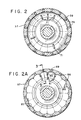
- Figure 2 and 2A are views taken along line 2-2 of Figure 1 showing alternative structures for handling mixed return flow and wash liquid in the separation chamber of a centrifuge;
- Figure 3 is a view of an alternative structure of a tube for injecting a mixed return flow and wash liquid into the separation chamber;
- Figure 4 is an enlarged view in section of an alternate impeller structure in accordance with the invention for introducing wash liquid with return flow into the centrifuge;
- Figure 4A is a perspective view of the impeller of Figure 4;
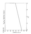
- Figure 5 is a graph showing the improved % displacement achieved using high-rate washing on a modified starch feed in accordance with the invention;
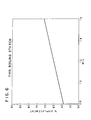
- Figure 6 is a graph similar to Figure 5 but showing improved % displacement achieved using a different modified starch feed; and
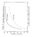
- Figure 7 is a further graph in which results obtained on various feeds over a much wider range of wash liquor/underflow liquor ratios are compiled.
- The structure of the
centrifuge 10 illustrated in Figure 1 of the drawing consists of a rotor 11 supported by avertical shaft 12, withinstationary housing 13. As will be presently described in more detail, the rotor is provided with various fluid passages, including an inlet for the fluid feed material, an outlet for discharge of the lighter centrifugally separable component of the feed material, known as the overflow, and an outlet for the heavier centrifugally separable component of the feed material, known as the underflow. The rotor 11 is supported and driven by the vertically disposedshaft 12, which is connected to a vertical coaxially aligned motor driven shaft (not shown). -
Housing 13 can be conveniently formed ofseparable sections Section 18 forms a volute orannular chamber 21 for receiving the centrifugally separated overflow discharge from the rotor 11, andsection 19 is formed to provide a volute orannular chamber 22 for receiving the underflow discharge from the rotor 11. - The body of rotor 11 is, likewise, preferably made of a number of separable annular parts including a
main part 23 and mating upper andlower parts Part 23 is secured to the lower part orinner structure 27 of the rotor which is attached to the lower end of therotor shaft 12.Parts clamping ring 29. Between theinner structure 27 and theinner surfaces rotor parts separating chamber 32. - A stack of axially spaced annular separating
discs 35, which are of conventional, truncated conical form, is mounted in thechamber 32 coaxial withshaft 12. A plurality of equiangularly spacedunderflow discharge nozzles 36, each of which is provided with a discharge orifice directed backwardly with respect to the direction of rotation of the rotor 11 (as seen in Fig. 2), are formed through the outerperipheral wall 37 of themain rotor part 23. - The peripheral portion of the
main rotor part 23 with thenozzles 36, extends within thethroat 38 of thevolute chamber 22 formed byhousing part 19. - In operation of the centrifuge the concentrate or underflow component is forced to that portion of
chamber 32 adjacent to thenozzles 36 for discharge therethrough into theunderflow receiving volute 22 ofhousing member 19. The underflow passes continuously fromunderflow volute 22 through apipe 40. - Fluid feed material is supplied to the rotor 11 through an
inlet pipe 42 which is connected to annularvertical channel 43 defined between the pair of coaxially alignedtubular members 44 and 45 concentric withdrive shaft 12.Channel 43 discharges downwardly into a receivingchamber 46 defined between truncatedconical member 47 and theinner rotor structure 27. The feed flows from receivingchamber 46 through passage 48 into separatingchamber 32. - From the truncated
conical member 47 there extend upwardly a number of fins 41 which support the stack ofdiscs 35 and also definepassages 51 which accommodate the upward flow of the overflow component of the centrifuge. It will be noted thatpassages 51 discharge the overflow withinhousing 13 toannular chamber 21. - In the
annular chamber 46 are located a number of fins orvanes 52 which rotate with theinner rotor structure 27 and consequently impart radially outward motion to the feed flow passing throughchamber 46. - The centrifuge of the invention is adapted for the return of a portion of the underflow. The lower part of
housing 19 and thelower portion 27 of the rotor 11 are provided withopenings central opening 64 is provided in opening 59 ofrotor portion 27 to encloseimpeller chamber 55; the latter defined by fitting 61 androtor portion 27. About opening 58 inhousing 19 is secured the upwardly and interiorly directednozzle element 67 which terminates within opening 64 in fitting 61. - Within
impeller chamber 55 there is ahub cap 69 and a plurality ofvanes 70. Upwardly and outwardly directedtubes 71, lying close towall 30 in separatingchamber 32, are connected topassages 72 which communicate withimpeller chamber 55 throughrotor portion 27. The upper ends of thetube 71 terminate quite near the entry tonozzles 36. - A
return conduit 63 is at one end connected to theunderflow conduit 40 and, at the other end, turns upward for connection to theopening 58 inhousing 19. Awash pipe 75 passes through a fitting 79 in thereturn conduit 63 and extends upward centrally of the return conduit to terminate withinnozzle element 67. - In operation, a slurry feed is introduced through
inlet pipe 42. The feed flows intoannular passage 43 and from there intochamber 46 where radially outward motion is imparted to the slurry byvanes 52. The feed slurry then passes into separatingchamber 32 through passages 48 and is there subjected to high centrifugal forces which drive the fraction having high specific gravity toward thenozzles 36 while the lighter fraction is moved to the separatingdiscs 35. Any relatively heavy components carried with the lighter fraction are deposited on thediscs 35 and the lightfraction passes upward alongpassages 51 between ribs 41 as overflow intoannular chamber 21. The deposit which accumulates ondiscs 35 drops off from time to time in separatingchamber 32 and centrifugal forces drive this material towardnozzles 36. The overflow fromchamber 21 is removed from the centrifuge for further treatment or disposal throughconduit 28. - The heavy fraction, after contact in the separating
chamber 32 with washed return flow, is ejected throughnozzles 36 into annularchamber22 as underflow and from there is routed toconduit 40 which branches intovalved conduit 62 and returnconduit 63. By adjusting valve 62' the flows throughconduit valved conduit 62 thus leaving the system. Returnconduit 63 is connected toconduit 40 and conducts a portion of the underflow to theimpeller chamber 55 of the centrifuge throughnozzle element 67. Washnozzle 75 injects a high volume of wash liquid throughnozzle element 67 into theimpeller chamber 55. With thewash nozzle 75 located centrally ofnozzle element 67, theannular space 81 betweennozzle 75 and the interior ofnozzle element 67 constitutes a venturi throat. Thus, when liquid is flowing throughnozzles annular space 81 and this increases the pressure differential between theannular chamber 22 and thenozzle element 67. The higher pressure differential assures increased flow inreturn line 63. - The combined return flow from
conduit 63 and the wash liquidenter impeller chamber 55 wherehub cap 69 directs the highly dilute flow into contact with impeller fins orvanes 70. Radially outward motion is imparted to the mixed liquid by thefins 70. The impeller forces the liquid throughpassages 72 into thetubes 71. The liquid is thus injected bytubes 71 into the separatingchamber 32 near the inlet side ofnozzles 36. In separatingchamber 32 the highly dilute flow fromtubes 71 meets the feed flow undergoing separation therein. The liquid associated with the high specific gravity component of the feed is displaced by the high volume of dilute liquid issuing from thetubes 71 and the displaced liquid, with its high solubles content, then moves via the separating discs to the overflow. - In Figure 2 in a section taken along line 2-2 of Figure 1, the
nozzles 36 are shown together with their relationship totubes 71. Clearly seen in this view is the bacward direction orrelief 39 provided the discharge orifice ofnozzle 36. Thetubes 71 discharge their high wash charge between and close toadjacent nozzles 36 and displace the high solubles liquid component of feed; the low solubles liquid leaving in the underflow while the high solubles liquid is discharged to overflow. - In Figures 2A and 3 there is shown an alternative structure of the
tube 71 and nozzle entry shown in Figures 1 and 2. In thiscase tube 81 extends upward betweennozzles 36 but quite close to the level of the nozzles and has ahood element 83 which extends to the nozzle level giving the tube a "cobra" configuration. In addition, the entry or portal portion of thenozzles 36 is in the form ofscallops 85 so that the heavy fraction has a settling region or volume at the entry to the nozzles for accumulating material for ejection through the nozzles. The hooded aspect of thetubes 81 tends to concentrate the dilute mixed return flow at the scalloped portals so that the liquid associated with the feed flow and burdened with its high solubles content is displaced to overflow. -
Static mixing elements 80 may be provided intubes 71 and 81 (as in Figure 3) to promote thorough mixing of wash liquid and return flow prior to injection into separatingchamber 32. - In Figures 4 and 4A is shown an
alternative impeller structure 90 intended for a centrifuge of greater capacity than that illustrated in Figure 1. Theimpeller chamber 99 includes animpeller structure 90 comprising ahub cap 91 in which are secured a plurality ofradial vanes 93 which have liftingsurfaces 95 provided at the lower inner portion thereof. At the outer extremity of thevanes 93 the lower edge portions thereof are fixed as by welding or otherwise in aring member 97 which is secured directly or indirectly to therotor member 98. Figure 4A shows this impeller structure in perspective and it will be understood that this impeller structure rotates with the rotor structure of the centrifuge and receives return flow from nozzle 67 (Figure 4) together with wash liquid fromnozzle 75. Thehub cap 91 guides this mixed flow into the spaces between therotating vanes 93 and the lifting surfaces 95 on the vanes drive the mixed flow upward toward the tubes leading into the separating chamber of the centrifuge. - Foam is very detrimental when handling fluid so provision must be made for reducing foam in the centrifuge by removing the gases which become associated with the feed, return flow and wash liquid of the process. In the case of the feed, the gas flows with the feed downward in
feed passage 43 past the end of annular tube 44 at which point the gas rises along a narrow annular vent passage (not shown) about the exterior wall of annular tube 44 and passes intovolute chamber 21.Chamber 21 oroverflow conduit 28 or both are provided with vents (not shown) to discharge the gas. The gas introduced with the return flow or wash liquid and agitated inimpeller chamber 55 is vented intohousing 19 throughpassage 66 about theconvergent nozzle 67.Housing 19 is provided with vent means (not shown) to discharge the gas. - It is crucial that the mixture of wash water and return flow be defoamed to preserve high flow rates and to avoid driving entrained foam into the thickening zone of the rotor.
- The effect of wash liquid/underflow draw-off (W/U) ratios above .5 on the % displacement of original liquid from the feed slurry is demonstrated in the graphs of Figures 5 and 6.
- In the case of the "% displacement" term in Figures 5, 6 and 7, this refers to the amount of solubles removed from the feed liquid by the washing process of the invention.
- Interpreting
Fgure 5 then, it is clear that a feed (starch modified by treatment with sodium sulfate) which was subjected to washing in accordance with the invention using a wash liquid/underflow draw-off ratio (W/U) of 0.9 emerged with almost 70% of original soluble content removed. Increasing the W/U ratio to 2.1 removed somewhat more than an additional 15% of the original soluble content reacting approximately an 85% displacement level. - In Figure 6, which is directed to tests carried out on starch which was modified by hydrochloric acid treatment to give it thin boiling properties, it is seen that over the range of 0.8 to 1.6 W/U the % displacement increases from less than 60% to about 75%.
- By further increasing the W/U ratio % displacement levels in excess of 90% are achievable as seen in Figure 7.
- Figure 7 shows curves developed from many tests using various feeds over a wide range of wash liquor/underflow liquor ratios. The two curves demonstrate the improvement in % impurity removed obtained by employing high-rate washing (displacement washing) as opposed to the dilution washing. It is seen that with displacement washing over 90% impurity removal is obtained at about a wash liquor/underflow liquor ratio of 3.
- In the high wash rate process of the invention there are great benefits in classification because the action of the inward flowing wash stream in the separation chamber of the centrifuge lifts the fines right out of the fluid bed. For example, with a mixture of starch and gluten of 10% protein in the feed, an overflow fraction of 70% protein and an underflow fraction of 6% can be obtained using no wash. Using a wash ratio of 2 W/U, an underflow fraction can be obtained containing no more than 1% protein (still with 70% protein in the overflow).
- Solids of the same type can also be classified by this high rate wash centrifuge process on the basis of size alone. Thus, the removal of kaolin particles of less than 0.25 microns from a mixture of kaolin clay particles ranging from 0.10 microns to 2.0 microns is effected using an upflow wash of 1.5 W/U in the centrifuge.
- The invention may be embodied in other specific forms and processes without departing from the spirit or essential characteristics thereof. The present embodiments are therefore to be considered in all respects as illustrative and not restrictive, the scope of the invention being indicated by the appended claims rather than by the foregoing description, and all changes which come within the meaning and range of equivalency of the claims are therefore intended to be embraced therein.
Claims (14)
Applications Claiming Priority (2)
| Application Number | Priority Date | Filing Date | Title |
|---|---|---|---|
| US61204490A | 1990-11-13 | 1990-11-13 | |
| US612044 | 1990-11-13 |
Publications (2)
| Publication Number | Publication Date |
|---|---|
| EP0486260A2 true EP0486260A2 (en) | 1992-05-20 |
| EP0486260A3 EP0486260A3 (en) | 1992-07-01 |
Family
ID=24451482
Family Applications (1)
| Application Number | Title | Priority Date | Filing Date |
|---|---|---|---|
| EP19910310427 Withdrawn EP0486260A3 (en) | 1990-11-13 | 1991-11-12 | High-rate washing centrifuge |
Country Status (19)
| Country | Link |
|---|---|
| EP (1) | EP0486260A3 (en) |
| JP (1) | JPH04284865A (en) |
| KR (1) | KR920009453A (en) |
| CN (1) | CN1061357A (en) |
| AU (1) | AU8015491A (en) |
| BR (1) | BR9104626A (en) |
| CA (1) | CA2044299A1 (en) |
| EG (1) | EG19480A (en) |
| FI (1) | FI915327A (en) |
| HU (1) | HUT61225A (en) |
| IE (1) | IE912540A1 (en) |
| IL (1) | IL98364A0 (en) |
| MA (1) | MA22309A1 (en) |
| MX (1) | MX9100748A (en) |
| NO (1) | NO914427L (en) |
| NZ (1) | NZ238772A (en) |
| PE (1) | PE29091A1 (en) |
| PT (1) | PT98723A (en) |
| ZA (1) | ZA914723B (en) |
Cited By (3)
| Publication number | Priority date | Publication date | Assignee | Title |
|---|---|---|---|---|
| US6475132B2 (en) | 2000-06-16 | 2002-11-05 | Westfalia Separator Food Tec Gmbh | Double-intake disk centrifuge |
| EP2566626B2 (en) † | 2010-05-03 | 2017-10-25 | GEA Mechanical Equipment GmbH | Nozzle separator and method for diverting a solid phase from the nozzle separator |
| WO2022263183A1 (en) * | 2021-06-17 | 2022-12-22 | Gea Westfalia Separator Group Gmbh | Centrifuge drum of a nozzle separator, and nozzle separator |
Families Citing this family (1)
| Publication number | Priority date | Publication date | Assignee | Title |
|---|---|---|---|---|
| CN100418603C (en) * | 2006-01-23 | 2008-09-17 | 吴庆元 | Spherical separating unit |
Citations (4)
| Publication number | Priority date | Publication date | Assignee | Title |
|---|---|---|---|---|
| US3073516A (en) * | 1959-08-06 | 1963-01-15 | Dorr Oliver Inc | Centrifuges |
| US3080108A (en) * | 1961-01-12 | 1963-03-05 | Dorr Oliver Inc | Centrifugal machines having a nozzle type rotor structure |
| FR1549797A (en) * | 1966-12-21 | 1968-12-13 | ||
| US3443746A (en) * | 1967-01-19 | 1969-05-13 | Dorr Oliver Inc | Counter-current wash for centrifugal separator |
-
1991
- 1991-06-04 IL IL98364A patent/IL98364A0/en unknown
- 1991-06-11 CA CA002044299A patent/CA2044299A1/en not_active Abandoned
- 1991-06-19 ZA ZA914723A patent/ZA914723B/en unknown
- 1991-06-20 HU HU912060A patent/HUT61225A/en unknown
- 1991-06-28 NZ NZ238772A patent/NZ238772A/en unknown
- 1991-07-02 AU AU80154/91A patent/AU8015491A/en not_active Abandoned
- 1991-07-03 MA MA22475A patent/MA22309A1/en unknown
- 1991-07-15 EG EG43091A patent/EG19480A/en active
- 1991-07-18 KR KR1019910012244A patent/KR920009453A/en not_active Application Discontinuation
- 1991-07-19 IE IE254091A patent/IE912540A1/en unknown
- 1991-07-30 PE PE1991188926A patent/PE29091A1/en unknown
- 1991-08-20 MX MX9100748A patent/MX9100748A/en unknown
- 1991-08-20 PT PT98723A patent/PT98723A/en not_active Application Discontinuation
- 1991-10-01 JP JP3280742A patent/JPH04284865A/en active Pending
- 1991-10-25 BR BR919104626A patent/BR9104626A/en not_active Application Discontinuation
- 1991-11-09 CN CN91110539A patent/CN1061357A/en active Pending
- 1991-11-12 NO NO91914427A patent/NO914427L/en unknown
- 1991-11-12 FI FI915327A patent/FI915327A/en not_active Application Discontinuation
- 1991-11-12 EP EP19910310427 patent/EP0486260A3/en not_active Withdrawn
Patent Citations (4)
| Publication number | Priority date | Publication date | Assignee | Title |
|---|---|---|---|---|
| US3073516A (en) * | 1959-08-06 | 1963-01-15 | Dorr Oliver Inc | Centrifuges |
| US3080108A (en) * | 1961-01-12 | 1963-03-05 | Dorr Oliver Inc | Centrifugal machines having a nozzle type rotor structure |
| FR1549797A (en) * | 1966-12-21 | 1968-12-13 | ||
| US3443746A (en) * | 1967-01-19 | 1969-05-13 | Dorr Oliver Inc | Counter-current wash for centrifugal separator |
Cited By (3)
| Publication number | Priority date | Publication date | Assignee | Title |
|---|---|---|---|---|
| US6475132B2 (en) | 2000-06-16 | 2002-11-05 | Westfalia Separator Food Tec Gmbh | Double-intake disk centrifuge |
| EP2566626B2 (en) † | 2010-05-03 | 2017-10-25 | GEA Mechanical Equipment GmbH | Nozzle separator and method for diverting a solid phase from the nozzle separator |
| WO2022263183A1 (en) * | 2021-06-17 | 2022-12-22 | Gea Westfalia Separator Group Gmbh | Centrifuge drum of a nozzle separator, and nozzle separator |
Also Published As
| Publication number | Publication date |
|---|---|
| ZA914723B (en) | 1993-02-24 |
| CA2044299A1 (en) | 1992-05-14 |
| IE912540A1 (en) | 1992-05-20 |
| NZ238772A (en) | 1993-09-27 |
| JPH04284865A (en) | 1992-10-09 |
| NO914427D0 (en) | 1991-11-12 |
| EP0486260A3 (en) | 1992-07-01 |
| HUT61225A (en) | 1992-12-28 |
| MA22309A1 (en) | 1992-07-01 |
| AU8015491A (en) | 1992-05-14 |
| MX9100748A (en) | 1992-07-08 |
| PE29091A1 (en) | 1991-10-07 |
| NO914427L (en) | 1992-05-14 |
| BR9104626A (en) | 1992-06-23 |
| PT98723A (en) | 1993-09-30 |
| FI915327A (en) | 1992-05-14 |
| KR920009453A (en) | 1992-06-25 |
| EG19480A (en) | 1995-04-30 |
| FI915327A0 (en) | 1991-11-12 |
| CN1061357A (en) | 1992-05-27 |
| HU912060D0 (en) | 1991-12-30 |
| IL98364A0 (en) | 1992-07-15 |
Similar Documents
| Publication | Publication Date | Title |
|---|---|---|
| US5370600A (en) | Apparatus for separating lighter and heavier components of a mixture employing a removable liner | |
| US4216095A (en) | Dynamic dense media separator | |
| US5300222A (en) | Water clarification method and apparatus | |
| US4470902A (en) | Method and apparatus for classifying particles | |
| JP3848372B2 (en) | Apparatus and method for discontinuously separating solid particles from a liquid | |
| US4711720A (en) | Tangentially staged hydrocyclones | |
| US4451247A (en) | Continuous, completely jacketed, countercurrent centrifugal extractor | |
| US4362536A (en) | Pulp degassing | |
| US4252640A (en) | Apparatus for sorting fibrous stock suspensions | |
| JPH01270913A (en) | Sedimentation tank used for separating activated sludge from waste water suspension containing activated sludge | |
| EP0486260A2 (en) | High-rate washing centrifuge | |
| US11207614B2 (en) | Single stage clarifier and mixing assembly | |
| CN107051752A (en) | Flotation device | |
| US2958461A (en) | Centrifuge machine | |
| US5823937A (en) | Low-shear feeding system for use with centrifuges | |
| US4806019A (en) | Method and apparatus for mixing two or more components such as immiscible liquids | |
| WO1997016256A9 (en) | Low-shear centrifuge feeding system | |
| JPS60501197A (en) | Turbine type centrifugal separator for suspension separation | |
| EP0606716B1 (en) | Method and apparatus for separating phases | |
| CN211707102U (en) | Centrifugal continuous concentrating machine | |
| WO2013173852A1 (en) | Separator and method for treatment of a contaminated liquid | |
| WO1982002344A1 (en) | Fluid recovery system | |
| US4365741A (en) | Continuous centrifugal separation of coal from sulfur compounds and mineral impurities | |
| US3406825A (en) | Centripetal separation method and apparatus | |
| US2551820A (en) | Extraction column |
Legal Events
| Date | Code | Title | Description |
|---|---|---|---|
| PUAI | Public reference made under article 153(3) epc to a published international application that has entered the european phase |
Free format text: ORIGINAL CODE: 0009012 |
|
| PUAL | Search report despatched |
Free format text: ORIGINAL CODE: 0009013 |
|
| AK | Designated contracting states |
Kind code of ref document: A2 Designated state(s): AT BE CH DE DK ES FR GB GR IT LI LU NL SE |
|
| AK | Designated contracting states |
Kind code of ref document: A3 Designated state(s): AT BE CH DE DK ES FR GB GR IT LI LU NL SE |
|
| 17P | Request for examination filed |
Effective date: 19921218 |
|
| 17Q | First examination report despatched |
Effective date: 19931202 |
|
| STAA | Information on the status of an ep patent application or granted ep patent |
Free format text: STATUS: THE APPLICATION IS DEEMED TO BE WITHDRAWN |
|
| 18D | Application deemed to be withdrawn |
Effective date: 19951003 |