EP0486081B1 - Fahrzeugscheibenantenne - Google Patents
Fahrzeugscheibenantenne Download PDFInfo
- Publication number
- EP0486081B1 EP0486081B1 EP91202779A EP91202779A EP0486081B1 EP 0486081 B1 EP0486081 B1 EP 0486081B1 EP 91202779 A EP91202779 A EP 91202779A EP 91202779 A EP91202779 A EP 91202779A EP 0486081 B1 EP0486081 B1 EP 0486081B1
- Authority
- EP
- European Patent Office
- Prior art keywords
- window
- antenna
- principal element
- edge
- vehicle
- Prior art date
- Legal status (The legal status is an assumption and is not a legal conclusion. Google has not performed a legal analysis and makes no representation as to the accuracy of the status listed.)
- Expired - Lifetime
Links
Images
Classifications
-
- H—ELECTRICITY
- H01—ELECTRIC ELEMENTS
- H01Q—ANTENNAS, i.e. RADIO AERIALS
- H01Q1/00—Details of, or arrangements associated with, antennas
- H01Q1/12—Supports; Mounting means
- H01Q1/1271—Supports; Mounting means for mounting on windscreens
Definitions
- This invention relates to a window assembly for a vehicle, which includes an antenna formed of a substantially rectangular and transparent film of electrically conductive material.
- the traditional mast or whip antenna has been used for several years to receive and transmit radio waves from a motor vehicle.
- these antennas have provided satisfactory performance, but they tend to distract from the aesthetic appearance of the vehicle, and several attempts have been made in the past to develop more inconspicuous antennas that can be integrated directly into the structure of the vehicle.
- solid wires or opaque thick strips of conductive materials have been disposed on or within the window glass of vehicles to provide antennas for replacing conventional whip antennas.
- the antennas resulting from such efforts have unsuitably obstructed the view of the vehicle occupants, or have performed unsatisfactorily as compared to the traditional whip or mast-type antenna.
- FR-A-2601194 discloses a vehicle window which incorporates an antenna in the form of a transparent film having a trapezoidal shape equivalent to the shape of the window and which covers most of the surface of the window but is spaced from each window edge by a predetermined distance.
- a line or conductive wire is coupled to a supply point of the antenna proximate the centre of the window.
- JP-A-62/49703 discloses an antenna element formed from a coloured heat ray reflective transparent conductive film which has a light intercepting property and can be used as the upper side section of a glass plate of an automatic window.
- the present invention seeks to provide an improved vehicle window and antenna assembly.
- an aspect of the present invention provides a window assembly for a vehicle as specified in claim 1.
- the invention can provide a thin film antenna which does not have to occupy a major central region of a vehicle window so that an acceptable antenna gain can be achieved by increasing the film conductivity without making the antenna unsightly or unsuitably conspicuous to vehicle occupants.
- the central region of a vehicle window is not considered sufficiently transparent when its transmittance is less than 70% for visible light.
- Commercially available conducting films typically require a direct current surface resistivity in the order or 4 to 8 ohms per square to achieve 70% transmittance.
- the gain of antennas fabricated from such films can be diminished by as much as 3 dB, due to the ohmic loss in the films.
- the present invention recognizes and takes advantage of electromagnetic coupling existing between an antenna and the metallic structure of a vehicle. By effectively utilizing this coupling, it has been found that a thin film antenna can be restricted to the upper region of a vehicle window, and still provide acceptable antenna'performance. Since such an antenna does not occupy a major central portion of the window, less transparent films may be used to reduce ohmic loss and improve antenna gain.
- a transparent conductive film antenna for the upper portion of window glass, which is disposed within an aperture formed in the metallic structure of a vehicle.
- the antenna includes a principal element formed of a thin transparent film of electrically conductive material, in the general shape of a horizontally elongate rectangle, which is supported on or within the vehicle window glass.
- the upper and lower edges of the principal element are separated by a width W, with the upper edge spaced a distance D from the top edge of the window glass.
- the dimensions W and D are selected such that their sum does not exceed one-third of the distance separating the top and bottom edges of the window, thereby confining the principal element to the upper region of the window glass.
- the principal element is electrically fed with respect a ground point on the vehicle to electromagnetically couple the principal element to the vehicle metallic structure.
- the transparent film antenna can be restricted to the upper region of the vehicle window, and still provide adequate performance.
- less transparent, but more conductive films may be used in fabricating the antenna.
- ohmic loss can be reduced to improve antenna gain, without unsuitably obstructing the view of vehicle occupants.
- the principal element of the antenna is symmetrically positioned about the vertical centre line of the window, with a feed point located at the centre of its upper edge.
- a feed point located at the centre of its upper edge.
- the upper region of the vehicle window includes a tinted band and the rectangular shaped principal element is surrounded by the tinted band, making the antenna less noticeable to vehicle occupants.
- means for tuning the antenna can be provided by an optional auxiliary element.
- the auxiliary element is preferably formed from the same transparent conductive film as the principal element, and has the general shape of a vertically elongated rectangle.
- the auxiliary element may have its upper end electrically connected to the centre of the lower edge of the principal element, and extends in a downwardly direction to give the antenna a T-shaped configuration. The length of this auxiliary element will influence the antenna impedance and can be specified to provide a degree of tuning.
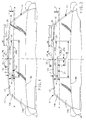
- FIG. 1 there is shown a portion of the metallic structure 10 of a vehicle, which forms an aperture 12 having window glass 14 disposed therein.
- Window glass 14 has a substantially horizontal top edge 14a and bottom edge 14b interfacing with the metallic structure 10 of the vehicle.
- a vertical axis V-V forms a centre line along aperture 12, which can be thought of as dividing window glass 14 symmetrically into equal right and left regions.
- a horizontal axis H-H along aperture 12, perpendicularly intersects the V-V axis to partition window glass 14 into an upper region 14c and a lower region 14d.
- the upper region 14c of window 14 is chosen to have a transverse width (along the V-V axis) of one-third of the distance separating top edge 14a and bottom edge 14b of window 14.
- window 14 is a standard laminated automobile windshield formed of two layers of glass with an interposing thermoplastic or polyvinyl butyral layer.
- Window 14 may optionally be provided with a longitudinally extending tinted band 16 across the top thereof, having a depth T in the transverse direction along the V-V axis. As will later be described, this tinted band may be utilized advantageously to conceal further the film antenna described below.
- a window antenna representing one embodiment of the present invention, generally designated as 18, is shown supported by and disposed in the upper region 14c of window 14, above the H-H axis.
- the antenna 18 includes a principal element 20 formed of a thin transparent film of electrically conducting material having a substantially rectangular elongate shape and disposed substantially horizontally across the vehicle windscreen 14.
- the principal element 20 is particularized by its horizontal length L, and transverse width W between its upper edge 20a and lower edge 20b, with the upper edge 20a being spaced a distance D from the top edge 14a of window glass 14.
- the transparent conductive film used in forming principal element 20 may be a single-layer film, for example, a single layer of indium-tin-oxide or a conducting metal such as copper or silver; or alternatively, it may be a multi-layer film having heat-reflecting ability, such as provided by layers of silver and titanium dioxide.
- any thin film of material having suitable transparency and conductivity, as described hereinafter, may be employed in forming antenna 18.
- a film of a conductive material such as copper or silver can be deposited directly on the surface of window glass 14 by sputtering or other physical or chemical vapor deposition techniques.
- the conductive film can be deposited onto a polyester sheet, which is then sandwiched between glass laminates during the window fabrication process.
- the film is formed in a continuous pattern, however, it may be advantageous to deposit the conductive material in a mesh-like pattern, thereby increasing the transparency of the film through the mesh openings.
- a coaxial cable 24, as shown schematically in Figure 1, is used to connect electrically a radio wave receiver/transmitter 26 to the principal element 20 of the antenna 18 and the metallic structure 10 of the vehicle.
- Inner conductor 28 of cable 24 is connected to a feed point 22 at the upper edge 20a of principal element 20, while the outer conductor or shield 30 is attached to a ground point 32 on the metallic vehicle structure 10.
- Ground point 32 is generally located directly adjacent to feed point 22, and as close as practicable to the top edge 14a of window glass 14.
- a thin filament of the same transparent conducting film used to form principal element 20 could be extended upward from feed point 22 to the top edge 14a of window glass 14.
- Inner conductor 28 could then be electrically attached to the filament at the edge of the window rather than at feed point 22.
- the electrical connection between conductor 28 and the thin conducting film of principal element 20 can be established by using commercially available conductive adhesives or mechanical fasteners. Many other standard approaches for effectuating a good electrical connection between a thin film and a conductor are generally known and will not be further discussed in the specification.
- the principal element 20 In electrically feeding the principal element 20 with respect to ground point 32, as described above, the principal element 20 is electromagnetically coupled to the vehicle metallic structure 10, primarily across the top edge 14a of window glass 14. It has been recognized that by adjusting this coupling, the performance of antenna 18 may be enhanced to approach that of a vehicle mounted whip or mast type antenna.
- the coupling between the principal element 20 and the surrounding metallic vehicle structure 10 is not readily analyzable in a mathematical sense.
- the nature and degree of this electrical coupling, and its effect on antenna performance will depend upon the position of feed point 22 on the upper edge 20a of principal element 20; the physical size and location of principal element 20 on the window glass 14; the shape of aperture 12 and the metallic structure 10 of the vehicle; the dielectric properties of the window glass 14; and the frequency range (band) of the radio waves to be received/transmitted by antenna 18.
- the optimal feed point location, length L, width W, and position of principal element 20 on the window glass 14 may be determined experimentally by measuring antenna gain and the impedance developed between feed point 22 and ground point 32, while varying these parameters of antenna 18. It has been found that this can be conveniently accomplished by initially forming principal element 20 from a commercially available, highly conductive, aluminium tape. The tape can be easily moved on the window and/or reduced in size to obtain the approximate dimensions and spacing for antenna 18, prior to forming it from the actual conducting film material. It has been found that the primary effect resulting from the substitution of a relative low loss film for the aluminium tape is a slight decrease in average antenna gain, due to the ohmic loss in the film.
- the length L of the principal element is selected to achieve a zero reactive impedance component for the antenna 18 at a resonant frequency f o , which is customarily near the mean frequency for a band of radio waves to be received/transmitted by antenna 18.
- the measured resonant length L has been less than ⁇ o /4, where ⁇ o is the free space wavelength associated with the chosen resonant frequency f o .
- the width W and spacing D of principal element 20 are selected to maximize antenna gain for the particular application, while restricting the lower edge 20b of principal element 20 to the upper region 14c of window 14. This last requirement is satisfied if the sum of dimensions W and D does not exceed one-third of the transverse width of window glass 14 along its centre line (axis V-V).
- a film antenna was produced for the FM broadcast band (88 - 108 MHz) on the basis of the above-described principles.
- the principal element 20 was formed from a thin film of copper having a direct current surface resistivity of approximately 2 ohms per square.
- a standard 50 ohm RG 58 coaxial cable was used as the cable 24 to feed antenna 18.
- a transmittance of less than 70% for principal element 20 should be acceptable to vehicle occupants, since principal element 20 has been restricted to the upper region of window 14, out of the central viewing area.
- thin films having relatively low surface resistivities can be used in forming antenna 18, thereby reducing ohmic loss and increasing antenna gain.
- the vertical and horizontal polarized FM gains of the above described film antenna and a conventional rear mounted whip on the sample vehicle were measured at three frequencies, 88.2, 98.4, and 108.2 MHz.
- the gain of film antenna 18 was found to be 2.4 dB below that of the rear mounted whip, indicating that it is an acceptable replacement for the whip in the FM band.
- film antenna 18 was found to have an average voltage standing wave ratio (VSWR) of 1.7 in the FM band, with respect to a 50 ohm reference, indicating a good antenna impedance match with the 50 ohm RG 58 coaxial cable 24.
- VSWR average voltage standing wave ratio
- the average gain of film antenna 18 was also measured for the AM broadcast band (560 - 1600 KHz), and found to be approximately 10.9 dB below that of the rear mounted whip antenna. However, it was found that the AM gain could be increased by 8.2 dB, to an acceptable level, if 125 ohm RG 62 A/U modified coaxial cable was used in place of the RG 58 coaxial cable 30 to feed antenna 18.
- the RG 62 A/U cable has roughly one-third the distributed capacitance of the RG 58 cable, so less AM signal is shunted to ground, thereby effectively increasing the AM gain for receiver/transmitter 26. This substitution of cable does, however, result in approximately 2.2 dB decrease in the average FM gain of antenna 18, since it was more nearly impedance matched to the 50 ohm RG 58 cable.
- Film antenna 36 comprises the principal element 20, as previously described, and further includes an auxiliary element 36, which can be used to tune the antenna impedance developed between feed point 22 and ground point 32.
- auxiliary element is formed of thin transparent conducting film in the general shape of a vertically elongated rectangle having a length L' and width W'.
- An end 36a of auxiliary element 36 is electrically connected to principal element 20 near the centre of its lower edge 20b, giving antenna 34 a T-shaped configuration.
- the auxiliary element 36 behaves as a short inverted vertical monopole, with respect to the metallic structure 10, with an associated impedance which varies primarily as a function of its length L'.
- auxiliary element 36 By attaching auxiliary element 36 to principal element 20, their respective impedances essentially combine in parallel and appear as the total impedance for antenna 34 between feed point 22 and ground point 32.
- the impedance of antenna 34 can be tuned by adjusting the length L' of auxiliary element 36. This can be particularly useful in improving the impedance match between a particular coaxial cable 24 and film antenna 34 to maximize antenna gain.
- the presence of the auxiliary tuning element 36, down the centre line of the window must be acceptable in the particular application.
- auxiliary element 36 may be used to form both principal element 20 and auxiliary element 36, in which case, top edge 36a of auxiliary element 36 would not physically exist, since both of these portions of antenna 34 would normally be fabricated at the same time.
- different conducting films could be used when forming the principal element 20, and auxiliary element 36. This might be desirable, for example, to increase the transparency of the auxiliary element, which can pass through the centre region of window 14 along the centre line.
- auxiliary element 36 could also take the form of a thin wire, fashioned from an electrically conducting metal such as copper, which would be even less noticeable to vehicle occupants.
- a film antenna 34 was fabricated and attached to the window 14 of a second sample vehicle.
- the principal element 20 and auxiliary element 36 were both formed from a copper film having a surface resistivity of 2 ohms per square.
- L' 0.508 m.
- the average FM gain of film antenna 34 was found to be 0.6 dB below that of a rear mounted whip antenna, while the average AM gain was 1.3 dB above that of the whip antenna.
- antenna 34 represents an acceptable replacement for a rear mounted whip antenna.
- the transparent film antennas described can provide satisfactory performance without being unsuitably conspicuous to vehicle occupants.
- the preferred embodiments have been described in terms of antennas for AM/FM reception, it will be understood by those skilled in the art that they could be adapted for use at other frequencies such as in the commercial TV or mobile telephone bands.
Claims (7)
- Eine Fensteranordnung für ein Fahrzeug mit einem Fenster mit einer ersten Kante (14a), die im Gebrauch eine obere Kante des Fensters bildet; einer zweiten Kante (14b), die im Gebrauch eine untere Kante des Fensters bildet; einer Antenne (18) mit einem Hauptelement (20), das aus einem im wesentlichen transparenten Film aus elektrisch leitfähigem Material ausgebildet ist, welches durch das Fenster im wesentlichen parallel zu der ersten Kante getragen ist;
dadurch gekennzeichnet,
daß das Hauptelement im wesentlichen rechteckig und von der ersten Kante beabstandet ist, so daß die Summe aus der Breite (W) des Hauptelementes und des Abstandes (D) des Hauptelementes von der ersten Kante des Fensters ein Drittel der Entfernung, die die ersten und zweiten Kanten des Fensters trennt, nicht übersteigt; und daß Speisemittel (22, 24), angepaßt sind, um das Hauptelement an die Metallstruktur eines Fahrzeuges elektromagnetisch zu koppeln. - Eine Fensteranordnung nach Anspruch 1, worin das Hauptelement 20 der Antenne eine Länge (L) aufweist, die kleiner ist als ein Viertel der freien Raumwellenlänge (λ₀) einer ausgewählten Resonanzfrequenz für die Antenne.
- Eine Fensteranordnung nach Anspruch 1 oder 2 mit Abstimmungsmitteln (36) die angepaßt sind, um die Impedanz der Antenne abzustimmen.
- Eine Fensteranordnung nach Anspruch 3, worin das Abstimungsmittel ein Zusatzelement (36) umfaßt, welches einen im wesentlichen transparenten und im wesentlichen rechteckigen leitfähigen Film umfaßt, der sich von dem Hauptelement auf die zweite Kante des Fensters zu erstreckt, wobei das Zusatzelement eine vorbestimmte Länge aufweist die angepaßt ist, um die Impedanz der Antenne zu beeinflussen.
- Eine Fensteranordnung nach einem der vorhergehenden Ansprüche, worin das Hauptelement (20) und/oder das Zusatzelement (36) eine Lichttransmittanz von weniger als 70 % aufweisen.
- Eine Fensteranordnung nach einem der vorhergehenden Ansprüche, worin das Hauptelement (20) im wesentlichen zentral relativ zu der ersten Kante positioniert ist, und das Speisemittel (22, 24) einen Speisepunkt (22) umfaßt, der im wesentlichen an der Mitte einer Kante des Hauptelementes benachbart zu der ersten Kante des Fensters angeordnet ist.
- Eine Fensteranordnung nach einem der vorhergehenden Ansprüche, worin das Fenster ein getöntes Band (16) umfaßt, innerhalb dessen das Hauptelement angeordnet ist.
Applications Claiming Priority (2)
| Application Number | Priority Date | Filing Date | Title |
|---|---|---|---|
| US07/612,295 US5083135A (en) | 1990-11-13 | 1990-11-13 | Transparent film antenna for a vehicle window |
| US612295 | 1990-11-13 |
Publications (3)
| Publication Number | Publication Date |
|---|---|
| EP0486081A2 EP0486081A2 (de) | 1992-05-20 |
| EP0486081A3 EP0486081A3 (en) | 1992-07-15 |
| EP0486081B1 true EP0486081B1 (de) | 1995-08-16 |
Family
ID=24452564
Family Applications (1)
| Application Number | Title | Priority Date | Filing Date |
|---|---|---|---|
| EP91202779A Expired - Lifetime EP0486081B1 (de) | 1990-11-13 | 1991-10-25 | Fahrzeugscheibenantenne |
Country Status (3)
| Country | Link |
|---|---|
| US (1) | US5083135A (de) |
| EP (1) | EP0486081B1 (de) |
| DE (1) | DE69112174T2 (de) |
Families Citing this family (105)
| Publication number | Priority date | Publication date | Assignee | Title |
|---|---|---|---|---|
| US5264858A (en) * | 1990-07-31 | 1993-11-23 | Asahi Glass Company Ltd. | Glass antenna for a telephone of an automobile |
| US5714959A (en) * | 1994-06-09 | 1998-02-03 | Delco Electronics Corporation | Glass patch cellular antenna |
| US5492750A (en) * | 1994-09-26 | 1996-02-20 | Ppg Industries, Inc. | Mask for coated glass |
| US5610618A (en) * | 1994-12-20 | 1997-03-11 | Ford Motor Company | Motor vehicle antenna systems |
| US5596335A (en) * | 1994-12-27 | 1997-01-21 | Ppg Industries, Inc. | Electrical connector |
| US5670966A (en) | 1994-12-27 | 1997-09-23 | Ppg Industries, Inc. | Glass antenna for vehicle window |
| US5640167A (en) * | 1995-01-27 | 1997-06-17 | Ford Motor Company | Vehicle window glass antenna arrangement |
| US5699054A (en) * | 1995-05-19 | 1997-12-16 | Prince Corporation | Trainable transceiver including a dynamically tunable antenna |
| US5686903A (en) * | 1995-05-19 | 1997-11-11 | Prince Corporation | Trainable RF transceiver |
| US5739794A (en) * | 1995-05-22 | 1998-04-14 | General Motors Corporation | Vehicle window antenna with parasitic slot transmission line |
| US5528314A (en) * | 1995-05-22 | 1996-06-18 | General Motors Corporation | Transparent vehicle window antenna |
| US5648785A (en) * | 1995-05-22 | 1997-07-15 | General Motors Corporation | Vehicle window with antenna connection apparatus |
| JP3741315B2 (ja) * | 1995-08-28 | 2006-02-01 | マツダ株式会社 | ガラスアンテナ及びアンテナ |
| US5748155A (en) * | 1995-09-13 | 1998-05-05 | Ppg Industries, Inc. | On-glass antenna and connector arrangement |
| US5712645A (en) * | 1995-10-06 | 1998-01-27 | Minnesota Mining And Manufacturing Company | Antenna adapted for placement in the window of a vehicle |
| US6043782A (en) * | 1995-12-18 | 2000-03-28 | Ppg Industries Ohio, Inc. | Antenna connector arrangement |
| SE9600321D0 (sv) * | 1996-01-30 | 1996-01-30 | Bjoern Heed | Antenn |
| JPH09298413A (ja) * | 1996-05-08 | 1997-11-18 | Harada Ind Co Ltd | 車載窓ガラスアンテナ装置 |
| DE19735395A1 (de) * | 1996-08-16 | 1998-02-19 | Lindenmeier Heinz | Fensterscheibenantenne mit einer transparenten leitfähigen Schicht |
| US5902536A (en) * | 1996-09-13 | 1999-05-11 | Ppg Industries Ohio Inc. | Method for sealing an electrical connection to a laminated transparency |
| US5999134A (en) * | 1996-12-19 | 1999-12-07 | Ppg Industries Ohio, Inc. | Glass antenna system with an impedance matching network |
| US5959581A (en) * | 1997-08-28 | 1999-09-28 | General Motors Corporation | Vehicle antenna system |
| US5872542A (en) * | 1998-02-13 | 1999-02-16 | Federal Data Corporation | Optically transparent microstrip patch and slot antennas |
| US6384790B2 (en) | 1998-06-15 | 2002-05-07 | Ppg Industries Ohio, Inc. | Antenna on-glass |
| US5999136A (en) * | 1998-08-07 | 1999-12-07 | Ppg Industries Ohio, Inc. | Use of electrically conductive ceramic paints in antenna systems |
| US6280821B1 (en) | 1998-09-10 | 2001-08-28 | Ppg Industries Ohio, Inc. | Reusable mask and method for coating substrate |
| US6031500A (en) * | 1999-04-01 | 2000-02-29 | General Motors Corporation | Broadband FM vehicle rear window antenna not requiring a boost amplifier |
| DE19925127C1 (de) * | 1999-06-02 | 2000-11-02 | Daimler Chrysler Ag | Antennenanordnung in Kraftfahrzeugen |
| US6211831B1 (en) * | 1999-06-24 | 2001-04-03 | Delphi Technologies, Inc. | Capacitive grounding system for VHF and UHF antennas |
| US6266023B1 (en) | 1999-06-24 | 2001-07-24 | Delphi Technologies, Inc. | Automotive radio frequency antenna system |
| DE10002777C1 (de) * | 2000-01-22 | 2001-08-09 | Saint Gobain Sekurit D Gmbh | Kontaktierung einer Scheibe mit elektrischen Funktionen |
| MXPA02007453A (es) | 2000-02-11 | 2002-12-13 | Ppg Ind Ohio Inc | Antena de vehiculo. |
| KR100428139B1 (ko) * | 2001-08-28 | 2004-04-30 | 현대자동차주식회사 | 차량용 글라스 안테나 |
| US6814795B2 (en) | 2001-11-27 | 2004-11-09 | Ferro Corporation | Hot melt conductor paste composition |
| US7388549B2 (en) * | 2004-07-28 | 2008-06-17 | Kuo Ching Chiang | Multi-band antenna |
| US20100026590A1 (en) * | 2004-07-28 | 2010-02-04 | Kuo-Ching Chiang | Thin film multi-band antenna |
| JP2010504032A (ja) | 2006-09-15 | 2010-02-04 | タレス アビオニクス インコーポレイテッド | 航空機との間でコンテンツを無線で転送するシステム及び方法 |
| US10681568B1 (en) | 2010-05-28 | 2020-06-09 | Cohere Technologies, Inc. | Methods of data channel characterization and uses thereof |
| US9444514B2 (en) | 2010-05-28 | 2016-09-13 | Cohere Technologies, Inc. | OTFS methods of data channel characterization and uses thereof |
| US9130638B2 (en) | 2011-05-26 | 2015-09-08 | Cohere Technologies, Inc. | Modulation and equalization in an orthonormal time-frequency shifting communications system |
| US9071286B2 (en) | 2011-05-26 | 2015-06-30 | Cohere Technologies, Inc. | Modulation and equalization in an orthonormal time-frequency shifting communications system |
| US10667148B1 (en) | 2010-05-28 | 2020-05-26 | Cohere Technologies, Inc. | Methods of operating and implementing wireless communications systems |
| US9071285B2 (en) | 2011-05-26 | 2015-06-30 | Cohere Technologies, Inc. | Modulation and equalization in an orthonormal time-frequency shifting communications system |
| US11943089B2 (en) | 2010-05-28 | 2024-03-26 | Cohere Technologies, Inc. | Modulation and equalization in an orthonormal time-shifting communications system |
| US8976851B2 (en) | 2011-05-26 | 2015-03-10 | Cohere Technologies, Inc. | Modulation and equalization in an orthonormal time-frequency shifting communications system |
| US8466842B2 (en) | 2010-10-22 | 2013-06-18 | Pittsburgh Glass Works, Llc | Window antenna |
| US8576130B2 (en) | 2010-10-22 | 2013-11-05 | Pittsburgh Glass Works, Llc | Wideband antenna |
| US9031141B2 (en) | 2011-05-26 | 2015-05-12 | Cohere Technologies, Inc. | Modulation and equalization in an orthonormal time-frequency shifting communications system |
| US10003487B2 (en) | 2013-03-15 | 2018-06-19 | Cohere Technologies, Inc. | Symplectic orthogonal time frequency space modulation system |
| US9912507B2 (en) | 2012-06-25 | 2018-03-06 | Cohere Technologies, Inc. | Orthogonal time frequency space communication system compatible with OFDM |
| US10411843B2 (en) | 2012-06-25 | 2019-09-10 | Cohere Technologies, Inc. | Orthogonal time frequency space communication system compatible with OFDM |
| US9967758B2 (en) | 2012-06-25 | 2018-05-08 | Cohere Technologies, Inc. | Multiple access in an orthogonal time frequency space communication system |
| US10090972B2 (en) | 2012-06-25 | 2018-10-02 | Cohere Technologies, Inc. | System and method for two-dimensional equalization in an orthogonal time frequency space communication system |
| US10469215B2 (en) | 2012-06-25 | 2019-11-05 | Cohere Technologies, Inc. | Orthogonal time frequency space modulation system for the Internet of Things |
| US9929783B2 (en) | 2012-06-25 | 2018-03-27 | Cohere Technologies, Inc. | Orthogonal time frequency space modulation system |
| US9337525B2 (en) | 2014-02-03 | 2016-05-10 | Pittsburgh Glass Works, Llc | Hidden window antenna |
| EP3295572A4 (de) | 2015-05-11 | 2018-12-26 | Cohere Technologies, Inc. | Systeme und verfahren für symplektische orthogonale zeitfrequenzverschiebungsmodulation und übertragung von daten |
| US10090973B2 (en) | 2015-05-11 | 2018-10-02 | Cohere Technologies, Inc. | Multiple access in an orthogonal time frequency space communication system |
| US9866363B2 (en) | 2015-06-18 | 2018-01-09 | Cohere Technologies, Inc. | System and method for coordinated management of network access points |
| US10574317B2 (en) | 2015-06-18 | 2020-02-25 | Cohere Technologies, Inc. | System and method for providing wireless communication services using configurable broadband infrastructure shared among multiple network operators |
| EP3314836B1 (de) | 2015-06-27 | 2022-10-26 | Cohere Technologies, Inc. | Ofdm-kompatibles orthogonales zeitfrequenzraumkommunikationssystem |
| US10892547B2 (en) | 2015-07-07 | 2021-01-12 | Cohere Technologies, Inc. | Inconspicuous multi-directional antenna system configured for multiple polarization modes |
| KR102616669B1 (ko) | 2015-07-12 | 2023-12-21 | 코히어 테크놀로지스, 아이엔씨. | 복수의 협대역 부-반송파 상에서의 직교 시간 주파수 공간 변조 |
| EP3348015B1 (de) | 2015-09-07 | 2022-09-07 | Cohere Technologies, Inc. | Mehrfachzugriff mittels orthogonaler zeitfrequenz-raummodulation |
| EP3378187B1 (de) | 2015-11-18 | 2022-03-30 | Cohere Technologies, Inc. | Verfahren für orthogonale zeitfrequenzraummodulation |
| EP3387748B1 (de) | 2015-12-09 | 2022-03-09 | Cohere Technologies, Inc. | Pilotverpackung mit komplexen orthogonalen funktionen |
| CN109348739B (zh) | 2016-02-25 | 2022-10-28 | 凝聚技术公司 | 用于无线通信的参考信号封装 |
| US10693692B2 (en) | 2016-03-23 | 2020-06-23 | Cohere Technologies, Inc. | Receiver-side processing of orthogonal time frequency space modulated signals |
| CN109845102B (zh) | 2016-03-31 | 2023-07-28 | 凝聚技术公司 | 使用正交时间频率空间调制的导频信号的信道获取 |
| US9667307B1 (en) | 2016-03-31 | 2017-05-30 | Cohere Technologies | Wireless telecommunications system for high-mobility applications |
| US10063295B2 (en) | 2016-04-01 | 2018-08-28 | Cohere Technologies, Inc. | Tomlinson-Harashima precoding in an OTFS communication system |
| CN109314682B (zh) | 2016-04-01 | 2021-09-21 | 凝聚技术公司 | 正交时频空间调制信号的迭代二维均衡 |
| WO2017201467A1 (en) | 2016-05-20 | 2017-11-23 | Cohere Technologies | Iterative channel estimation and equalization with superimposed reference signals |
| WO2018031938A1 (en) | 2016-08-12 | 2018-02-15 | Cohere Technologies | Multi-user multiplexing of orthogonal time frequency space signals |
| US10826728B2 (en) | 2016-08-12 | 2020-11-03 | Cohere Technologies, Inc. | Localized equalization for channels with intercarrier interference |
| WO2018031952A1 (en) | 2016-08-12 | 2018-02-15 | Cohere Technologies | Iterative multi-level equalization and decoding |
| US11310000B2 (en) | 2016-09-29 | 2022-04-19 | Cohere Technologies, Inc. | Transport block segmentation for multi-level codes |
| EP3520310B1 (de) | 2016-09-30 | 2021-10-27 | Cohere Technologies, Inc. | Zuweisung von uplink-benutzerressourcen zur orthogonalen zeitfrequenzraummodulation |
| EP3549200B1 (de) | 2016-12-05 | 2022-06-29 | Cohere Technologies, Inc. | Fester drahtloser zugriff mittels orthogonaler zeitfrequenz-raum-modulation |
| EP3566379A4 (de) | 2017-01-09 | 2020-09-09 | Cohere Technologies, Inc. | Pilotverschlüsselung zur kanalschätzung |
| US20190393585A1 (en) * | 2017-01-25 | 2019-12-26 | Tdk Corporation | Transparent conductive film for antennas |
| WO2018140837A1 (en) | 2017-01-27 | 2018-08-02 | Cohere Technologies | Variable beamwidth multiband antenna |
| US10568143B2 (en) | 2017-03-28 | 2020-02-18 | Cohere Technologies, Inc. | Windowed sequence for random access method and apparatus |
| EP3610582A4 (de) | 2017-04-11 | 2021-01-06 | Cohere Technologies, Inc. | Digitale kommunikation mit dispergierten orthogonalen zeitfrequenz-raum-modulierten signalen |
| WO2018195548A1 (en) | 2017-04-21 | 2018-10-25 | Cohere Technologies | Communication techniques using quasi-static properties of wireless channels |
| US11063804B2 (en) | 2017-04-24 | 2021-07-13 | Cohere Technologies, Inc. | Digital communication using lattice division multiplexing |
| WO2018200567A1 (en) | 2017-04-24 | 2018-11-01 | Cohere Technologies | Multibeam antenna designs and operation |
| KR102612426B1 (ko) | 2017-07-12 | 2023-12-12 | 코히어 테크놀로지스, 아이엔씨. | Zak 변환에 기초한 데이터 변조 기법 |
| US11546068B2 (en) | 2017-08-11 | 2023-01-03 | Cohere Technologies, Inc. | Ray tracing technique for wireless channel measurements |
| WO2019036492A1 (en) | 2017-08-14 | 2019-02-21 | Cohere Technologies | ASSIGNMENT OF TRANSMISSION RESOURCES BY DIVISION OF BLOCKS OF PHYSICAL RESOURCES |
| EP3679493B1 (de) | 2017-09-06 | 2024-03-13 | Cohere Technologies, Inc. | Gitterreduzierung in orthogonal-time-frequency-space-modulation |
| WO2019051427A1 (en) | 2017-09-11 | 2019-03-14 | Cohere Technologies, Inc. | WIRELESS LOCAL NETWORKS USING ORTHOGONAL TIME-FREQUENCY SPACE MODULATION |
| CN117040988A (zh) | 2017-09-15 | 2023-11-10 | 凝聚技术公司 | 在正交时频空间信号接收器中实现同步 |
| WO2019060596A2 (en) | 2017-09-20 | 2019-03-28 | Cohere Technologies, Inc. | LOW COST ELECTROMAGNETIC POWER SUPPLY NETWORK |
| US11152957B2 (en) | 2017-09-29 | 2021-10-19 | Cohere Technologies, Inc. | Forward error correction using non-binary low density parity check codes |
| US10524356B2 (en) | 2017-10-05 | 2019-12-31 | Eastman Kodak Company | Transparent antenna |
| EP3692593B1 (de) | 2017-10-05 | 2023-05-10 | Eastman Kodak Company | Transparente antenne |
| US10847887B2 (en) | 2017-10-05 | 2020-11-24 | Eastman Kodak Company | Method for fabricating a transparent antenna |
| EP3704802B1 (de) | 2017-11-01 | 2024-01-03 | Cohere Technologies, Inc. | Vorkodierung in drahtlosen systemen unter verwendung orthogonalem zeitfrequenz-raum-multiplexing |
| WO2019113046A1 (en) | 2017-12-04 | 2019-06-13 | Cohere Technologies, Inc. | Implementation of orthogonal time frequency space modulation for wireless communications |
| US11632270B2 (en) | 2018-02-08 | 2023-04-18 | Cohere Technologies, Inc. | Aspects of channel estimation for orthogonal time frequency space modulation for wireless communications |
| EP3763050A4 (de) | 2018-03-08 | 2021-11-24 | Cohere Technologies, Inc. | Planung von mehrbenutzer-mimo-übertragungen in festen drahtlosen zugangssystemen |
| US11329848B2 (en) | 2018-06-13 | 2022-05-10 | Cohere Technologies, Inc. | Reciprocal calibration for channel estimation based on second-order statistics |
| US11522600B1 (en) | 2018-08-01 | 2022-12-06 | Cohere Technologies, Inc. | Airborne RF-head system |
| WO2024044047A1 (en) | 2022-08-25 | 2024-02-29 | Eastman Kodak Company | Heated planar antenna |
Family Cites Families (5)
| Publication number | Priority date | Publication date | Assignee | Title |
|---|---|---|---|---|
| US2944926A (en) * | 1956-02-06 | 1960-07-12 | Libbey Owens Ford Glass Co | Electrically conductive windshield |
| JPS6182502A (ja) * | 1984-09-29 | 1986-04-26 | Pioneer Electronic Corp | 車輌用アンテナ装置 |
| JPS6249703A (ja) * | 1985-08-29 | 1987-03-04 | Asahi Glass Co Ltd | 防眩ガラスアンテナ |
| GB2193846B (en) * | 1986-07-04 | 1990-04-18 | Central Glass Co Ltd | Vehicle window glass antenna using transparent conductive film |
| JPS6457802A (en) * | 1987-08-28 | 1989-03-06 | Central Glass Co Ltd | On-vehicle antenna |
-
1990
- 1990-11-13 US US07/612,295 patent/US5083135A/en not_active Expired - Fee Related
-
1991
- 1991-10-25 EP EP91202779A patent/EP0486081B1/de not_active Expired - Lifetime
- 1991-10-25 DE DE69112174T patent/DE69112174T2/de not_active Expired - Fee Related
Also Published As
| Publication number | Publication date |
|---|---|
| EP0486081A2 (de) | 1992-05-20 |
| US5083135A (en) | 1992-01-21 |
| EP0486081A3 (en) | 1992-07-15 |
| DE69112174D1 (de) | 1995-09-21 |
| DE69112174T2 (de) | 1996-01-04 |
Similar Documents
| Publication | Publication Date | Title |
|---|---|---|
| EP0486081B1 (de) | Fahrzeugscheibenantenne | |
| EP0561272B1 (de) | Transparente Scheibenantenne | |
| EP0744785B1 (de) | Fahrzeug-Scheibenantenne | |
| EP2630690B1 (de) | Fensterantenne | |
| EP2630691B1 (de) | Breitbandantenne | |
| US6317090B1 (en) | AM/FM solar-ray antenna with mirror wiring grounding strap | |
| JP3568011B2 (ja) | 車体の少くとも1個所の窓ガラス用開口にアンテナ窓ガラスが装着されている自動車 | |
| US5739794A (en) | Vehicle window antenna with parasitic slot transmission line | |
| US4768037A (en) | Vehicle window glass antenna using transparent conductive film | |
| US5589839A (en) | Radio antenna arrangement located next to vehicle window panels | |
| EP0661772B1 (de) | Scheibenantenne und Verfahren zum Entwerfen einer derartigen Antenne | |
| US5610618A (en) | Motor vehicle antenna systems | |
| EP2122749B1 (de) | Antennenverbinder | |
| WO2012079029A1 (en) | Antenna assembly with progressively diverging antenna elements including an electrically conductive transparent layer | |
| EP0961342B1 (de) | Transparente Scheibenantenne für Fahrzeuge mit kapazitiver Verbindungsvorrichtung | |
| US20190273302A1 (en) | Window assembly with heating and antenna functions | |
| US20160254586A1 (en) | Window assembly with transparent layer and an antenna element | |
| US6191746B1 (en) | FM diversity feed system for the solar-ray antenna | |
| JP2620456B2 (ja) | 車輌用電波透過熱線反射ガラス | |
| JP7318487B2 (ja) | 車両用窓ガラス及び車両用窓ガラス装置 | |
| US5483247A (en) | Method and apparatus for eliminating resonance in a vehicle antenna system | |
| JP2022018233A (ja) | 窓ガラス取り付け構造 | |
| GB2273206A (en) | Antenna for windows of automobiles |
Legal Events
| Date | Code | Title | Description |
|---|---|---|---|
| PUAI | Public reference made under article 153(3) epc to a published international application that has entered the european phase |
Free format text: ORIGINAL CODE: 0009012 |
|
| AK | Designated contracting states |
Kind code of ref document: A2 Designated state(s): DE FR GB |
|
| PUAL | Search report despatched |
Free format text: ORIGINAL CODE: 0009013 |
|
| AK | Designated contracting states |
Kind code of ref document: A3 Designated state(s): DE FR GB |
|
| 17P | Request for examination filed |
Effective date: 19920831 |
|
| 17Q | First examination report despatched |
Effective date: 19940601 |
|
| GRAA | (expected) grant |
Free format text: ORIGINAL CODE: 0009210 |
|
| AK | Designated contracting states |
Kind code of ref document: B1 Designated state(s): DE FR GB |
|
| REF | Corresponds to: |
Ref document number: 69112174 Country of ref document: DE Date of ref document: 19950921 |
|
| ET | Fr: translation filed | ||
| PLBE | No opposition filed within time limit |
Free format text: ORIGINAL CODE: 0009261 |
|
| STAA | Information on the status of an ep patent application or granted ep patent |
Free format text: STATUS: NO OPPOSITION FILED WITHIN TIME LIMIT |
|
| 26N | No opposition filed | ||
| PGFP | Annual fee paid to national office [announced via postgrant information from national office to epo] |
Ref country code: FR Payment date: 20011002 Year of fee payment: 11 |
|
| PGFP | Annual fee paid to national office [announced via postgrant information from national office to epo] |
Ref country code: GB Payment date: 20011004 Year of fee payment: 11 Ref country code: DE Payment date: 20011004 Year of fee payment: 11 |
|
| REG | Reference to a national code |
Ref country code: GB Ref legal event code: IF02 |
|
| PG25 | Lapsed in a contracting state [announced via postgrant information from national office to epo] |
Ref country code: GB Free format text: LAPSE BECAUSE OF NON-PAYMENT OF DUE FEES Effective date: 20021025 |
|
| PG25 | Lapsed in a contracting state [announced via postgrant information from national office to epo] |
Ref country code: DE Free format text: LAPSE BECAUSE OF NON-PAYMENT OF DUE FEES Effective date: 20030501 |
|
| GBPC | Gb: european patent ceased through non-payment of renewal fee | ||
| PG25 | Lapsed in a contracting state [announced via postgrant information from national office to epo] |
Ref country code: FR Free format text: LAPSE BECAUSE OF NON-PAYMENT OF DUE FEES Effective date: 20030630 |
|
| REG | Reference to a national code |
Ref country code: FR Ref legal event code: ST |