EP0485633A1 - Tool for knitting, weaving, and sewing machines - Google Patents
Tool for knitting, weaving, and sewing machines Download PDFInfo
- Publication number
- EP0485633A1 EP0485633A1 EP91910628A EP91910628A EP0485633A1 EP 0485633 A1 EP0485633 A1 EP 0485633A1 EP 91910628 A EP91910628 A EP 91910628A EP 91910628 A EP91910628 A EP 91910628A EP 0485633 A1 EP0485633 A1 EP 0485633A1
- Authority
- EP
- European Patent Office
- Prior art keywords
- knitting
- weaving
- implement
- coating
- amorphous solid
- Prior art date
- Legal status (The legal status is an assumption and is not a legal conclusion. Google has not performed a legal analysis and makes no representation as to the accuracy of the status listed.)
- Withdrawn
Links
Images




Classifications
-
- D—TEXTILES; PAPER
- D04—BRAIDING; LACE-MAKING; KNITTING; TRIMMINGS; NON-WOVEN FABRICS
- D04B—KNITTING
- D04B35/00—Details of, or auxiliary devices incorporated in, knitting machines, not otherwise provided for
- D04B35/02—Knitting tools or instruments not provided for in group D04B15/00 or D04B27/00
-
- D—TEXTILES; PAPER
- D04—BRAIDING; LACE-MAKING; KNITTING; TRIMMINGS; NON-WOVEN FABRICS
- D04B—KNITTING
- D04B15/00—Details of, or auxiliary devices incorporated in, weft knitting machines, restricted to machines of this kind
- D04B15/06—Sinkers
-
- D—TEXTILES; PAPER
- D03—WEAVING
- D03C—SHEDDING MECHANISMS; PATTERN CARDS OR CHAINS; PUNCHING OF CARDS; DESIGNING PATTERNS
- D03C9/00—Healds; Heald frames
- D03C9/02—Healds
- D03C9/04—Metal healds
-
- D—TEXTILES; PAPER
- D04—BRAIDING; LACE-MAKING; KNITTING; TRIMMINGS; NON-WOVEN FABRICS
- D04B—KNITTING
- D04B15/00—Details of, or auxiliary devices incorporated in, weft knitting machines, restricted to machines of this kind
- D04B15/38—Devices for supplying, feeding, or guiding threads to needles
- D04B15/54—Thread guides
-
- D—TEXTILES; PAPER
- D04—BRAIDING; LACE-MAKING; KNITTING; TRIMMINGS; NON-WOVEN FABRICS
- D04B—KNITTING
- D04B27/00—Details of, or auxiliary devices incorporated in, warp knitting machines, restricted to machines of this kind
- D04B27/02—Warp-thread guides
-
- D—TEXTILES; PAPER
- D05—SEWING; EMBROIDERING; TUFTING
- D05B—SEWING
- D05B85/00—Needles
- D05B85/12—Coated needles
Definitions
- the present invention relates to an implement for a knitting, weaving or sewing machine, to be used as a knitting, weaving or sewing element in a knitting machine such as a circular, flat or warp knitting machine or the like, a weaving machine or a sewing machine such as a tufting machine or the like. More particularly, the present invention relates to such an implement for a knitting, weaving or sewing machine as to be suitably used under conditions under which the implement is liable to be worn due to its contact or friction with yarn.
- yarn prepared for producing a fabric is knitted after fed to knitting elements such as needles or the like through knitting elements such as guides or the like.
- yarn prepared for producing a fabric is woven after fed to weaving elements (called reeds) for arranging the yarn through weaving elements called healds.
- reeds weaving elements
- healds weaving elements
- the knitting elements used in a circular or flat knitting machine or the like i.e., knitting needles, sinkers, needle beds, cams for controlling the front-and-back movements of the sinkers and the vertical movements of the knitting needles and yarn feed ports, are rubbed with yarn as always coming in contact therewith.
- yarn grooves are formed in those portions of the knitting elements coming in contact with the yarn, and may cause the yarn to be fluffed or cut.
- the cams and the butt portions are adapted to be worn because they are slided as rubbed with each other for swinging the knitting needles and the sinkers. For example, Fig.
- FIG. 1 shows a sinker as an example of the implement for a knitting machine, mainly used in a circular knitting machine.
- a batt 11 is slided while coming in contact with a cam (not shown), and a throat portion 12 is adapted to be strongly rubbed with yarn when a stitch is formed.
- Fig. 2 shows a knitting needle 1 used in a circular knitting machine.
- the knitting needle 1 is adapted to be mounted on a separate attachment member and vertically moved in each of grooves 13, 13' of an implement generally called a needle bed. To smooth such a vertical movement, it is required to minimize the coefficient of friction of the knitting needle 1 at the surface thereof.
- Fig. 4 shows a knitting needle 14 used in a flat knitting machine.
- the knitting needle 14 is adapted to be vertically moved when its batt portion 15 comes in contact with a groove 16 of a cam 17 shown in Fig. 5.
- a strong frictional force acts on the contact portions of the batt portion 15 and the groove 16, thus causing these portions to be readily worn.
- a warp knitting machine in which knitting is effected by feeding warp to a knitting needle row from several sets of sectional beams on which warp is wound and which are mounted on the machine, there are disposed, between the sectional beams and the knitting needle row, separators for separating the warp yarns to prevent the warp yarns from getting near to one another, guides for guiding the warp yarns and needles for forming stitches.
- separators for separating the warp yarns to prevent the warp yarns from getting near to one another
- guides for guiding the warp yarns and needles for forming stitches.
- stitch combs for supporting a knitted fabric at the time when the needles are moved up.
- a tricot machine which is another type of the warp knitting machine, there are further disposed knitting implements such as sinkers for aiding to form stitches.
- a jacquard machine there are further disposed knitting implements such as jacquard guides which can be bent.
- these implements are rubbed with yarn as always coming in contact therewith during knitting. Accordingly, when these implements are used for a long period of time, yarn grooves or the like are formed in those portions of the implements coming in contact with the yarn. This may cause the yarn to be fluffed or cut, or may easily provoke early wear of the implements.
- any of a variety of surface treatments has been conventionally done in order to increase the knitting elements in wear resistance.
- hard-chrome plating, carburizing and flame spraying are known.
- the hard chrome plating cannot provide a surface of which hardness is not less than Hv 1000, and is expensive. It seems that the lubricating properties given to the surface of an implement improve the yarn in sliding properties.
- the yarn acts as if biting into the implement surface. This inevitably forms a yarn groove in the implement, causing the implement to be worn at an early stage.
- the hardness which can be obtainable is limited to a certain level. Further, when a thin member such as a knitting element is carburized, the curburizing proceeds to the inside thereof, thus injuring the toughness thereof.
- typical examples of the weaving element to be generally used include healds and reeds. These healds and reeds are made by rolling a wire material of SUS-430 or SUS-304 or punching a sheet into a predetermined shape. It is a matter of course that these weaving elements come in contact and are rubbed with yarn during the weaving operation. Accordingly, these weaving elements are used after subjected to a surface treatment such as barrel finishing, electropolishing or the like. In a recent weaving machine improved in performance and weaving method, yarn containing titanium metal is liable to be used particularly as a long fiber. Accordingly, even though the weaving elements have been treated at the surfaces thereof as above-mentioned, those portions of the weaving elements coming in contact with yarn are suddenly worn, resulting in early wear of the entire implements.
- the healds In a water jet loom used as weft delivery means in a weaving machine, the healds get wet with water, causing adjacent healds to be adsorbed with each other. This forms an obstacle to openings for the weft yarns. Further, this acts on the healds increased in friction with yarn in holes through which yarns pass, such that the warp yarns are converged to a predetermined weaving width. Accordingly, one lateral surfaces of predetermined positions of the healds are strongly rubbed with the yarns and therefore remarkably worn.
- the weaving elements are adapted not only to encounter the problems above-mentioned, but also to be repeatedly rubbed with yarn and worn due to metals contained therein or influence of the surface shapes thereof.
- the implements are shortened in life-time.
- the present invention is proposed with the object of providing an implement for a knitting, weaving or sewing machine, which is coated with a coating made of an amorphous solid layer excellent in mechanical strength, corrosion resistance and toughness, thereby to restrain the implement from being worn due to its contact or friction with yarn, thus lengthening the life-time of the implement.
- the implement for a knitting, weaving or sewing machine in accordance with the present invention is made such that a knitting, weaving or sewing element in a knitting, weaving or sewing machine which comes in contact or is rubbed with yarn and which is mainly made of steel, is wholly or partially coated with a coating of an amorphous solid layer, thus minimizing the wear of those portions of the knitting, weaving or sewing element which come in contact or are rubbed with yarn at the time of knitting, weaving or sewing, so that troubles such as fluff, yarn cut or the like due to such wear are prevented and that the corrosion-resisting characteristics of the coating prevent the knitting, weaving or sewing element from being corroded by the yarn or the installation environment.
- the coating is made of an amorphous solid layer in which the atomic configuration presents no regularity and in which the crystal defects are evenly distributed. Accordingly, the implement of the present invention is securely provided with sufficient toughness which is inevitably required for fulfilling the function of the implement.
- the implement can be further improved not only in wear resistance, but also in corrosion resistance. Accordingly, such a coating produces a remarkable rust-preventive effect on the implement such as a water jet loom used under conditions always exposed to water. Thus, the implement can be remarkably improved in durability.
- the coating As the main component of the amorphous solid layer forming the coating, there may be used highly hard metal of the tantalum or tungsten type.
- the coating may be made of an amorphous alloy of which hardness is very high.
- the coating can produce a further excellent effect in view of wear resistance. Accordingly, the implement coated with such a coating is remarkably improved in durability particularly when used under the conditions where reinforcing fibers such as glass fibers are used.
- a coating having a portion where a thick amorphous solid layer is present, and a portion where a thin amorphous solid layer is present.
- an implement it is possible to coat an implement with a coating such that its portion which comes in contact and is rubbed with yarn is provided with a sufficient wear resistance and that its portion to which an external force such as a bending force is applied is coated with a thin layer.
- the implement itself and the coating are securely provided with resiliency, thereby to prevent the coating from being cracked when an external force is applied thereto. It is therefore possible to maintain, for a long period of time, predetermined effects produced by the coating.
- the coating can be readily and efficiently formed, yet assuring not only improvements in wear resistance, but also crack prevention.
- the thickness of a thick layer portion When ceramics are used as the main component of the amorphous solid layer, it is preferable to set the thickness of a thick layer portion to 0.1 to 5 ⁇ m. When highly hard metal of the tantalum or tungsten type is used as the main component, it is preferable to set the thickness of a thick layer portion to 1 to 10 ⁇ m.
- a metal plating layer may be previously formed between the surface of the steel material forming the main body of a knitting, weaving or sewing element, and the coating. This may produce a rust preventive effect on that portion of the main body to which the amorphous solid layer is hardly sticked. Further, by such provision of the metal plating layer, a predetermined coating can be formed on and closely sticked to the main body of a knitting, weaving or sewing element made of a material to which an amorphous solid layer is hardly applied or sticked.
- an amorphous solid layer forming a coating there may be formed, by sputtering, an amorphous solid layer forming a coating.
- a coating is formed by the collision of atoms accelerated at a high potential. This enables the coating to be greatly increased in strength. It is therefore possible to obtain a coating which has high toughness and which does not readily come off by an external force.
- the main component of the amorphous solid layer is metal, such as Ta-type metal, which is hardly volatilized, a coating can be readily and efficiently formed. Thus, there can be obtained, with good productivity, an implement excellent in wear resistance and durability.
- knitting, weaving and sewing elements in a circular knitting machine, a warp knitting machine, a weaving machine and a sewing machine.
- the knitting, weaving and sewing elements such as knitting needles, sinkers, guides and the like to be discussed in the following are made using, as the main material, a music wire stipulated in JISG 3502 or carbon steel stipulated in JISG4401, which is to be obtained by annealing at 250°C after hardening at 600 to 700°C.
- Fig. 6 shows an example of the implement for a knitting or sewing machine in accordance with the present invention and illustrates how a coating is formed on the knitting needle 1 shown in Fig. 2 by sputtering.
- the knitting needle 1 is secured to a fixing stand 2 and target members 3, 3' of the Ta type are disposed in parallel with the knitting needle 1 at both sides thereof with a distance of 70 mm provided between each target member 3, 3' and the knitting needle 1.
- the ambient atmospheric pressure is reduced to about 10 ⁇ 3 Torr and argon gas is put to adjust the ambient atmospheric pressure to 10 ⁇ 2 Torr.
- the minus terminal of a DC power supply is connected to the target members 3, 3', while the plus terminal of 2000V or 400V, 5A is connected to a vacuum vessel (not shown).
- the argon gas is ionized under glow discharge.
- the ions are sputtered on the Ta-type target members 3, 3' to spring out sputtering atoms, which are sticked to the surface of the knitting needle 1, thus forming a coating. Since each of the target members 3, 3' has a sufficiently great area as compared with the surface area of the knitting needle 1, the coating can be formed uniformly on the entire surface of the knitting needle 1. It is noted that a coating of 5 ⁇ was actually formed by sputtering for about 30 minutes.
- the coefficient of friction of a Ta-type amorphous metallic layer is from 0.05 to 0.15 which is smaller than 30% of that obtained by ion plating.
- Fig. 7 shows how a coating having two portions different in thickness from each other is formed on a sewing needle by the sputtering above-mentioned.
- a sewing needle 5 having an arrangement as shown in Fig. 8 is secured to a fixing stand 7, and target members 4, 4' of the W-type are disposed in parallel with the sewing needle 5 at both sides thereof with a distance of 70 mm provided between each target member 4, 4' and the sewing needle 5.
- a thickness adjusting plate 6 is disposed at the fixing stand 7.
- a vacuum vessel is adjusted in the same manner as above-mentioned.
- a DC power supply of 2000V or 400V is applied to the vacuum vessel and the target members 4, 4'.
- each of the target members 4, 4' has a sufficiently great area with respect to the sewing needle 5, sputtering atoms come in uniform collision with the sewing needle 5 at the entire surface thereof.
- a coating portion having a thickness of 10 ⁇ is formed on the sewing needle 5 at the tip 8 thereof and around a hole 9 thereof, and a coating portion having a thickness of 1 to 3 ⁇ is formed on a stem 10 of the sewing needle 5.
- a voltage of 2000V, 0.8A or 400V, 5A is applied for 40 minutes, and the temperature of the sewing needle 5 during sputtering is 250°C.
- the coefficient of friction of the W-type amorphous metallic layer is from 0.05 to 0.15 which is less than 30% of that obtained by ion plating.
- Fig. 9 is a gland guide block to be mounted on a guide bar (not shown).
- the gland guide block has a holding portion 21 made of a material composed of a tin alloy, and guide pieces 22 made of a steel material.
- each of the guide pieces 22 is coated, at the entire outer peripheral surface thereof, with a coating 23 of an amorphous metallic layer.
- This amorphous metallic layer 23 may be formed for example by sputtering with the use of Ta, W, titanium (Ti), zirconium (Zr), a titanium-tungsten alloy (TiW), titanium nitride (TiN) or the like.
- Fig. 11 shows stitch comb pieces 24 in a stitch comb block.
- Fig. 12 shows needle pieces 25 in a needle block.
- Fig. 13 shows separator pieces 26 in a separate block.
- Fig. 14 shows sinker pieces 27 in a sinker block used in a tricot machine.
- Fig. 15 shows jacquard guide pieces 28 in a jacquard guide block used in a jacquard-raschel machine.
- Each of these pieces 24, 25, 26, 27 and 28 is coated, at the surface thereof, with a coating 23 of an amorphous metallic layer likewise the guide piece 22 in Fig. 10.
- holding portions 21 are disposed for holding the respective pieces.
- Each coating 23 of an amorphous metallic layer is formed by sputtering with the use of a vacuum apparatus 30 shown in Fig. 16.
- Fig. 16 shows the state where the coatings 23 of amorphous metallic layer are formed, by sputtering, on a plurality of guide pieces 22 (including holes 22a) of a gland guide block shown in Fig. 9, which are simultaneously held by the holding portion 21.
- the coatings 23 are not formed on those portions of the guide pieces 22 held by the holding portion 21.
- a vessel 31 is so arranged as to resist an atmospheric pressure of at least 10 ⁇ 8 Torr.
- This vessel 31 has an argon gas inlet port 32 and an exhaust port 33. Hung down from the ceiling of the vessel 31 is a hanging member 34, under which a plurality of guide pieces 22 are mounted.
- the guide pieces 22 are disposed, between a stationary rack 35 and a sliding rack 36, as held by pinions 37 meshed with these racks 35, 36.
- the pinions 37 are rotated in both directions, causing the guide pieces 22 to be rotated in both directions shown by arrows 39.
- each of the guide pieces 22 is inserted into a slit 37a in each pinion 37 and secured by suitable fixing means such as a screw or securely held by a magnetic force by magnetizing the pinion 37.
- the stationary rack 35 is supported at both ends thereof by slide receiving members 40, and one end of the rack 35 is connected to an eccentric wheel 42 to be rotated by a motor 41.
- a support stand 44 forming a cathode plate and a Ta-type target member 45.
- a sputtering power supply 46 has anode and cathode terminals respectively connected to the cathode plate 44 and the vessel 31.
- the inside of the vessel 31 is reduced in pressure through the exhaust port 33 with the use of a vacuum pump, and the vessel 31 is filled with argon gas introudced through the inlet port 32 to adjust the atmospheric pressure in the vessel 31 to not greater than 10 ⁇ 8 Torr.
- a DC voltage of 400V is applied to the sputtering power supply 46, glow discharge is excited between the vessel 31 and the target member 45.
- the argon gas ions come in collision with the target member 45 to spring out the component atoms of the target member 45, which are sticked to the surfaces of the guide pieces 22 at the anode side.
- the guide pieces 22 are forcibly rotated in a reciprocating manner by the back-and-front movement of the sliding rack 46. Accordingly, the coatings 23 of amorphous metallic layer are uniformly formed on the entire surfaces of the guide pieces 22 including the holes 22a.
- each amorphous metallic layer 23 has bonding strength as large as 9 kg/mm2, thus assuring very strong adhesive properties.
- examples of the material of the target member 45 include, in addition to metals of the Ta- and W-types above-mentioned, highly hard metals of the titanium (Ti), zirconium (Zr), titanium-tungsten alloy (Ti), and titanium nitride (TiN) types and so on.
- inert gas than the argon gas used in the example above-mentioned, may be used as the gas to be substituted with the air in the vessel 31.
- Fig. 19 shows a reed 51 in a water jet loom.
- the reed 51 has a rounded section in the form of an oval. It is both lateral surfaces 52, 53 that are greatly worn.
- the inside of the vacuum vessel is reduced in pressure to 10 ⁇ 3 Torr and the vacuum vessel is then filled with argon gas to adjust the atmospheric pressure therein to 10 ⁇ 2 Torr.
- the reed 51 is secured onto a fixing stand 52 and target members (Ta: 50%, Fe: 35%, Ni: 5%, Cr: 10%) 4, 4' are disposed in parallel with the reed 51 at both sides thereof with a distance of 70 mm provided between each target member 4, 4' and the reed 51.
- a DC voltage of 400V is applied across the vessel inner wall and the target members 4, 4' to generate glow discharge of argon.
- Ionized argon atoms are sputtered the target members 4, 4' to spring out sputtering atoms, which are then sticked to the surface of the reed 51.
- sputtering is conducted for about 40 minutes, a coating having a thickness of 5 ⁇ is formed.
- Fig. 22 shows a reed 54 in an air jet loom.
- a coating similar to the coating above-mentioned was sticked to the reed 54 by sputtering similar to the sputtering above-mentioned.
- Fig. 23 shows, as a further example of the present invention, a heald 60 of a water jet loom used in a weaving machine.
- the heald 60 has an entire length of 300 mm, a width of 2 mm and a thickness of 0.2 mm, and is made of a resilient material of SUS403.
- the heald 60 has at its center portion a slot 61, through which warp is to pass.
- the heald 60 may be entirely uniformly coated with a coating, but the following description will discuss how to form a coating of which portion around the slot 61 has a thickness of 6 ⁇ and other portions have a thickness of 1 to 3 ⁇ .
- Fig. 24 shows main portions of a vacuum apparatus used for forming a coating on the heald 60 by sputtering.
- Target members 68, 68' having a length of about 60 mm are disposed at both sides of the center slot 61 with a distance of 50 mm provided between each target member 68, 68' and the heald 60. Then, sputtering is carried out under the same conditions as those in the sputterings above-mentioned.
- the target members 68, 68' are short as compared with the heald 60, the majority of sputtering atoms inevitably reach the slot 61, while a small amount of atoms is sticked to the tip of the heald 60.
- the coating thickness actually exceeds 5 ⁇ , the highly hard coating is cracked when the heald 60 is strongly bent. Accordingly, it is sufficiently useful that the coating portion which coats the circumference of the slot 61 is made particularly thick and the coating portion which coats other portion than the circumference of the slot 61 is made thin but presents such effect as to provide good lubricating properties.
- Fig. 25 shows still another example of the implement for a knitting, weaving or sewing machine in accordance with the present invention.
- a coating 23 of an amorphous metallic layer is formed on the surfaces of each needle 70 and each tongue unit 71 used in a warp knitting machine.
- Fig. 26 shows a still further example of the implement for a knitting, weaving or sewing machine in accordance with the present invention.
- a coating 23 of an amorphous metallic layer is formed on the surface of each of weaving elements such as a needle 80, a weft inserting device 81, a holder 82 and the like.
- weaving elements such as a needle 80, a weft inserting device 81, a holder 82 and the like.
- the implement for a knitting, weaving or sewing machine of the present invention those portions thereof which come in contact and are rubbed with yarn at the time of knitting, weaving or sewing, are wholly or partially coated with coatings of an amorphous solid layer, thus minimizing the wear of such portions. This prevents the yarn from fluffing or being cut due to wear. Further, the corrosion-resisting properties of the coatings prevent the implement from being corroded due to yarn or installation environment. Further, each coating is made of an amorphous solid layer in which atomic configuration presents no regularity and crystal defects are uniformly distributed. Accordingly, the implement of the present invention is securely provided with toughness inevitably required for fulfilling the performance of the implement. Thus, the present invention can provide an implement for a knitting, weaving or sewing machine excellent in performance and durability.
Landscapes
- Engineering & Computer Science (AREA)
- Textile Engineering (AREA)
- Sewing Machines And Sewing (AREA)
- Knitting Machines (AREA)
- Looms (AREA)
Abstract
A tool which is composed of a steel material such as piano wire and brought into contact or rubbing relation with the yarn when the machine is operated, for example, knitting and sewing elements such as a knitting needle (1), sewing needle (5), and guide piece (22) of the ground guide block, or weaving elements such as the stainless steel reed (51) and heddle (60) of the water jet loom; and coated with a film (23) composed of amorphous solid layers on the whole or a part thereof; whereby wear of the elements during knitting, weaving or sewing can be minimized, fuzzing and yarn breakage caused by the wear of elements are prevented, corrosion of the tool can also be prevented on account of anticorrosive characteristic of the film, and, because of the film composed of amorphous solid layers lacking regularity in atomic arrangement and having crystal defects evenly distributed therein, the tool is provided with sufficient tenacity important to surely exhibiting the function thereof.
Description
- The present invention relates to an implement for a knitting, weaving or sewing machine, to be used as a knitting, weaving or sewing element in a knitting machine such as a circular, flat or warp knitting machine or the like, a weaving machine or a sewing machine such as a tufting machine or the like. More particularly, the present invention relates to such an implement for a knitting, weaving or sewing machine as to be suitably used under conditions under which the implement is liable to be worn due to its contact or friction with yarn.
- In a conventional knitting machine such as a circular, flat or warp knitting machine or the like, yarn prepared for producing a fabric is knitted after fed to knitting elements such as needles or the like through knitting elements such as guides or the like. In a conventional weaving machine, yarn prepared for producing a fabric is woven after fed to weaving elements (called reeds) for arranging the yarn through weaving elements called healds. In a conventional sewing machine, yarn is pierced into fabric pieces through a sewing element or a needle so that the fabric pieces are sewn together.
- The knitting elements used in a circular or flat knitting machine or the like, i.e., knitting needles, sinkers, needle beds, cams for controlling the front-and-back movements of the sinkers and the vertical movements of the knitting needles and yarn feed ports, are rubbed with yarn as always coming in contact therewith. When these knitting elements are used for a long period of time, yarn grooves are formed in those portions of the knitting elements coming in contact with the yarn, and may cause the yarn to be fluffed or cut. Further, the cams and the butt portions are adapted to be worn because they are slided as rubbed with each other for swinging the knitting needles and the sinkers. For example, Fig. 1 shows a sinker as an example of the implement for a knitting machine, mainly used in a circular knitting machine. In Fig. 1, a batt 11 is slided while coming in contact with a cam (not shown), and a
throat portion 12 is adapted to be strongly rubbed with yarn when a stitch is formed. - Fig. 2 shows a knitting needle 1 used in a circular knitting machine. The knitting needle 1 is adapted to be mounted on a separate attachment member and vertically moved in each of
grooves 13, 13' of an implement generally called a needle bed. To smooth such a vertical movement, it is required to minimize the coefficient of friction of the knitting needle 1 at the surface thereof. - Fig. 4 shows a knitting
needle 14 used in a flat knitting machine. The knittingneedle 14 is adapted to be vertically moved when itsbatt portion 15 comes in contact with agroove 16 of acam 17 shown in Fig. 5. During the vertical movement, a strong frictional force acts on the contact portions of thebatt portion 15 and thegroove 16, thus causing these portions to be readily worn. - In a warp knitting machine in which knitting is effected by feeding warp to a knitting needle row from several sets of sectional beams on which warp is wound and which are mounted on the machine, there are disposed, between the sectional beams and the knitting needle row, separators for separating the warp yarns to prevent the warp yarns from getting near to one another, guides for guiding the warp yarns and needles for forming stitches. In a raschel machine which is one type of the warp knitting machine, there are further disposed stitch combs for supporting a knitted fabric at the time when the needles are moved up. In a tricot machine which is another type of the warp knitting machine, there are further disposed knitting implements such as sinkers for aiding to form stitches. In a jacquard machine, there are further disposed knitting implements such as jacquard guides which can be bent. Likewise the knitting needles, needle beds, cams and the like above-mentioned, these implements are rubbed with yarn as always coming in contact therewith during knitting. Accordingly, when these implements are used for a long period of time, yarn grooves or the like are formed in those portions of the implements coming in contact with the yarn. This may cause the yarn to be fluffed or cut, or may easily provoke early wear of the implements.
- In view of the foregoing, any of a variety of surface treatments has been conventionally done in order to increase the knitting elements in wear resistance. As typical examples, hard-chrome plating, carburizing and flame spraying are known. The hard chrome plating cannot provide a surface of which hardness is not less than Hv 1000, and is expensive. It seems that the lubricating properties given to the surface of an implement improve the yarn in sliding properties. However, if a strong tension is actually applied to the yarn due to a phenomenom that the yarn is likely sticked to the surface of the implement, the yarn acts as if biting into the implement surface. This inevitably forms a yarn groove in the implement, causing the implement to be worn at an early stage.
- With the carburizing, the hardness which can be obtainable is limited to a certain level. Further, when a thin member such as a knitting element is carburized, the curburizing proceeds to the inside thereof, thus injuring the toughness thereof.
- In addition to the surface treatments above-mentioned, there is also known a method, as an application of vacuum technology, which forms a highly hard coating of titanium nitride or the like by an ion plating method, as disclosed by Japanese Patent Publication No. 61-17518 for example. However, such a coating is poor in toughness and presents coefficient of friction of about 0.49. In particular, when a carbide substance such as a tantalum (Ta) or tungsten (W) type is used, its melting point is high so that the treating temperature should be very high. It is therefore difficult to put such a method in practice.
- In a weaving machine, typical examples of the weaving element to be generally used include healds and reeds. These healds and reeds are made by rolling a wire material of SUS-430 or SUS-304 or punching a sheet into a predetermined shape. It is a matter of course that these weaving elements come in contact and are rubbed with yarn during the weaving operation. Accordingly, these weaving elements are used after subjected to a surface treatment such as barrel finishing, electropolishing or the like. In a recent weaving machine improved in performance and weaving method, yarn containing titanium metal is liable to be used particularly as a long fiber. Accordingly, even though the weaving elements have been treated at the surfaces thereof as above-mentioned, those portions of the weaving elements coming in contact with yarn are suddenly worn, resulting in early wear of the entire implements.
- In a water jet loom used as weft delivery means in a weaving machine, the healds get wet with water, causing adjacent healds to be adsorbed with each other. This forms an obstacle to openings for the weft yarns. Further, this acts on the healds increased in friction with yarn in holes through which yarns pass, such that the warp yarns are converged to a predetermined weaving width. Accordingly, one lateral surfaces of predetermined positions of the healds are strongly rubbed with the yarns and therefore remarkably worn.
- In an air jet loom used as weft delivery means in a weaving machine, the weaving elements are adapted not only to encounter the problems above-mentioned, but also to be repeatedly rubbed with yarn and worn due to metals contained therein or influence of the surface shapes thereof. Thus, the implements are shortened in life-time.
- In view of the foregoing, the present invention is proposed with the object of providing an implement for a knitting, weaving or sewing machine, which is coated with a coating made of an amorphous solid layer excellent in mechanical strength, corrosion resistance and toughness, thereby to restrain the implement from being worn due to its contact or friction with yarn, thus lengthening the life-time of the implement.
- The implement for a knitting, weaving or sewing machine in accordance with the present invention is made such that a knitting, weaving or sewing element in a knitting, weaving or sewing machine which comes in contact or is rubbed with yarn and which is mainly made of steel, is wholly or partially coated with a coating of an amorphous solid layer, thus minimizing the wear of those portions of the knitting, weaving or sewing element which come in contact or are rubbed with yarn at the time of knitting, weaving or sewing, so that troubles such as fluff, yarn cut or the like due to such wear are prevented and that the corrosion-resisting characteristics of the coating prevent the knitting, weaving or sewing element from being corroded by the yarn or the installation environment. Further, the coating is made of an amorphous solid layer in which the atomic configuration presents no regularity and in which the crystal defects are evenly distributed. Accordingly, the implement of the present invention is securely provided with sufficient toughness which is inevitably required for fulfilling the function of the implement.
- When ceramics such as SiC, Al₂O₃, ZrO₂, Cr₂O₃ or the like are used as the main component of the amorphous solid layer forming the coating, the implement can be further improved not only in wear resistance, but also in corrosion resistance. Accordingly, such a coating produces a remarkable rust-preventive effect on the implement such as a water jet loom used under conditions always exposed to water. Thus, the implement can be remarkably improved in durability.
- As the main component of the amorphous solid layer forming the coating, there may be used highly hard metal of the tantalum or tungsten type. In this case, the coating may be made of an amorphous alloy of which hardness is very high. Thus, the coating can produce a further excellent effect in view of wear resistance. Accordingly, the implement coated with such a coating is remarkably improved in durability particularly when used under the conditions where reinforcing fibers such as glass fibers are used.
- Further, there may be formed a coating having a portion where a thick amorphous solid layer is present, and a portion where a thin amorphous solid layer is present. In this case, it is possible to coat an implement with a coating such that its portion which comes in contact and is rubbed with yarn is provided with a sufficient wear resistance and that its portion to which an external force such as a bending force is applied is coated with a thin layer. Thus, the implement itself and the coating are securely provided with resiliency, thereby to prevent the coating from being cracked when an external force is applied thereto. It is therefore possible to maintain, for a long period of time, predetermined effects produced by the coating.
- In particular, when a coating portion of a thick amorphous solid layer and a coating portion of a thin amorphous solid layer are continuously formed, the coating can be readily and efficiently formed, yet assuring not only improvements in wear resistance, but also crack prevention.
- When ceramics are used as the main component of the amorphous solid layer, it is preferable to set the thickness of a thick layer portion to 0.1 to 5 µm. When highly hard metal of the tantalum or tungsten type is used as the main component, it is preferable to set the thickness of a thick layer portion to 1 to 10 µm.
- Further, a metal plating layer may be previously formed between the surface of the steel material forming the main body of a knitting, weaving or sewing element, and the coating. This may produce a rust preventive effect on that portion of the main body to which the amorphous solid layer is hardly sticked. Further, by such provision of the metal plating layer, a predetermined coating can be formed on and closely sticked to the main body of a knitting, weaving or sewing element made of a material to which an amorphous solid layer is hardly applied or sticked.
- Further, there may be formed, by sputtering, an amorphous solid layer forming a coating. In this case, such a coating is formed by the collision of atoms accelerated at a high potential. This enables the coating to be greatly increased in strength. It is therefore possible to obtain a coating which has high toughness and which does not readily come off by an external force. Even though the main component of the amorphous solid layer is metal, such as Ta-type metal, which is hardly volatilized, a coating can be readily and efficiently formed. Thus, there can be obtained, with good productivity, an implement excellent in wear resistance and durability.
-
- Figure 1 is a side view of a sinker which is an example of a conventional implement for a knitting, weaving or sewing machine;
- Figure 2 is a side view of a knitting needle used in a circular knitting machine, which is another example of a conventional implement for a knitting, weaving or sewing machine;
- Figure 3 is a perspective view of a needle bed used for vertically moving the knitting needle shown in Figure 2;
- Figure 4 is a side view of a knitting needle used in a flat knitting machine, which is a further example of a conventional implement for a knitting, weaving or sewing machine;
- Figure 5 is a perspective view of a cam used for vertically moving the knitting needle shown in Figure 4;
- Figure 6 is a front view of an example of the implement for a knitting, weaving or sewing machine in accordance with the present invention, illustrating how to form a coating on a knitting needle which is an example of the implement for a knitting, weaving or sewing machine;
- Figure 7 is a fornt view illustrating how to form, on a sewing needle, a coating having two portions respectively having two different thicknesses;
- Figure 8 is a front view of a knitting needle to be coated with a coating according to the method shown in Figure 7;
- Figure 9 is a perspective view of a gland guide block used in a warp knitting machine, which is another example of the implement for a knitting, weaving or sewing machine in accordance with the present invention;
- Figure 10 is an enlarged section view taken along the line A-A in Figure 9;
- Figures 11 to 15 show another component elements used in a warp knitting machine;
- Figure 16 is a section view of a vacuum apparatus used for forming, by sputtering, a coating on the gland guide block shown in Figure 6;
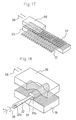
- Figures 17 and 18 are enlarged perspective views, with portions broken away, of main portions of the vacuum apparatus shown in Figure 16;
- Figure 19 is a side view of a reed of a water jet loom used in a weaving machine, which is a further example of the implement for a knitting, weaving or sewing machine in accordance with the present invention;
- Figure 20 is a section view taken along the line B-B in Figure 19;
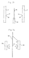
- Figure 21 is a section view of a vacuum apparatus used for forming, by sputtering, a coating on the reed of water jet loom shown in Figures 19 and 20;
- Figure 22 is a side view of an air jet loom used in a weaving machine;
- Figure 23 is a side view of a heald of a water jet loom used in a weaving machine;
- Figure 24 is a section view of main portions of a vacuum apparatus used for forming, by sputtering, a coating on the heald of water jet loom shown in Figure 23;
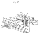
- Figure 25 is a perspective view of main portions of a needle and a tongue unit used in a warp knitting machine, which are still another examples of the implement for a knitting, weaving or sewing machine in accordance with the present invention; and
- Figure 26 is a plan view of main portions of needles and a warp inserting device used in a narrow-width fabric weaving machine, which are still further examples of the implement for a knitting, weaving or sewing machine in accordance with the present invention.
- First, the following description will discuss knitting, weaving and sewing elements in a circular knitting machine, a warp knitting machine, a weaving machine and a sewing machine. The knitting, weaving and sewing elements such as knitting needles, sinkers, guides and the like to be discussed in the following are made using, as the main material, a music wire stipulated in JISG 3502 or carbon steel stipulated in JISG4401, which is to be obtained by annealing at 250°C after hardening at 600 to 700°C.
- Fig. 6 shows an example of the implement for a knitting or sewing machine in accordance with the present invention and illustrates how a coating is formed on the knitting needle 1 shown in Fig. 2 by sputtering. As shown in Fig. 6, the knitting needle 1 is secured to a fixing stand 2 and target members 3, 3' of the Ta type are disposed in parallel with the knitting needle 1 at both sides thereof with a distance of 70 mm provided between each target member 3, 3' and the knitting needle 1. The ambient atmospheric pressure is reduced to about 10⁻³ Torr and argon gas is put to adjust the ambient atmospheric pressure to 10⁻² Torr. Then, the minus terminal of a DC power supply is connected to the target members 3, 3', while the plus terminal of 2000V or 400V, 5A is connected to a vacuum vessel (not shown). Then, the argon gas is ionized under glow discharge. The ions are sputtered on the Ta-type target members 3, 3' to spring out sputtering atoms, which are sticked to the surface of the knitting needle 1, thus forming a coating. Since each of the target members 3, 3' has a sufficiently great area as compared with the surface area of the knitting needle 1, the coating can be formed uniformly on the entire surface of the knitting needle 1. It is noted that a coating of 5µ was actually formed by sputtering for about 30 minutes. The coefficient of friction of a Ta-type amorphous metallic layer is from 0.05 to 0.15 which is smaller than 30% of that obtained by ion plating.
- Fig. 7 shows how a coating having two portions different in thickness from each other is formed on a sewing needle by the sputtering above-mentioned. A
sewing needle 5 having an arrangement as shown in Fig. 8 is secured to a fixing stand 7, andtarget members 4, 4' of the W-type are disposed in parallel with thesewing needle 5 at both sides thereof with a distance of 70 mm provided between eachtarget member 4, 4' and thesewing needle 5. A thickness adjusting plate 6 is disposed at the fixing stand 7. A vacuum vessel is adjusted in the same manner as above-mentioned. A DC power supply of 2000V or 400V is applied to the vacuum vessel and thetarget members 4, 4'. Since each of thetarget members 4, 4' has a sufficiently great area with respect to thesewing needle 5, sputtering atoms come in uniform collision with thesewing needle 5 at the entire surface thereof. By adjusting the angle of the adjusting plate 6, a coating portion having a thickness of 10µ is formed on thesewing needle 5 at thetip 8 thereof and around a hole 9 thereof, and a coating portion having a thickness of 1 to 3µ is formed on a stem 10 of thesewing needle 5. At this time, a voltage of 2000V, 0.8A or 400V, 5A is applied for 40 minutes, and the temperature of thesewing needle 5 during sputtering is 250°C. The coefficient of friction of the W-type amorphous metallic layer is from 0.05 to 0.15 which is less than 30% of that obtained by ion plating. - The following description will discuss implements used in a warp knitting machine as another examples of the present invention.
- Fig. 9 is a gland guide block to be mounted on a guide bar (not shown). The gland guide block has a holding
portion 21 made of a material composed of a tin alloy, and guidepieces 22 made of a steel material. As shown in an enlarged manner in Fig. 10, each of theguide pieces 22 is coated, at the entire outer peripheral surface thereof, with acoating 23 of an amorphous metallic layer. This amorphousmetallic layer 23 may be formed for example by sputtering with the use of Ta, W, titanium (Ti), zirconium (Zr), a titanium-tungsten alloy (TiW), titanium nitride (TiN) or the like. - Fig. 11 shows stitch
comb pieces 24 in a stitch comb block. Fig. 12 showsneedle pieces 25 in a needle block. Fig. 13 showsseparator pieces 26 in a separate block. Fig. 14 showssinker pieces 27 in a sinker block used in a tricot machine. Fig. 15 showsjacquard guide pieces 28 in a jacquard guide block used in a jacquard-raschel machine. Each of thesepieces coating 23 of an amorphous metallic layer likewise theguide piece 22 in Fig. 10. In Figs. 11 to 15, holdingportions 21 are disposed for holding the respective pieces. - Each
coating 23 of an amorphous metallic layer is formed by sputtering with the use of avacuum apparatus 30 shown in Fig. 16. Fig. 16 shows the state where thecoatings 23 of amorphous metallic layer are formed, by sputtering, on a plurality of guide pieces 22 (includingholes 22a) of a gland guide block shown in Fig. 9, which are simultaneously held by the holdingportion 21. Thecoatings 23 are not formed on those portions of theguide pieces 22 held by the holdingportion 21. - In Fig. 16, a
vessel 31 is so arranged as to resist an atmospheric pressure of at least 10⁻⁸ Torr. Thisvessel 31 has an argongas inlet port 32 and anexhaust port 33. Hung down from the ceiling of thevessel 31 is a hangingmember 34, under which a plurality ofguide pieces 22 are mounted. - As shown in Fig. 17, the
guide pieces 22 are disposed, between astationary rack 35 and a slidingrack 36, as held bypinions 37 meshed with theseracks rack 36 is moved back and forth in directions shown byarrows 38, thepinions 37 are rotated in both directions, causing theguide pieces 22 to be rotated in both directions shown byarrows 39. - As shown in Fig. 18, each of the
guide pieces 22 is inserted into aslit 37a in eachpinion 37 and secured by suitable fixing means such as a screw or securely held by a magnetic force by magnetizing thepinion 37. As shown in Fig. 16, thestationary rack 35 is supported at both ends thereof byslide receiving members 40, and one end of therack 35 is connected to aneccentric wheel 42 to be rotated by amotor 41. In Fig. 16, there are also disposed asupport stand 44 forming a cathode plate and a Ta-type target member 45. - A sputtering
power supply 46 has anode and cathode terminals respectively connected to thecathode plate 44 and thevessel 31. - In the arrangement above-mentioned, the inside of the
vessel 31 is reduced in pressure through theexhaust port 33 with the use of a vacuum pump, and thevessel 31 is filled with argon gas introudced through theinlet port 32 to adjust the atmospheric pressure in thevessel 31 to not greater than 10⁻⁸ Torr. When a DC voltage of 400V is applied to the sputteringpower supply 46, glow discharge is excited between thevessel 31 and thetarget member 45. At this time, the argon gas ions come in collision with thetarget member 45 to spring out the component atoms of thetarget member 45, which are sticked to the surfaces of theguide pieces 22 at the anode side. Theguide pieces 22 are forcibly rotated in a reciprocating manner by the back-and-front movement of the slidingrack 46. Accordingly, thecoatings 23 of amorphous metallic layer are uniformly formed on the entire surfaces of theguide pieces 22 including theholes 22a. - In the amorphous
metallic layers 23 thus formed, there are uniformly distributed crystal defects presenting no regularity in atomic configuration, so that no pin-holes are present. With the use of the Ta-type target member 45, the amorphousmetallic layers 23 can be provided with excellent wear resistance, toughness and corrosion resistance. In this embodiment, each amorphousmetallic layer 23 has bonding strength as large as 9 kg/mm², thus assuring very strong adhesive properties. - It is a matter of course that examples of the material of the
target member 45 include, in addition to metals of the Ta- and W-types above-mentioned, highly hard metals of the titanium (Ti), zirconium (Zr), titanium-tungsten alloy (Ti), and titanium nitride (TiN) types and so on. - Of course, other inert gas than the argon gas used in the example above-mentioned, may be used as the gas to be substituted with the air in the
vessel 31. - The following description will discuss examples of the implement used in a weaving machine with reference to the attached drawings.
- Fig. 19 shows a
reed 51 in a water jet loom. As shown in Fig. 20, thereed 51 has a rounded section in the form of an oval. It is bothlateral surfaces - In sputtering for the
water jet reed 51 above-mentioned, the inside of the vacuum vessel is reduced in pressure to 10⁻³ Torr and the vacuum vessel is then filled with argon gas to adjust the atmospheric pressure therein to 10⁻² Torr. As shown in Fig. 21, thereed 51 is secured onto a fixingstand 52 and target members (Ta: 50%, Fe: 35%, Ni: 5%, Cr: 10%) 4, 4' are disposed in parallel with thereed 51 at both sides thereof with a distance of 70 mm provided between eachtarget member 4, 4' and thereed 51. A DC voltage of 400V is applied across the vessel inner wall and thetarget members 4, 4' to generate glow discharge of argon. Ionized argon atoms are sputtered thetarget members 4, 4' to spring out sputtering atoms, which are then sticked to the surface of thereed 51. When such sputtering is conducted for about 40 minutes, a coating having a thickness of 5µ is formed. - Fig. 22 shows a reed 54 in an air jet loom. A coating similar to the coating above-mentioned was sticked to the reed 54 by sputtering similar to the sputtering above-mentioned.
- Fig. 23 shows, as a further example of the present invention, a
heald 60 of a water jet loom used in a weaving machine. Theheald 60 has an entire length of 300 mm, a width of 2 mm and a thickness of 0.2 mm, and is made of a resilient material of SUS403. Theheald 60 has at its center portion aslot 61, through which warp is to pass. Theheald 60 may be entirely uniformly coated with a coating, but the following description will discuss how to form a coating of which portion around theslot 61 has a thickness of 6 µ and other portions have a thickness of 1 to 3 µ. - Fig. 24 shows main portions of a vacuum apparatus used for forming a coating on the
heald 60 by sputtering.Target members 68, 68' having a length of about 60 mm are disposed at both sides of thecenter slot 61 with a distance of 50 mm provided between eachtarget member 68, 68' and theheald 60. Then, sputtering is carried out under the same conditions as those in the sputterings above-mentioned. - Since the
target members 68, 68' are short as compared with theheald 60, the majority of sputtering atoms inevitably reach theslot 61, while a small amount of atoms is sticked to the tip of theheald 60. When the coating thickness actually exceeds 5 µ, the highly hard coating is cracked when theheald 60 is strongly bent. Accordingly, it is sufficiently useful that the coating portion which coats the circumference of theslot 61 is made particularly thick and the coating portion which coats other portion than the circumference of theslot 61 is made thin but presents such effect as to provide good lubricating properties. - The following description will discuss the results of tests conducted on a conventional reed made of stainless steel (SUS-430) and a reed according to the present invention.
- In the tests, a water jet loom was operated at a speed of 800 times/minute to knit a plain knitted fabric using polyester warp of 50d with density of 100 yarns/inch and with weft beating density of 100 yarns/inch. With the conventional reed of stainless steel, scratches were observed on the reed at the time when the fabric was knitted by a length of 3000 m and the warp showed fluff at the time when the fabric was knitted by a length of 3500 m. On the other hand, no scratches were observed on the reed of the present invention even though the fabric was knitted by a length of more than 7000 m.
- Fig. 25 shows still another example of the implement for a knitting, weaving or sewing machine in accordance with the present invention. In Fig. 25, a
coating 23 of an amorphous metallic layer is formed on the surfaces of eachneedle 70 and eachtongue unit 71 used in a warp knitting machine. Fig. 26 shows a still further example of the implement for a knitting, weaving or sewing machine in accordance with the present invention. In Fig. 26, acoating 23 of an amorphous metallic layer is formed on the surface of each of weaving elements such as aneedle 80, aweft inserting device 81, aholder 82 and the like. In this example, too, there are produced similar effects to those produced in the examples above-mentioned. - In the implement for a knitting, weaving or sewing machine of the present invention, those portions thereof which come in contact and are rubbed with yarn at the time of knitting, weaving or sewing, are wholly or partially coated with coatings of an amorphous solid layer, thus minimizing the wear of such portions. This prevents the yarn from fluffing or being cut due to wear. Further, the corrosion-resisting properties of the coatings prevent the implement from being corroded due to yarn or installation environment. Further, each coating is made of an amorphous solid layer in which atomic configuration presents no regularity and crystal defects are uniformly distributed. Accordingly, the implement of the present invention is securely provided with toughness inevitably required for fulfilling the performance of the implement. Thus, the present invention can provide an implement for a knitting, weaving or sewing machine excellent in performance and durability.
Claims (9)
- An implement for a knitting, weaving or sewing machine of which a knitting, weaving or sewing element adapted to come in contact or be rubbed with yarn is mainly made of steel, said implement characterized in that said knitting, weaving or sewing element is wholly or partially coated with a coating of an amorphous solid layer.
- An implement for a knitting, weaving or sewing machine according to Claim 1, wherein the main component of the amorphous solid layer is composed of ceramics such as SiC, Al₂O₃, ZrO₂, Cr₂O₃ or the like.
- An implement for a knitting, weaving or sewing machine according to Claim 1, wherein the main component of the amorphous solid layer is highly hard metal of the tantalum or tungsten type.
- An implement for a knitting, weaving or sewing machine according to Claim 1, 2 or 3, wherein the coating has a portion having a thick amorphous solid layer, and a portion having a thin amorphous solid layer.
- An implement for a knitting, weaving or sewing machine according to Claim 4, wherein the coating is formed such that its portion having a thick amorphous solid layer and its portion having a thin amorphous solid layer are continuously formed.
- An implement for a knitting, weaving or sewing machine according to Claim 2, wherein that portion of the coating having a thick amorphous solid layer has a thickness of 0.1 to 5 µm.
- An implement for a knitting, weaving or sewing machine according to Claim 3, wherein that portion of the coating having a thick amorphous solid layer has a thickness of 1 to 10 µm.
- An implement for a knitting, weaving or sewing machine according to Claim 1, 2 or 3, wherein a plating layer is previously formed between the coating and the surface of a steel material forming the main body of the knitting, weaving or sewing element.
- An implement for a knitting, weaving or sewing machine according to Claim 1, 2 or 3, wherein the amorphous solid layer forming the coating is made by sputtering.
Applications Claiming Priority (6)
| Application Number | Priority Date | Filing Date | Title |
|---|---|---|---|
| JP147730/90 | 1990-06-05 | ||
| JP14773090A JPH0441755A (en) | 1990-06-05 | 1990-06-05 | Knitting tool for warp knitting machine and its production |
| JP17409890A JPH0465559A (en) | 1990-06-29 | 1990-06-29 | Tool coated with amorphous alloy for knitting or sewing machine and production thereof |
| JP174098/90 | 1990-06-29 | ||
| JP17588590 | 1990-07-02 | ||
| JP175885/90 | 1990-07-02 |
Publications (2)
| Publication Number | Publication Date |
|---|---|
| EP0485633A1 true EP0485633A1 (en) | 1992-05-20 |
| EP0485633A4 EP0485633A4 (en) | 1992-11-19 |
Family
ID=27319410
Family Applications (1)
| Application Number | Title | Priority Date | Filing Date |
|---|---|---|---|
| EP19910910628 Withdrawn EP0485633A4 (en) | 1990-06-05 | 1991-06-03 | Tool for knitting, weaving, and sewing machines |
Country Status (3)
| Country | Link |
|---|---|
| EP (1) | EP0485633A4 (en) |
| KR (1) | KR920702448A (en) |
| WO (1) | WO1991019031A1 (en) |
Cited By (7)
| Publication number | Priority date | Publication date | Assignee | Title |
|---|---|---|---|---|
| EP0558440A1 (en) * | 1992-02-24 | 1993-09-01 | Perfecta Schmid AG | Embroidery borer |
| FR2796402A1 (en) * | 1999-07-13 | 2001-01-19 | Grob Horgen Ag | HARNESS SYSTEM, AUTOMATIC INNER TENSIONING MACHINE FOR TREATING HARNESSES AND WEAVING MATERIAL FOR USING SUCH A SYSTEM |
| DE102005060235A1 (en) * | 2005-12-14 | 2007-06-21 | Groz-Beckert Kg | Part for a coating system comprising a metal body with flat and narrow sides with a metal coating useful for electroplating narrow sides of flat metal parts, e.g. with Cr coating |
| CN101348970B (en) * | 2007-07-20 | 2012-10-24 | 卡维可股份公司 | Procedure for manufacturing ladderproof fabrics |
| CN111201340A (en) * | 2017-08-03 | 2020-05-26 | 格罗兹-贝克特公司 | Textile machine tool component and method for producing a textile tool |
| EP3483319B1 (en) | 2017-11-09 | 2021-12-22 | Groz-Beckert KG | Textile tool with indicator film |
| EP4636148A1 (en) | 2024-04-15 | 2025-10-22 | Groz-Beckert KG | Warp knitting module with warp knitting tool and method for producing the warp knitting module |
Families Citing this family (1)
| Publication number | Priority date | Publication date | Assignee | Title |
|---|---|---|---|---|
| CN118727251B (en) * | 2024-09-04 | 2024-11-26 | 泉州师范学院 | Thread passing device in functional knitted fabric knitting machine |
Family Cites Families (3)
| Publication number | Priority date | Publication date | Assignee | Title |
|---|---|---|---|---|
| JPS5459450A (en) * | 1977-10-17 | 1979-05-14 | Toray Industries | Needle for processing fiber |
| JPS60162848A (en) * | 1984-01-30 | 1985-08-24 | オルガン針株式会社 | Knitting needle |
| JPS6241358A (en) * | 1985-08-16 | 1987-02-23 | ティーディーケイ株式会社 | Knitting needle |
-
1991
- 1991-06-03 WO PCT/JP1991/000767 patent/WO1991019031A1/en not_active Ceased
- 1991-06-03 KR KR1019920700177A patent/KR920702448A/en not_active Ceased
- 1991-06-03 EP EP19910910628 patent/EP0485633A4/en not_active Withdrawn
Non-Patent Citations (2)
| Title |
|---|
| No further relevant documents disclosed * |
| See also references of WO9119031A1 * |
Cited By (11)
| Publication number | Priority date | Publication date | Assignee | Title |
|---|---|---|---|---|
| EP0558440A1 (en) * | 1992-02-24 | 1993-09-01 | Perfecta Schmid AG | Embroidery borer |
| FR2796402A1 (en) * | 1999-07-13 | 2001-01-19 | Grob Horgen Ag | HARNESS SYSTEM, AUTOMATIC INNER TENSIONING MACHINE FOR TREATING HARNESSES AND WEAVING MATERIAL FOR USING SUCH A SYSTEM |
| BE1014165A5 (en) * | 1999-07-13 | 2003-06-03 | Grob Horgen Ag | HARNESS SYSTEM, AUTOMATIC INNER TENSIONING MACHINE FOR THE TREATMENT OF HARNESSES AND WEAVING MATERIAL FOR THE USE OF SUCH A SYSTEM. |
| DE102005060235A1 (en) * | 2005-12-14 | 2007-06-21 | Groz-Beckert Kg | Part for a coating system comprising a metal body with flat and narrow sides with a metal coating useful for electroplating narrow sides of flat metal parts, e.g. with Cr coating |
| DE102005060235B4 (en) * | 2005-12-14 | 2007-10-25 | Groz-Beckert Kg | System part and chrome plating process |
| DE102005060235C5 (en) * | 2005-12-14 | 2010-04-01 | Groz-Beckert Kg | System part and chrome plating process |
| CN101348970B (en) * | 2007-07-20 | 2012-10-24 | 卡维可股份公司 | Procedure for manufacturing ladderproof fabrics |
| CN111201340A (en) * | 2017-08-03 | 2020-05-26 | 格罗兹-贝克特公司 | Textile machine tool component and method for producing a textile tool |
| CN111201340B (en) * | 2017-08-03 | 2024-03-01 | 格罗兹-贝克特公司 | Textile machine tool components and methods for manufacturing textile tools |
| EP3483319B1 (en) | 2017-11-09 | 2021-12-22 | Groz-Beckert KG | Textile tool with indicator film |
| EP4636148A1 (en) | 2024-04-15 | 2025-10-22 | Groz-Beckert KG | Warp knitting module with warp knitting tool and method for producing the warp knitting module |
Also Published As
| Publication number | Publication date |
|---|---|
| WO1991019031A1 (en) | 1991-12-12 |
| EP0485633A4 (en) | 1992-11-19 |
| KR920702448A (en) | 1992-09-04 |
Similar Documents
| Publication | Publication Date | Title |
|---|---|---|
| CA1041881A (en) | Coated steel product and process of producing the same | |
| WO1991019031A1 (en) | Tool for knitting, weaving, and sewing machines | |
| GB1562572A (en) | Looper for tufting machines | |
| JP6029149B2 (en) | Manufacturing method of knitting needles | |
| JP2953673B2 (en) | Osa for high-speed loom | |
| US4822662A (en) | Machine parts with wear-resistant surface brought into contact with elongated fibrous member | |
| JP2574934Y2 (en) | Parts for knitting machines | |
| US5006367A (en) | Electroless coating method | |
| US5642632A (en) | Coated knitting parts of knitting machine | |
| TWI612184B (en) | Yarn guiding elements for textile machine with coating composite metal carbide ceramic electroplating layer and production method the same | |
| US5829240A (en) | Spinning ring having improved traveler bearing surface | |
| JPS6117518B2 (en) | ||
| US5546770A (en) | Knitting parts of knitting machine | |
| KR19980018557A (en) | Loom parts and looms using them | |
| JP2851568B2 (en) | How to increase the useful life of the seat bar | |
| JPH0441755A (en) | Knitting tool for warp knitting machine and its production | |
| JP5070629B2 (en) | Loom member and manufacturing method thereof | |
| US20220402017A1 (en) | Methods For Producing and Using a Textile Machine Tool Part | |
| GB2301119A (en) | Dents for reed in high-speed weaving machine,and method of manufacturing same | |
| US6119489A (en) | Knitting machine parts resistant to abrasion by yarn of cut-resistant fiber | |
| JPH07310259A (en) | Deformed reed and method for weaving narrow woven fabric with deformed reed | |
| JP2006257587A (en) | Stretchable warp knitted fabric | |
| HK40113313A (en) | Textile tools with wear-resistant layer | |
| JPH0519342Y2 (en) | ||
| JPH06200451A (en) | Abrasion-resistant dent and its production |
Legal Events
| Date | Code | Title | Description |
|---|---|---|---|
| PUAI | Public reference made under article 153(3) epc to a published international application that has entered the european phase |
Free format text: ORIGINAL CODE: 0009012 |
|
| 17P | Request for examination filed |
Effective date: 19920204 |
|
| AK | Designated contracting states |
Kind code of ref document: A1 Designated state(s): DE FR GB IT |
|
| A4 | Supplementary search report drawn up and despatched |
Effective date: 19920928 |
|
| AK | Designated contracting states |
Kind code of ref document: A4 Designated state(s): DE FR GB IT |
|
| STAA | Information on the status of an ep patent application or granted ep patent |
Free format text: STATUS: THE APPLICATION IS DEEMED TO BE WITHDRAWN |
|
| 18D | Application deemed to be withdrawn |
Effective date: 19940103 |