EP0485321B1 - Mixer - Google Patents
Mixer Download PDFInfo
- Publication number
- EP0485321B1 EP0485321B1 EP91630096A EP91630096A EP0485321B1 EP 0485321 B1 EP0485321 B1 EP 0485321B1 EP 91630096 A EP91630096 A EP 91630096A EP 91630096 A EP91630096 A EP 91630096A EP 0485321 B1 EP0485321 B1 EP 0485321B1
- Authority
- EP
- European Patent Office
- Prior art keywords
- mixing
- gap
- mixer
- bodies
- mixing gap
- Prior art date
- Legal status (The legal status is an assumption and is not a legal conclusion. Google has not performed a legal analysis and makes no representation as to the accuracy of the status listed.)
- Expired - Lifetime
Links
Images

Classifications
-
- G—PHYSICS
- G06—COMPUTING OR CALCULATING; COUNTING
- G06F—ELECTRIC DIGITAL DATA PROCESSING
- G06F3/00—Input arrangements for transferring data to be processed into a form capable of being handled by the computer; Output arrangements for transferring data from processing unit to output unit, e.g. interface arrangements
- G06F3/01—Input arrangements or combined input and output arrangements for interaction between user and computer
- G06F3/011—Arrangements for interaction with the human body, e.g. for user immersion in virtual reality
-
- B—PERFORMING OPERATIONS; TRANSPORTING
- B01—PHYSICAL OR CHEMICAL PROCESSES OR APPARATUS IN GENERAL
- B01F—MIXING, e.g. DISSOLVING, EMULSIFYING OR DISPERSING
- B01F25/00—Flow mixers; Mixers for falling materials, e.g. solid particles
- B01F25/40—Static mixers
- B01F25/438—Static mixers with movable slits formed between reciprocating surfaces
-
- G—PHYSICS
- G06—COMPUTING OR CALCULATING; COUNTING
- G06F—ELECTRIC DIGITAL DATA PROCESSING
- G06F3/00—Input arrangements for transferring data to be processed into a form capable of being handled by the computer; Output arrangements for transferring data from processing unit to output unit, e.g. interface arrangements
- G06F3/01—Input arrangements or combined input and output arrangements for interaction between user and computer
- G06F3/03—Arrangements for converting the position or the displacement of a member into a coded form
- G06F3/033—Pointing devices displaced or positioned by the user, e.g. mice, trackballs, pens or joysticks; Accessories therefor
Definitions
- This invention relates to a new mixing system, and more particularly to a new apparatus and a new method for more intimately mixing a premix or preliminary mixture of materials, especially polymeric materials.
- Shear mixing is a highly dispersive type of mixing. It is to be distinguished from distributive mixing which commonly consists of stirring powdery ingredients or materials together. Highly efficient shear mixing effectively converts a distributive mixture into one exhibiting more or less uniform properties throughout the mass thereof, whereas in a distributive mixture the individual component properties are usually quite evident when the distributive mixture is subjected to testing.
- shear mixing apparatus is relatively complex and expensive. It is useful for large volume shear mixing, but not for the shear mixing of laboratory quantities for experimental or test purposes. Known apparatus designed especially for laboratory shear mixing is relatively expensive (about six figures in cost), and effective use of it still requires a relatively large quantity of material for treatment. Much desired has been a relatively economical and effective shear mixing apparatus and methods capable of scaled down economical laboratory shear mixing for low gram quantities as well as for somewhat larger laboratory quantities as experimental progress is made. It is to a solution of this problem that this invention is primarily directed.
- a very significant benefit of the invention making it especially valuable for laboratory use is the ease by which apparatus of the invention can be dismantled and cleaned--using, of course, an appropriate solvent for the residuum of the polymeric mass to be washed away.
- the invention provides relatively economical apparatus and method for more intimately mixing a polymeric premix mass.
- a method of mixing a polymeric mass comprising pushing the polymeric mass through a first mixing gap defined by spaced apart wall surfaces in a first linear direction, said method including the step of pushing the mass in a second linear direction through a second mixing gap defined by spaced apart wall surfaces, said second linear direction being parallel and opposite to said first linear direction, and said method including the additional step of simultaneously increasing the length of the mixing gaps as the mass is pushed therethrough.
- the method may include a preliminary step of assembling apparatus to form said spaced apart wall surfaces at a spacing no greater than 1 mm for said mixing gaps, and the method may also include the step of moving one wall surface of each of said mixing gaps in a direction opposite to the direction of movement of the mass through said gaps.
- a mixer for carrying out the method of mixing comprising a first body having a primary wall surface for said first mixing gap, and a second body having an opposing wall surface for said first mixing gap, said second body being oriented to said first body so that said opposing wall surface is in parallel spaced relationship to said primary wall surface, said first and second bodies being linearly slideable with respect to each other for effecting contractive movement of said first and second bodies together in a linear direction parallel with said primary and opposing wall surfaces as mixing is accomplished in said first mixing gap, said contractive movement being effective to lengthen the linear length of said first mixing gap, wherein a premix space is defined in said first body and an intermediate space is defined in said second body, and wherein said first mixing gap provides flow communication from said premix space to said intermediate space in a first direction during said contractive movement of said first and second bodies together, said mixer having said second mixing gap defined by spaced primary and opposing wall surfaces through which material in said intermediate space exits said intermediate space in a second direction during said contractive movement
- the second of the bodies may include a plunger for pushing material from said premix space through said first mixing gap.
- the opposing wall surface for said first mixing gap may be carried on said plunger and move in a direction opposite to that of the movement of material through said first mixing gap during said contractive movement of said first and second bodies together.
- the plunger may include a surface which forms one of the spaced wall surfaces of said first mixing gap.
- the width of the first mixing gap can be selected to be no greater than 1 mm.
- said premix space is an annular space; said first body defining said premix space has a terminal base wall, an outer annular housing wall extending from said terminal base wall on the radially outer side of said premix space, and a radially inner annular base plunger extending from said terminal base wall on the radially inner side of said premix space, said base plunger defining at its radially outer side said primary wall surface for said first mixing gap and defining at its radially inner side said opposing wall surface for said second mixing gap; and said intermediate space is annular and said second body defining said intermediate space has a terminal limit wall, an annular primary plunger extending from said terminal limit wall on the radially outer side of said intermediate space, and an annular core wall extending from said terminal limit wall on the radially inner side of said intermediate space, said annular primary plunger defining at its radially outer side a surface for sealing relationship with said housing wall of said first body and defining at its radially inner side said opposing wall surface for said first mixing gap, said
- means can be provided for pressing said first and second bodies contractively together to cause said primary plunger of said second body to push material out of said premix space through said first mixing gap into said intermediate space while said annular base plunger simultaneously moves into said intermediate space and contributes to the pushing of material out of said intermediate space through said second mixing gap, said opposing walls of said first and second mixing gaps being moved in a direction opposite to the passage of material through said gaps as said bodies are pressed together.
- the axial direction length of said primary wall surface and said opposing wall surface for said first mixing gap may be each at least 25 times the width of said first mixing gap, and the width of said first and second mixing gaps between the primary and opposing wall surfaces thereof is optionally no greater than 1 mm.
- the preferred mixer of the invention comprises two bodies 10 and 20 which sometimes are called cups. Each cup may consist of a single piece or be assembled from several individual parts. It is convenient to refer to the first body 10 as a base or foundation or lower or bottom body or cup. Thus, the second body 20 is distinguished by use of terms such as the upper or top or auxiliary body or cup.
- the two bodies fit together in a cooperative manner and suitably are characterized as being mateable. They are not perfect mirror complement images of each other, although they are close to that if one ignores differences in the size of some annular parts and in some refinements of preferred detail.
- the first body defines an annular premix space 11 having a terminal base wall 12 that provides a lower bottom interior or terminal surface 13 for the axial or longitudinal direction of space 11.
- the first body is also shaped to define an outer annular housing wall 14 extending from the terminal base wall 12 on one side of the annular premix space 11. Further, it defines an inner annular base plunger 15 extending from the terminal base wall on the other side of the annular premix space.
- the inner annular plunger 15 is radially inward from the radially outward housing wall 14.
- the plunger 15 defines at its outer perimeter or radially outer side a primary wall surface 16 for a linear first gap 100 and defines at its inner perimeter or radially inner side an opposing wall surface 17 for a linear second gap 200.
- the annular plunger 15 preferably has a piston or flattened end 18.
- the illustrated first body is generally cylindrical at its outer surface and suitably is flat and planar at its bottom exterior surface, although other outer or exterior configurations may be suitable.
- the second body 20 is shaped to define an annular intermediate space 21 having a terminal limit wall 22 that provides an interior limit surface 23 for the axial direction or longitudinal direction of space 21.
- the shape of the second body defines an annular primary plunger 24 and an inner annular core wall 25.
- the radially outer annular primary plunger 24 extends from the terminal limit wall 22 on one side or radially outer side of the intermediate space 21.
- the inner annular core wall 25 extends from the terminal limit wall 22 on the other or radially interior side of the intermediate space 21.
- Core wall 25 may be hollow or comprise an axially centered cylindrical shaft or the like. It defines at its outer perimeter or outer side the annular first or primary wall surface 26 of the linear second gap 200.
- the annular primary plunger 24 defines at its radially outer side a surface 27 for sealing relationship to the interior surface of the housing wall 14 of the first body, and defines at its radially inner side the opposing wall surface 28 for the linear first gap 100.
- first or primary wall surface 16 for the first gap 100 is carried on the first body 10 or base cup
- second or opposing wall surface 28 for the first gap 100 is carried on the second body 20 or upper cup
- first or primary wall surface 26 of the second gap 200 is carried on the second body or upper cup
- second or opposing wall surface 17 for the second gap 200 is carried on the first body 10 or base.
- the gaps 100 and 200 are annular and their linear length is in the axial or longitudinal direction (i.e., perpendicular to the radial direction). The width of the gaps is in the radial direction. Further to be noted is that, as the first and second bodies are pressed together, the length of each gap is increased.
- each body carries an annular plunger.
- the annular plunger carried on the first or base body is suitably characterized as a base plunger 15 whereas the annular plunger carried on the second or upper body is suitably characterized as a primary plunger 24.
- base plunger functions on the order of a flow path guide since materials undergoing mixing flow on each side of it, but in opposite directions, while at the same time the piston end 18 of the base plunger (on contraction of the first and second bodies) presses against material in the intermediate space, constantly reducing the size of the intermediate space.
- the primary plunger 24 of the second body provides the frontal or primary piston end 29, and piston end 29 functions as the primary means for the pushing or forcing of materials through the gaps of the mixer as the bodies are contracted or pressed together.
- any suitable means may be employed for the purpose of pressing the first and second bodies contractively together. Pressing the bodies together effects the mixing operation in a manner such that a premix in flowable or molten form in the premix space 11 is passed or travels or is forced through the first gap 100 as a result of the annular primary plunger of the second body moving into the premix space and thereby pushing or forcing material of the premix through the first gap 100 into the intermediate space 21.
- Continued contraction of the first and second bodies in a mating relationship effectively causes material in the intermediate space 21 to travel through the second gap 200 as a result of the annular base plunger 15 on the first body moving into the intermediate space 21 or, stated vice-versa, as a result of the intermediate space terminal limit wall 23 descending upon the base plunger 15. Regardless of how one views it, the size of the intermediate space is reduced and material exits from the intermediate space through the second gap and out the extrudate exit 30.
- Means for pressing the first and second bodies together in a mating relationship may comprise or consist of placing a weight on the top surface of the second body after orienting the same as illustrated in Fig. 3.
- the force of the weight should of course be sufficient to effect contraction of the bodies and forced flow of the material to be mixed through the gaps.
- Other suitable means to effect contraction may comprise screw operated compression devices or hydraulically operated compression devices or any device whatsoever that can provide the compressive forces to effect contraction of the bodies and thereby push or force material mass through the gaps formed by the bodies.
- FIG. 4 illustrates but one of a wide variety of ways for affecting contractive forces on the two bodies of the mixer.
- two rods 41 and 42 extend upright from a machine bed 43 and serve as the guides for a crosshead 44 as it is lowered.
- a vessel or extrudate receiver 31 for collecting the material leaving the mixer is centered in a helical spring 45 extending upwards from the machine bed.
- a wood block 46 At the top of the helical spring is a wood block 46 for supporting a first or base or lower body 10 of the mixer.
- the wood block 46 suitably has a hole or opening in its center to allow extrudate to drop from exit 30 of base body 10 into the collecting vessel 31.
- a wood block 47 is suitably placed between the upper surface of the second body 20 or upper cup of the mixer and the crosshead 44.
- a locking means or threaded friction pin 48 may be employed to hold the crosshead 44 at a predetermined location along the guide rods after the crosshead is lowered against spring 45.
- the spring 45 then effects a gradual and smooth compressive force on the bodies 10 and 20 to effect their contraction together.
- Illustrated also in Fig. 4 is a mass 50 surrounding the base 10 or lower body of the mixer. This mass suitably comprises a jacket.
- the jacket suitably is equipped with electrical resistent heating elements at its inner portion nearest the first body 10 of the mixer.
- the jacket of mass 50 may consist of heat insulative material, in which case the jacket is wrapped around the mixer in a manner to retain the heat of preheated mixer bodies 10 and 20.
- Any of a variety of heating means may be employed to maintain the mixer bodies at temperatures those skilled in the art recognize to be satisfactory or needed for the material or mass they select for treatment in the mixer.
- Resistance heating elements may be incorporated as part of the bodies; heated fluids may be circulated through passageways formed in the bodies. Higher temperatures may be used where the premix consists of a polymer and plasticizer without any catalyst or hardener. Where catalysts or hardeners are in the premix, the temperature and time of exposure should be limited so as to avoid triggering those reactions. Elevated temperatures desirably reduce the viscosity of the material being treated and thereby reduce the force needed to for contractive movement of the bodies.
- gaps 100 and 200 should not exceed about 1 millimeter for the most effective practice of shear mixing according to the invention, although a width for the gaps up to about 2 millimeters might give satisfactory results under rare circumstances such as for exceedingly highly polymerized components where a relatively low degree of shear mixing is to be accomplished but yet a satisfactory shear mixing operation is considered important.
- gap widths even as small as 0.1 millimeter (e.g., the micrometer range) can be useful, and especially useful for the shear mixing of low viscosity masses of materials, whether that low viscosity is characteristic of the mass at normal room temperature or is achieved by employing by elevated temperatures for the mixing step.
- a convenient gap width for the shear mixing of a variety of masses of polymeric materials is about 0.5 millimeter.
- the design of the bodies permits, for the first time insofar as known, effective shear mixing of extremely small experimental masses of materials.
- a premix mass totaling as few as 5 grams, or even possibly less may be shear mixed using the teachings of the invention.
- premix masses subjected to shear mixing will be on the order 7 or 10 or 15 grams or possibly even 25 or 30 grams. Such amounts still fall in the low quantity category not easily shear mixed using any earlier known equipment.
- even larger premix masses may be shear mixed using the teachings of the invention.
- the invention may be used to shear mix masses even in excess of 100 grams or more.
- the primary benefit of the invention however is that it provides a shear mixing system sorely needed for the shear mixing of small masses for laboratory pre-testing and experimental purposes.
- the first and second bodies forming the key elements for the practice of the invention may be fabricated from metal such as steel or any other suitable metal in sizes about the size of or smaller than a clenched fist.
- a test apparatus consisting of the upper and lower bodies illustrated in the Fig. 3 has been constructed to have overall external dimensions of about 8 centimeters (about 3 inches) in height--measured with the upper body or cup fully contracted into the lower body or cup--and about 6 centimeters (about 2.5 inches) for the outer diameter of the lower body or cup. It will therefore readily be seen that the invention permits convenient shear mixing with exceedingly small elements of apparatus, quite literally about the size as illustrated in Figs. 1 through 3.
- the linear length of the gaps 100 and 200 does increase as the two bodies of the mixer are contracted or pushed together.
- the minimum or shortest linear length for shear mixing should be no less than 25 times the width of the gaps and most preferably is much more. As the bodies are pushed together, the linear length of each gap increases and the final material passing through the gaps is subjected to shear mixing in each gap over a length of at least 50 times the width of a gap.
- the length of the first or primary wall surface 16 of the first gap 100 (between the interior surface 13 of base wall 12 and the piston end surface 18 of that first wall 16) should be equal to or substantially equal to the linear length of the opposing wall surface 28 for the first gap (between the piston 29 of that opposing wall and the limit surface 23 of the limit wall 22).
- the linear length of the first wall surface 16 and the opposing wall 28 in every instance should exceed about 25 times the width of gap 100 and usually will exceed 50 times its width and most preferably will exceed 100 times its width. That linear length may be greatly extended so as to even exceed 200 or more times the width of the first gap.
- the widths of the first and second gaps are substantially equal, but the width of one gap may be varied from the width of the other.
- the width of the first gap 100 may suitably be larger than the width of the second gap 200 for the shear mixing of a variety of polymeric material. Under such circumstances, the shear mixing effected during the passage of the materials through the first gap might be looked upon as but a prelude to the shear mixing occuring in the second gap.
- Either or both of the side surfaces forming a gap may be relatively smooth and suitably are relatively smooth.
- shear mixing may be enhanced by forming those surfaces with a design of relatively minute irregularities.
- This principle is illustrated in Figs. 1 and 2 by a schematic showing of parallel lines 32 that represent small grooves lying in the transverse direction (circumferential direction) to the passage of material through the gaps.
- Another illustrative pattern of minute irregularities is represented by a cross-hatching or X pattern 33 of grooved elements or striations.
- a minute pattern of irregularities can contribute to effective shear mixing, but such a pattern is not always critically required.
- a four component system was selected for experimental purposes.
- the four component system consisted of gram quantities of a carboxylated polyester resin and two Bis-phenol A based epoxy resins in an approximate mass ratio of 70/15/15, plus a milligram quantity of cross-linking or curing catalyst. These components were ground together with a laboratory grinder to fine powders.
- An illustrative Differential Scanning Calorimetry (DSC) analysis for this mixture (not subjected to shear mixing) is illustrated by the plot of Fig. 5.
- the plot is that of the Heat Flow in Watts per gram (W/g) against temperature in degrees Celsius.
- Three distinct and separate drops or depressions representing the glass transition temperatures (Tg) of the three resin components are evident. The exact glass transition temperatures are not important; the only thing important in the illustration of Fig. 5 is that each resin component exhibited its distinct glass transition temperature.
- This four component mixture is altered favorably (but without triggering catalytic action) by shear mixing using a known commercially available laboratory extruder (i.e., one wherein a screw is rotated to force material forwardly for shearing between the screw and fixed housing walls).
- a known commercially available laboratory extruder i.e., one wherein a screw is rotated to force material forwardly for shearing between the screw and fixed housing walls.
- the result of this is illustrated by the plot of Fig. 6, showing a single glass transition temperature for the three resin system. Again, the exact glass transition temperature is not important for purposes here.
- the only thing important for purposes here is that the shear mixing using an old known shear mixer converted the four component system into what might be called a uniform mass exhibiting at least some properties commonly looked upon as being characteristic of a single component system.
- the mixer bodies of the invention employed in this test were of a size as discussed specifically above--a size close to that literally illustrated in the drawings. They were formed of steel. The steel bodies were preheated to a selected processing temperature of 125 degrees Celsius. That temperature was insufficient to trigger catalytic action during the shear mixing of the four component system in view of the moderate thermal exposure time of treatment (about 1.5 minutes total processing time for a 10 gram premix).
- the premix of the four component system was placed in the premix space and the upper body or second body was then inserted into the lower one in the posture or orientation illustrated in Fig. 3. (It was found unnecessary to continue heating during processing because the heat stored in the metal was sufficient to melt the resins of the four component system and keep them molten during the short processing time. Several tests were conducted using varying quantities of premix, namely 7, 10, and 15 gram amounts.)
- the two bodies were then placed in the assembly illustrated in Fig. 4, with an insulating jacket employed.
- the movable crosshead was lowered at maximum speed (about 50 cm/min.) and stopped and locked in position when the applied load was approximately 6.7 kilonewtons (kN) or about 1500 pounds force (lbf).
- the spring had a stiffness of about 49kN/m (250 lbf/in.). The procedure to this point took about 45 to 60 seconds and extrusion did not occur during this time.
- the compressed spring effected a gradual and smooth driving of the two bodies into one another which in turn forced the melt in the premix chamber up through the first gap into the intermediate space of the upper body and then down through the second gap and out the lower opening or extrudate exit.
- the shear mixed sample was collected in the beaker underneath the mixer.
- the hot mixer body parts were disassembled and cooled in dry ice and soaked in acetone for cleaning.
- the first material to leave the mixer has the least degree of the shear mixing due to the initially relatively shorter gap lengths. As the gaps increase in length on contractive movement of the two bodies together, the degree of shear mixing increases. The last material to leave the mixer is subjected to the longest passage through the gaps of the mixer and is therefore the most thoroughly shear mixed portion.
- the internal pressure may vary from a pressure as low as about one Megapascal (Mpa) or 150 pounds force per square inch for low viscosity or thin materials up to possibly as much as 15 Mpa or 2,200 pounds force per square inch for mixtures of highly polymerized resins and high viscosity masses.
- Mpa Megapascal
- the selection of the degree of force is a matter for the judgment of those skilled in the art.
Landscapes
- Engineering & Computer Science (AREA)
- General Engineering & Computer Science (AREA)
- Theoretical Computer Science (AREA)
- Chemical & Material Sciences (AREA)
- Human Computer Interaction (AREA)
- Physics & Mathematics (AREA)
- General Physics & Mathematics (AREA)
- Dispersion Chemistry (AREA)
- Chemical Kinetics & Catalysis (AREA)
- Processing And Handling Of Plastics And Other Materials For Molding In General (AREA)
- Confectionery (AREA)
Abstract
Description
- This invention relates to a new mixing system, and more particularly to a new apparatus and a new method for more intimately mixing a premix or preliminary mixture of materials, especially polymeric materials.
- The teachings of the invention are especially useful for the shear mixing of polymeric materials. Shear mixing is a highly dispersive type of mixing. It is to be distinguished from distributive mixing which commonly consists of stirring powdery ingredients or materials together. Highly efficient shear mixing effectively converts a distributive mixture into one exhibiting more or less uniform properties throughout the mass thereof, whereas in a distributive mixture the individual component properties are usually quite evident when the distributive mixture is subjected to testing.
- Significant value and benefits arise from converting a premix of relatively distributive character into a shear mixed mass, and this is especially evident in the polymeric or plastics art. The dispersive effects of shear mixing are frequently desired to provide an improved and uniform quality for a polymer or mixture of polymers mixed with other materials or ingredients such as plasticizers, extenders, curing or cross-linking agents, and almost any other component or ingredient (even pigments) as those of skill in polymer compounding art may desire. Effective shear mixing reaches down to the molecular level, pulling and stretching polymeric molecules and parts and intertwining them with other components of the mass being shear mixed.
- Thus intimate mixing of ingredients or materials is accomplished by the invention, usually and preferably with some type of shearing action.
- It is also acknowledged that shear mixing of polymer masses as such is old technology. However, insofar as is known, the apparatus and methods employed in shear mixing as heretofore conducted are vastly different from the apparatus and methods of this invention. Heretofore known commercially available shear mixing apparatus is relatively complex and expensive. It is useful for large volume shear mixing, but not for the shear mixing of laboratory quantities for experimental or test purposes. Known apparatus designed especially for laboratory shear mixing is relatively expensive (about six figures in cost), and effective use of it still requires a relatively large quantity of material for treatment. Much desired has been a relatively economical and effective shear mixing apparatus and methods capable of scaled down economical laboratory shear mixing for low gram quantities as well as for somewhat larger laboratory quantities as experimental progress is made. It is to a solution of this problem that this invention is primarily directed.
- A very significant benefit of the invention making it especially valuable for laboratory use is the ease by which apparatus of the invention can be dismantled and cleaned--using, of course, an appropriate solvent for the residuum of the polymeric mass to be washed away.
- The invention provides relatively economical apparatus and method for more intimately mixing a polymeric premix mass.
- According to the invention there is provided a method of mixing a polymeric mass comprising pushing the polymeric mass through a first mixing gap defined by spaced apart wall surfaces in a first linear direction, said method including the step of pushing the mass in a second linear direction through a second mixing gap defined by spaced apart wall surfaces, said second linear direction being parallel and opposite to said first linear direction, and said method including the additional step of simultaneously increasing the length of the mixing gaps as the mass is pushed therethrough.
- The method may include a preliminary step of assembling apparatus to form said spaced apart wall surfaces at a spacing no greater than 1 mm for said mixing gaps, and the method may also include the step of moving one wall surface of each of said mixing gaps in a direction opposite to the direction of movement of the mass through said gaps.
- In further accordance with the invention there is provided a mixer for carrying out the method of mixing, comprising a first body having a primary wall surface for said first mixing gap, and a second body having an opposing wall surface for said first mixing gap, said second body being oriented to said first body so that said opposing wall surface is in parallel spaced relationship to said primary wall surface, said first and second bodies being linearly slideable with respect to each other for effecting contractive movement of said first and second bodies together in a linear direction parallel with said primary and opposing wall surfaces as mixing is accomplished in said first mixing gap, said contractive movement being effective to lengthen the linear length of said first mixing gap, wherein a premix space is defined in said first body and an intermediate space is defined in said second body, and wherein said first mixing gap provides flow communication from said premix space to said intermediate space in a first direction during said contractive movement of said first and second bodies together, said mixer having said second mixing gap defined by spaced primary and opposing wall surfaces through which material in said intermediate space exits said intermediate space in a second direction during said contractive movement of said first and second bodies together, said second said first and second bodies together, said second direction being opposite and essentially parallel to said first direction.
- The second of the bodies may include a plunger for pushing material from said premix space through said first mixing gap. The opposing wall surface for said first mixing gap may be carried on said plunger and move in a direction opposite to that of the movement of material through said first mixing gap during said contractive movement of said first and second bodies together. The plunger may include a surface which forms one of the spaced wall surfaces of said first mixing gap. The width of the first mixing gap can be selected to be no greater than 1 mm.
- In one advantageous embodiment said premix space is an annular space; said first body defining said premix space has a terminal base wall, an outer annular housing wall extending from said terminal base wall on the radially outer side of said premix space, and a radially inner annular base plunger extending from said terminal base wall on the radially inner side of said premix space, said base plunger defining at its radially outer side said primary wall surface for said first mixing gap and defining at its radially inner side said opposing wall surface for said second mixing gap; and said intermediate space is annular and said second body defining said intermediate space has a terminal limit wall, an annular primary plunger extending from said terminal limit wall on the radially outer side of said intermediate space, and an annular core wall extending from said terminal limit wall on the radially inner side of said intermediate space, said annular primary plunger defining at its radially outer side a surface for sealing relationship with said housing wall of said first body and defining at its radially inner side said opposing wall surface for said first mixing gap, said core wall defining at its radially outer side said primary wall surface for said second mixing gap.
- Additionally, means can be provided for pressing said first and second bodies contractively together to cause said primary plunger of said second body to push material out of said premix space through said first mixing gap into said intermediate space while said annular base plunger simultaneously moves into said intermediate space and contributes to the pushing of material out of said intermediate space through said second mixing gap, said opposing walls of said first and second mixing gaps being moved in a direction opposite to the passage of material through said gaps as said bodies are pressed together.
- The axial direction length of said primary wall surface and said opposing wall surface for said first mixing gap may be each at least 25 times the width of said first mixing gap, and the width of said first and second mixing gaps between the primary and opposing wall surfaces thereof is optionally no greater than 1 mm.
- Still further benefits and advantages and features of the invention will be evident as this description proceeds.
-
- Fig. 1 is a schematic perspective view of a first body for mixing apparatus of the invention;
- Fig. 2 is a schematic perspective view of a second body for the mixing apparatus;
- Fig. 3 is a schematic side view, partially in section, of the first and second bodies of the mixing apparatus in connected condition at or near an early stage of the contractive movement of the same together for mixing;
- Fig. 4 is a schematic side view of one suitable apparatus for effecting contractive force or pressures on the first and second bodies;
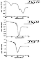
- Fig. 5 is a plot illustrating the three glass transition temperatures for the three individual resin components of a four component polymer system mechanically mixed in powder form, before any shear mixing;
- Fig. 6 is a plot illustrating the single glass transition temperature for the same four component system after being shear mixed using a commercially available laboratory extruder; and
- Fig. 7 is a plot illustrating the single glass transition temperature for the same four component system after being shear mixed using the mixer of this invention.
- Referring particularly to Figs. 1, 2 and 3, the features and characteristics of the preferred mixer of the invention will first be described. It comprises two
bodies first body 10 as a base or foundation or lower or bottom body or cup. Thus, thesecond body 20 is distinguished by use of terms such as the upper or top or auxiliary body or cup. The two bodies fit together in a cooperative manner and suitably are characterized as being mateable. They are not perfect mirror complement images of each other, although they are close to that if one ignores differences in the size of some annular parts and in some refinements of preferred detail. The use of terms such as upper or lower or top or bottom in describing the two bodies should not be construed to mean that the orientation of the two bodies during a mixing operation must always be as illustrated in Fig. 3. It is possible to effect the contraction employed in the mixing operation when the bodies are oriented in a position upside down from that illustrated in Fig. 3 or in any angular or even lateral or horizontal condition. By far the most preferred orientation, however, is illustrated in Fig. 3. - The first body defines an annular premix space 11 having a
terminal base wall 12 that provides a lower bottom interior orterminal surface 13 for the axial or longitudinal direction of space 11. The first body is also shaped to define an outerannular housing wall 14 extending from theterminal base wall 12 on one side of the annular premix space 11. Further, it defines an innerannular base plunger 15 extending from the terminal base wall on the other side of the annular premix space. The innerannular plunger 15 is radially inward from the radiallyoutward housing wall 14. Theplunger 15 defines at its outer perimeter or radially outer side aprimary wall surface 16 for a linearfirst gap 100 and defines at its inner perimeter or radially inner side anopposing wall surface 17 for a linearsecond gap 200. Theannular plunger 15 preferably has a piston or flattenedend 18. It should be noted that the illustrated first body is generally cylindrical at its outer surface and suitably is flat and planar at its bottom exterior surface, although other outer or exterior configurations may be suitable. Most ideally the walls, and particularly the surfaces of the annular walls forming the gaps, are cylindrical throughout the structure of the first body. Variations from purely cylindrical surfaces for the annular walls are possible, provided the gap surfaces at each radial orientation are axially parallel; and it will be evident that if one body is formed, complementary and cooperative variations then should be built into the other body. - The
second body 20 is shaped to define an annularintermediate space 21 having aterminal limit wall 22 that provides aninterior limit surface 23 for the axial direction or longitudinal direction ofspace 21. The shape of the second body defines an annularprimary plunger 24 and an innerannular core wall 25. The radially outer annularprimary plunger 24 extends from theterminal limit wall 22 on one side or radially outer side of theintermediate space 21. The innerannular core wall 25 extends from theterminal limit wall 22 on the other or radially interior side of theintermediate space 21.Core wall 25 may be hollow or comprise an axially centered cylindrical shaft or the like. It defines at its outer perimeter or outer side the annular first orprimary wall surface 26 of the linearsecond gap 200. The annularprimary plunger 24 defines at its radially outer side asurface 27 for sealing relationship to the interior surface of thehousing wall 14 of the first body, and defines at its radially inner side the opposingwall surface 28 for the linearfirst gap 100. Apiston end surface 29, preferably flat, is on theprimary plunger 24. - At this point it should be noted that the first or
primary wall surface 16 for thefirst gap 100 is carried on thefirst body 10 or base cup, whereas the second or opposingwall surface 28 for thefirst gap 100 is carried on thesecond body 20 or upper cup. Similarly, the first orprimary wall surface 26 of thesecond gap 200 is carried on the second body or upper cup, whereas the second or opposingwall surface 17 for thesecond gap 200 is carried on thefirst body 10 or base. Thegaps - It has been stated above that each body carries an annular plunger. The annular plunger carried on the first or base body is suitably characterized as a
base plunger 15 whereas the annular plunger carried on the second or upper body is suitably characterized as aprimary plunger 24. The distinction is better appreciated when one realizes that the "base plunger" functions on the order of a flow path guide since materials undergoing mixing flow on each side of it, but in opposite directions, while at the same time thepiston end 18 of the base plunger (on contraction of the first and second bodies) presses against material in the intermediate space, constantly reducing the size of the intermediate space. It thus functions as a "plunger" in the sense of pushing or forcing material out of (i.e., to leave) the intermediate space as it relentlessly enters the intermediate space and reduces the size of that space on continued contractive movement of the two bodies together. Theprimary plunger 24 of the second body provides the frontal orprimary piston end 29, and piston end 29 functions as the primary means for the pushing or forcing of materials through the gaps of the mixer as the bodies are contracted or pressed together. - Mixed material exits from the mixer at a central location illustratively defined by opposing
wall surface 17, and this is suitably characterized as anextrudate exit 30. - Any suitable means may be employed for the purpose of pressing the first and second bodies contractively together. Pressing the bodies together effects the mixing operation in a manner such that a premix in flowable or molten form in the premix space 11 is passed or travels or is forced through the
first gap 100 as a result of the annular primary plunger of the second body moving into the premix space and thereby pushing or forcing material of the premix through thefirst gap 100 into theintermediate space 21. Continued contraction of the first and second bodies in a mating relationship effectively causes material in theintermediate space 21 to travel through thesecond gap 200 as a result of theannular base plunger 15 on the first body moving into theintermediate space 21 or, stated vice-versa, as a result of the intermediate spaceterminal limit wall 23 descending upon thebase plunger 15. Regardless of how one views it, the size of the intermediate space is reduced and material exits from the intermediate space through the second gap and out theextrudate exit 30. - Means for pressing the first and second bodies together in a mating relationship may comprise or consist of placing a weight on the top surface of the second body after orienting the same as illustrated in Fig. 3. The force of the weight should of course be sufficient to effect contraction of the bodies and forced flow of the material to be mixed through the gaps. Other suitable means to effect contraction may comprise screw operated compression devices or hydraulically operated compression devices or any device whatsoever that can provide the compressive forces to effect contraction of the bodies and thereby push or force material mass through the gaps formed by the bodies.
- It is accordingly stressed that Fig. 4 illustrates but one of a wide variety of ways for affecting contractive forces on the two bodies of the mixer. In Fig. 4, two
rods 41 and 42 extend upright from amachine bed 43 and serve as the guides for acrosshead 44 as it is lowered. A vessel or extrudate receiver 31 for collecting the material leaving the mixer is centered in ahelical spring 45 extending upwards from the machine bed. At the top of the helical spring is awood block 46 for supporting a first or base orlower body 10 of the mixer. Thewood block 46 suitably has a hole or opening in its center to allow extrudate to drop fromexit 30 ofbase body 10 into the collecting vessel 31. A wood block 47 is suitably placed between the upper surface of thesecond body 20 or upper cup of the mixer and thecrosshead 44. A locking means or threadedfriction pin 48 may be employed to hold thecrosshead 44 at a predetermined location along the guide rods after the crosshead is lowered againstspring 45. Thespring 45 then effects a gradual and smooth compressive force on thebodies mass 50 surrounding the base 10 or lower body of the mixer. This mass suitably comprises a jacket. The jacket suitably is equipped with electrical resistent heating elements at its inner portion nearest thefirst body 10 of the mixer. Alternatively the jacket ofmass 50 may consist of heat insulative material, in which case the jacket is wrapped around the mixer in a manner to retain the heat ofpreheated mixer bodies - The width of
gaps - One of the most significant advantages of the invention is that the design of the bodies permits, for the first time insofar as known, effective shear mixing of extremely small experimental masses of materials. For example, a premix mass totaling as few as 5 grams, or even possibly less, may be shear mixed using the teachings of the invention. Generally, however, premix masses subjected to shear mixing will be on the
order - The first and second bodies forming the key elements for the practice of the invention may be fabricated from metal such as steel or any other suitable metal in sizes about the size of or smaller than a clenched fist. A test apparatus consisting of the upper and lower bodies illustrated in the Fig. 3 has been constructed to have overall external dimensions of about 8 centimeters (about 3 inches) in height--measured with the upper body or cup fully contracted into the lower body or cup--and about 6 centimeters (about 2.5 inches) for the outer diameter of the lower body or cup. It will therefore readily be seen that the invention permits convenient shear mixing with exceedingly small elements of apparatus, quite literally about the size as illustrated in Figs. 1 through 3.
- The linear length of the
gaps - Expressed in terms of the linear length of gap wall surfaces, the length of the first or
primary wall surface 16 of the first gap 100 (between theinterior surface 13 ofbase wall 12 and thepiston end surface 18 of that first wall 16) should be equal to or substantially equal to the linear length of the opposingwall surface 28 for the first gap (between thepiston 29 of that opposing wall and thelimit surface 23 of the limit wall 22). The linear length of thefirst wall surface 16 and the opposingwall 28 in every instance should exceed about 25 times the width ofgap 100 and usually will exceed 50 times its width and most preferably will exceed 100 times its width. That linear length may be greatly extended so as to even exceed 200 or more times the width of the first gap. Comparable considerations go into the formation of the linear length of the second gap; and it will be readily appreciated that the illustrated design shows the first orprimary wall surface 26 of the second gap to be of greater linear length than the first wall surface of the first gap, and the opposingwall surface 17 of the second gap likewise to be of greater linear length than the opposingwall surface 28 for the first gap. - Most ideally the widths of the first and second gaps are substantially equal, but the width of one gap may be varied from the width of the other. For example, the width of the
first gap 100 may suitably be larger than the width of thesecond gap 200 for the shear mixing of a variety of polymeric material. Under such circumstances, the shear mixing effected during the passage of the materials through the first gap might be looked upon as but a prelude to the shear mixing occuring in the second gap. - Either or both of the side surfaces forming a gap may be relatively smooth and suitably are relatively smooth. To some degree however, shear mixing may be enhanced by forming those surfaces with a design of relatively minute irregularities. This principle is illustrated in Figs. 1 and 2 by a schematic showing of
parallel lines 32 that represent small grooves lying in the transverse direction (circumferential direction) to the passage of material through the gaps. Another illustrative pattern of minute irregularities is represented by a cross-hatching orX pattern 33 of grooved elements or striations. A minute pattern of irregularities can contribute to effective shear mixing, but such a pattern is not always critically required. - A four component system was selected for experimental purposes. The four component system consisted of gram quantities of a carboxylated polyester resin and two Bis-phenol A based epoxy resins in an approximate mass ratio of 70/15/15, plus a milligram quantity of cross-linking or curing catalyst. These components were ground together with a laboratory grinder to fine powders. An illustrative Differential Scanning Calorimetry (DSC) analysis for this mixture (not subjected to shear mixing) is illustrated by the plot of Fig. 5. The plot is that of the Heat Flow in Watts per gram (W/g) against temperature in degrees Celsius. Three distinct and separate drops or depressions representing the glass transition temperatures (Tg) of the three resin components are evident. The exact glass transition temperatures are not important; the only thing important in the illustration of Fig. 5 is that each resin component exhibited its distinct glass transition temperature.
- This four component mixture is altered favorably (but without triggering catalytic action) by shear mixing using a known commercially available laboratory extruder (i.e., one wherein a screw is rotated to force material forwardly for shearing between the screw and fixed housing walls). The result of this is illustrated by the plot of Fig. 6, showing a single glass transition temperature for the three resin system. Again, the exact glass transition temperature is not important for purposes here. The only thing important for purposes here is that the shear mixing using an old known shear mixer converted the four component system into what might be called a uniform mass exhibiting at least some properties commonly looked upon as being characteristic of a single component system.
- Shear mixing of the same four component system using the mixer of this invention likewise converted the four component system into a uniform mass exhibiting a single glass transition temperature which, within experimental accuracy, is the same as that shown in Fig. 6; and the plot for this is illustrated in Fig. 7. This plot is not identical to that of Fig. 6, but variation can be expected depending on parameters not relevant here.
- The mixer bodies of the invention employed in this test were of a size as discussed specifically above--a size close to that literally illustrated in the drawings. They were formed of steel. The steel bodies were preheated to a selected processing temperature of 125 degrees Celsius. That temperature was insufficient to trigger catalytic action during the shear mixing of the four component system in view of the moderate thermal exposure time of treatment (about 1.5 minutes total processing time for a 10 gram premix).
- The premix of the four component system was placed in the premix space and the upper body or second body was then inserted into the lower one in the posture or orientation illustrated in Fig. 3. (It was found unnecessary to continue heating during processing because the heat stored in the metal was sufficient to melt the resins of the four component system and keep them molten during the short processing time. Several tests were conducted using varying quantities of premix, namely 7, 10, and 15 gram amounts.)
- The two bodies were then placed in the assembly illustrated in Fig. 4, with an insulating jacket employed. The movable crosshead was lowered at maximum speed (about 50 cm/min.) and stopped and locked in position when the applied load was approximately 6.7 kilonewtons (kN) or about 1500 pounds force (lbf). The spring had a stiffness of about 49kN/m (250 lbf/in.). The procedure to this point took about 45 to 60 seconds and extrusion did not occur during this time. As the sample in the premix space melted, the compressed spring effected a gradual and smooth driving of the two bodies into one another which in turn forced the melt in the premix chamber up through the first gap into the intermediate space of the upper body and then down through the second gap and out the lower opening or extrudate exit. The shear mixed sample was collected in the beaker underneath the mixer.
- Promptly on completion of each shear mixing extrusion, the hot mixer body parts were disassembled and cooled in dry ice and soaked in acetone for cleaning.
- Repeated tests indicated that the first material to leave the mixer has the least degree of the shear mixing due to the initially relatively shorter gap lengths. As the gaps increase in length on contractive movement of the two bodies together, the degree of shear mixing increases. The last material to leave the mixer is subjected to the longest passage through the gaps of the mixer and is therefore the most thoroughly shear mixed portion.
- Those skilled in the art of shear mixing will appreciate that the amount of compressive force to effect contraction of the
bodies - Those skilled in the art also will recognize that resinous polymers in melted condition generally are so viscous that mere turbulence for mixing does not contribute significantly to a shearing effect. The merit of shear mixing using preferred narrow-gap apparatus of this invention is that large velocity gradients are set up in the material traveling through the mixer gaps. This causes neighboring molecules to move relative to one another and to be stretched and intertwined as the mass travels through the narrow gaps. The result is analogous to that of homogenization.
Claims (12)
- A method of mixing a polymeric mass comprising pushing the polymeric mass through a first mixing gap (100) defined by spaced apart wall surfaces (16, 28) in a first linear direction, said method including the step of pushing the mass in a second linear direction through a second mixing gap (200) defined by spaced apart wall surfaces (17, 26), said second linear direction being parallel and opposite to said first linear direction, and said method including the additional step of simultaneously increasing the length of the mixing gaps (100, 200) as the mass is pushed therethrough.
- The method of claim 1 including the preliminary step of assembling apparatus to form said spaced apart wall surfaces (16, 28 and 17, 26) at a spacing no greater than 1 mm for said mixing gaps (100, 200).
- The method of claim 1 including the step of moving one wall surface (28, 17) of each of said mixing gaps (100, 200) in a direction opposite to the direction of movement of the mass through said gaps (100, 200).
- A mixer for carrying out the method of claim 1 comprising a first body (10) having a primary wall surface (16) for said first mixing gap (100), and a second body (20) having an opposing wall surface (28) for said first mixing gap (100), said second body (20) being oriented to said first body (10) so that said opposing wall surface (28) is in parallel spaced relationship to said primary wall surface (16), said first and second bodies (10, 20) being linearly slideable with respect to each other for effecting contractive movement of said first and second bodies (10, 20) together in a linear direction parallel with said primary and opposing wall surfaces (16, 28) as mixing is accomplished in said first mixing gap (100), said contractive movement being effective to lengthen the linear length of said first mixing gap (100), wherein a premix space (11) is defined in said first body (10) and an intermediate space (21) is defined in said second body (20), and wherein said first mixing gap (100) provides flow communication from said premix space (11) to said intermediate space (21) in a first direction during said contractive movement of said first and second bodies (10, 20) together, said mixer having said second mixing gap (200) defined by spaced primary and opposing wall surfaces (17, 26) through which material in said intermediate space (21) exits said intermediate space (21) in a second direction during said contractive movement of said first and second bodies (10, 20) together, said second direction being opposite and essentially parallel to said first direction.
- The mixer of claim 4 wherein the second (20) of said bodies (10, 20) includes a plunger (24) for pushing material from said premix space (11) through said first mixing gap (100).
- The mixer of claim 5 wherein said opposing wall surface (28) for said first mixing gap (100) is carried on said plunger (24) and moves in a direction opposite to that of the movement of material through said first mixing gap (100) during said contractive movement of said first and second bodies together (10, 20).
- The mixer of claim 5 wherein said plunger (24) includes a surface (28) which forms one of the spaced wall surfaces (16, 28) of said first mixing gap (100).
- The mixer of claim 4 wherein the width the first mixing gap (100) is no greater than 1 mm.
- The mixer of claim 4 wherein said premix space (11) is an annular space and wherein said first body (10) defining said premix space (11) has a terminal base wall (12), an outer annular housing wall (14) extending from said terminal base wall (12) on the radially outer side of said premix space (11), and a radially inner annular base plunger (15) extending from said terminal base wall (12) on the radially inner side of said premix space (11), said base plunger (15) defining at its radially outer side said primary wall surface (16) for said first mixing gap (100) and defining at its radially inner side said opposing wall surface (17) for said second mixing gap (200), and wherein said intermediate space (21) is annular and said second body (20) defining said intermediate space (21) has a terminal limit wall (22), an annular primary plunger (24) extending from said terminal limit wall (22) on the radially outer side of said intermediate space (21), and an annular core wall (25) extending from said terminal limit wall (22) on the radially inner side of said intermediate space (21), said annular primary plunger (24) defining at its radially outer side a surface (27) for sealing relationship with said housing wall (14) of said first body (10) and defining at its radially inner side said opposing wall surface (28) for said first mixing gap (100), said core wall (25) defining at its radially outer side said primary wall surface (26) for said second mixing gap (200).
- The mixer of claim 9 additionally comprising means for pressing said first and second bodies (10, 20) contractively together to cause said primary plunger (24) of said second body (20) to push material out of said premix space (11) through said first mixing gap (100) into said intermediate space (21) while said annular base plunger (15) simultaneously moves into said intermediate space (21) and contributes to the pushing of material out of said intermediate space (21) through said second mixing gap (200), said opposing walls (28, 17) of said first and second mixing gaps (100, 200) being moved in a direction opposite to the passage of material through said gaps (100, 200) as said bodies (10, 20) are pressed together.
- The mixer of claim 9 wherein the axial direction length of said primary wall surface (16) and said opposing wall surface (28) for said first mixing gap (100) are each at least 25 times the width of said first mixing gap (100), and wherein said width of said first mixing gap (100) is no greater than 1 mm.
- The mixer of claim 9 wherein the width of said first and second mixing gaps (100, 200) between the primary and opposing wall surfaces (16, 28 and 17, 26) thereof is no greater than 1 mm.
Applications Claiming Priority (2)
| Application Number | Priority Date | Filing Date | Title |
|---|---|---|---|
| US62144190A | 1990-11-06 | 1990-11-06 | |
| US621441 | 1990-11-06 |
Publications (2)
| Publication Number | Publication Date |
|---|---|
| EP0485321A1 EP0485321A1 (en) | 1992-05-13 |
| EP0485321B1 true EP0485321B1 (en) | 1996-01-31 |
Family
ID=24490190
Family Applications (1)
| Application Number | Title | Priority Date | Filing Date |
|---|---|---|---|
| EP91630096A Expired - Lifetime EP0485321B1 (en) | 1990-11-06 | 1991-11-06 | Mixer |
Country Status (4)
| Country | Link |
|---|---|
| US (1) | US5125752A (en) |
| EP (1) | EP0485321B1 (en) |
| AT (1) | ATE133579T1 (en) |
| DE (1) | DE69116801T2 (en) |
Families Citing this family (2)
| Publication number | Priority date | Publication date | Assignee | Title |
|---|---|---|---|---|
| GB9700878D0 (en) * | 1997-01-17 | 1997-03-05 | Scherer Ltd R P | Dosage forms and method for ameliorating male erectile dysfunction |
| CN109758933B (en) * | 2019-03-14 | 2021-10-01 | 汕尾职业技术学院 | Ink production device |
Family Cites Families (17)
| Publication number | Priority date | Publication date | Assignee | Title |
|---|---|---|---|---|
| GB1050985A (en) * | ||||
| US1484325A (en) * | 1921-10-19 | 1924-02-19 | Flood Samuel | Apparatus for treating plastic substances |
| DE384964C (en) * | 1922-09-28 | 1923-11-10 | Leon Geb | Homogenizing machine |
| US3185447A (en) * | 1963-03-25 | 1965-05-25 | Hach Chemical Co | Analyzer mixing apparatus |
| US3330444A (en) * | 1966-04-07 | 1967-07-11 | Demco North Manchester Ind | Plunger type dispensing device |
| GB1298672A (en) * | 1969-05-21 | 1972-12-06 | Ici Ltd | Improved mixing device |
| US3746216A (en) * | 1971-09-10 | 1973-07-17 | Us Navy | Fluid mixer-dispenser |
| US3941355A (en) * | 1974-06-12 | 1976-03-02 | The United States Of America As Represented By The Administrator Of The National Aeronautics And Space Administration | Mixing insert for foam dispensing apparatus |
| US4081863A (en) * | 1975-07-23 | 1978-03-28 | Gaulin Corporation | Method and valve apparatus for homogenizing fluid emulsions and dispersions and controlling homogenizing efficiency and uniformity of processed particles |
| US4014463A (en) * | 1975-11-28 | 1977-03-29 | Kenics Corporation | Plural component dispenser |
| DE3226412A1 (en) * | 1982-07-15 | 1984-01-19 | Maschinenfabrik Hennecke Gmbh, 5090 Leverkusen | METHOD AND MIXING HEAD FOR PRODUCING A REACTION MIXTURE FROM AT LEAST TWO FLOWABLE REACTION COMPONENTS |
| US4538920A (en) * | 1983-03-03 | 1985-09-03 | Minnesota Mining And Manufacturing Company | Static mixing device |
| FR2572677B1 (en) * | 1984-11-08 | 1987-05-22 | Brunel Marc | DEVICE FOR MIXING AND TRANSFERRING A PASTE MATERIAL IN PARTICULAR CURABLE PASTE MATERIAL FOR IMPRESSION TAKING |
| US4801008A (en) * | 1987-03-02 | 1989-01-31 | W. R. Grace & Co. | Dispensing device having static mixer in nozzle |
| US4753536A (en) * | 1987-03-09 | 1988-06-28 | Spehar Edward R | Dispensing mixer for the storage and mixing of separate materials |
| US4747517A (en) * | 1987-03-23 | 1988-05-31 | Minnesota Mining And Manufacturing Company | Dispenser for metering proportionate increments of polymerizable materials |
| US4771919A (en) * | 1987-10-28 | 1988-09-20 | Illinois Tool Works Inc. | Dispensing device for multiple components |
-
1990
- 1990-11-30 US US07/621,447 patent/US5125752A/en not_active Expired - Lifetime
-
1991
- 1991-11-06 AT AT91630096T patent/ATE133579T1/en active
- 1991-11-06 EP EP91630096A patent/EP0485321B1/en not_active Expired - Lifetime
- 1991-11-06 DE DE69116801T patent/DE69116801T2/en not_active Expired - Fee Related
Also Published As
| Publication number | Publication date |
|---|---|
| DE69116801D1 (en) | 1996-03-14 |
| EP0485321A1 (en) | 1992-05-13 |
| ATE133579T1 (en) | 1996-02-15 |
| DE69116801T2 (en) | 1996-05-30 |
| US5125752A (en) | 1992-06-30 |
Similar Documents
| Publication | Publication Date | Title |
|---|---|---|
| DE602004005964T2 (en) | METHOD AND DEVICE FOR MANUFACTURING MEDICAL DEVICES USING MICROWAVE ENERGY | |
| EP0960013B1 (en) | Continuous paste extrusion | |
| US5125752A (en) | Mixer | |
| EP1984105B1 (en) | Device and method comprising a retractable mixing element | |
| CA1317734C (en) | Method of producing a sintered product | |
| KR920000221B1 (en) | Compound material | |
| US4942007A (en) | Continuous preparation of shaped long articles of polyimide | |
| DE69018242T2 (en) | Method and device for electromagnetic-dynamic-plasticizing extrusion of polymeric plastic. | |
| US3461490A (en) | Extruding molding compounds | |
| CA2059877A1 (en) | Mixer | |
| DE10228347A1 (en) | lens antenna | |
| US2556276A (en) | Apparatus for simultaneously advancing and working organic plastic material | |
| US3941529A (en) | Apparatus for forming thermoplastic articles | |
| US2333786A (en) | Process for the production of molding mixtures | |
| KR20020004958A (en) | Production of ceramic tubes with a radial orientation preference | |
| US4703093A (en) | Method of preparing a polymer for cross-link rotational molding and a polymer prepared by said method | |
| US4077756A (en) | Injection molding extrusion mixer | |
| US3844699A (en) | Injection molding machine with a rotary plunger and rod mixing and working chamber | |
| DE2209608C2 (en) | Process for the production of moldings from thermoplastic material | |
| US4014524A (en) | Dispersing apparatus | |
| US3695585A (en) | Mixing and plasticizing machine and process for operating said machine | |
| US2600958A (en) | Molding apparatus | |
| EP0111079B1 (en) | Method of preparing ceramic compositions to be injection-moulded | |
| FI83843B (en) | BLANDNINGSANORDNING OCH FOERFARANDE FOER BLANDNING AV PLASTKOMPONENTER. | |
| DE2625618A1 (en) | DEVICE FOR MIXING AT LEAST TWO MEDIA |
Legal Events
| Date | Code | Title | Description |
|---|---|---|---|
| PUAI | Public reference made under article 153(3) epc to a published international application that has entered the european phase |
Free format text: ORIGINAL CODE: 0009012 |
|
| AK | Designated contracting states |
Kind code of ref document: A1 Designated state(s): AT BE CH DE DK ES FR GB GR IT LI LU NL SE |
|
| 17P | Request for examination filed |
Effective date: 19921110 |
|
| 17Q | First examination report despatched |
Effective date: 19930727 |
|
| GRAA | (expected) grant |
Free format text: ORIGINAL CODE: 0009210 |
|
| AK | Designated contracting states |
Kind code of ref document: B1 Designated state(s): AT BE CH DE DK ES FR GB GR IT LI LU NL SE |
|
| PG25 | Lapsed in a contracting state [announced via postgrant information from national office to epo] |
Ref country code: GR Free format text: LAPSE BECAUSE OF FAILURE TO SUBMIT A TRANSLATION OF THE DESCRIPTION OR TO PAY THE FEE WITHIN THE PRESCRIBED TIME-LIMIT Effective date: 19960131 Ref country code: ES Free format text: THE PATENT HAS BEEN ANNULLED BY A DECISION OF A NATIONAL AUTHORITY Effective date: 19960131 Ref country code: DK Effective date: 19960131 |
|
| REF | Corresponds to: |
Ref document number: 133579 Country of ref document: AT Date of ref document: 19960215 Kind code of ref document: T |
|
| ITF | It: translation for a ep patent filed | ||
| REF | Corresponds to: |
Ref document number: 69116801 Country of ref document: DE Date of ref document: 19960314 |
|
| REG | Reference to a national code |
Ref country code: CH Ref legal event code: NV Representative=s name: MOINAS KIEHL SAVOYE & CRONIN |
|
| PG25 | Lapsed in a contracting state [announced via postgrant information from national office to epo] |
Ref country code: SE Effective date: 19960430 |
|
| ET | Fr: translation filed | ||
| PGFP | Annual fee paid to national office [announced via postgrant information from national office to epo] |
Ref country code: CH Payment date: 19961030 Year of fee payment: 6 |
|
| PG25 | Lapsed in a contracting state [announced via postgrant information from national office to epo] |
Ref country code: LU Free format text: LAPSE BECAUSE OF NON-PAYMENT OF DUE FEES Effective date: 19961130 |
|
| PLBE | No opposition filed within time limit |
Free format text: ORIGINAL CODE: 0009261 |
|
| 26N | No opposition filed | ||
| PG25 | Lapsed in a contracting state [announced via postgrant information from national office to epo] |
Ref country code: LI Free format text: LAPSE BECAUSE OF NON-PAYMENT OF DUE FEES Effective date: 19971130 Ref country code: CH Free format text: LAPSE BECAUSE OF NON-PAYMENT OF DUE FEES Effective date: 19971130 |
|
| REG | Reference to a national code |
Ref country code: CH Ref legal event code: PL |
|
| PGFP | Annual fee paid to national office [announced via postgrant information from national office to epo] |
Ref country code: FR Payment date: 19981020 Year of fee payment: 8 |
|
| PGFP | Annual fee paid to national office [announced via postgrant information from national office to epo] |
Ref country code: GB Payment date: 19981021 Year of fee payment: 8 |
|
| PGFP | Annual fee paid to national office [announced via postgrant information from national office to epo] |
Ref country code: AT Payment date: 19981022 Year of fee payment: 8 |
|
| PGFP | Annual fee paid to national office [announced via postgrant information from national office to epo] |
Ref country code: NL Payment date: 19981026 Year of fee payment: 8 |
|
| PGFP | Annual fee paid to national office [announced via postgrant information from national office to epo] |
Ref country code: BE Payment date: 19981117 Year of fee payment: 8 |
|
| PG25 | Lapsed in a contracting state [announced via postgrant information from national office to epo] |
Ref country code: GB Free format text: LAPSE BECAUSE OF NON-PAYMENT OF DUE FEES Effective date: 19991106 Ref country code: AT Free format text: LAPSE BECAUSE OF NON-PAYMENT OF DUE FEES Effective date: 19991106 |
|
| PG25 | Lapsed in a contracting state [announced via postgrant information from national office to epo] |
Ref country code: BE Free format text: LAPSE BECAUSE OF NON-PAYMENT OF DUE FEES Effective date: 19991130 |
|
| BERE | Be: lapsed |
Owner name: NDSU-RESEARCH FOUNDATION Effective date: 19991130 |
|
| PG25 | Lapsed in a contracting state [announced via postgrant information from national office to epo] |
Ref country code: NL Free format text: LAPSE BECAUSE OF NON-PAYMENT OF DUE FEES Effective date: 20000601 |
|
| GBPC | Gb: european patent ceased through non-payment of renewal fee |
Effective date: 19991106 |
|
| PG25 | Lapsed in a contracting state [announced via postgrant information from national office to epo] |
Ref country code: FR Free format text: LAPSE BECAUSE OF NON-PAYMENT OF DUE FEES Effective date: 20000731 |
|
| NLV4 | Nl: lapsed or anulled due to non-payment of the annual fee |
Effective date: 20000601 |
|
| REG | Reference to a national code |
Ref country code: FR Ref legal event code: ST |
|
| PGFP | Annual fee paid to national office [announced via postgrant information from national office to epo] |
Ref country code: DE Payment date: 20001124 Year of fee payment: 10 |
|
| PG25 | Lapsed in a contracting state [announced via postgrant information from national office to epo] |
Ref country code: DE Free format text: LAPSE BECAUSE OF NON-PAYMENT OF DUE FEES Effective date: 20020702 |
|
| PG25 | Lapsed in a contracting state [announced via postgrant information from national office to epo] |
Ref country code: IT Free format text: LAPSE BECAUSE OF NON-PAYMENT OF DUE FEES;WARNING: LAPSES OF ITALIAN PATENTS WITH EFFECTIVE DATE BEFORE 2007 MAY HAVE OCCURRED AT ANY TIME BEFORE 2007. THE CORRECT EFFECTIVE DATE MAY BE DIFFERENT FROM THE ONE RECORDED. Effective date: 20051106 |