EP0485294B1 - Door operator coupling assembly - Google Patents
Door operator coupling assembly Download PDFInfo
- Publication number
- EP0485294B1 EP0485294B1 EP91402996A EP91402996A EP0485294B1 EP 0485294 B1 EP0485294 B1 EP 0485294B1 EP 91402996 A EP91402996 A EP 91402996A EP 91402996 A EP91402996 A EP 91402996A EP 0485294 B1 EP0485294 B1 EP 0485294B1
- Authority
- EP
- European Patent Office
- Prior art keywords
- screw
- guide rail
- coupling
- parts
- door operator
- Prior art date
- Legal status (The legal status is an assumption and is not a legal conclusion. Google has not performed a legal analysis and makes no representation as to the accuracy of the status listed.)
- Expired - Lifetime
Links
- 230000008878 coupling Effects 0.000 title claims abstract description 134
- 238000010168 coupling process Methods 0.000 title claims abstract description 134
- 238000005859 coupling reaction Methods 0.000 title claims abstract description 134
- 230000000712 assembly Effects 0.000 claims description 14
- 238000000429 assembly Methods 0.000 claims description 14
- 238000000034 method Methods 0.000 claims description 12
- 238000012856 packing Methods 0.000 claims description 7
- 230000008901 benefit Effects 0.000 description 4
- 230000000694 effects Effects 0.000 description 4
- 230000001186 cumulative effect Effects 0.000 description 2
- 230000009467 reduction Effects 0.000 description 2
- 230000002301 combined effect Effects 0.000 description 1
- 238000010276 construction Methods 0.000 description 1
- 239000006260 foam Substances 0.000 description 1
- 238000009434 installation Methods 0.000 description 1
- 230000007246 mechanism Effects 0.000 description 1
- 238000012986 modification Methods 0.000 description 1
- 230000004048 modification Effects 0.000 description 1
- 230000000717 retained effect Effects 0.000 description 1
- 238000005728 strengthening Methods 0.000 description 1
Images

Classifications
-
- E—FIXED CONSTRUCTIONS
- E05—LOCKS; KEYS; WINDOW OR DOOR FITTINGS; SAFES
- E05F—DEVICES FOR MOVING WINGS INTO OPEN OR CLOSED POSITION; CHECKS FOR WINGS; WING FITTINGS NOT OTHERWISE PROVIDED FOR, CONCERNED WITH THE FUNCTIONING OF THE WING
- E05F15/00—Power-operated mechanisms for wings
- E05F15/60—Power-operated mechanisms for wings using electrical actuators
- E05F15/603—Power-operated mechanisms for wings using electrical actuators using rotary electromotors
- E05F15/665—Power-operated mechanisms for wings using electrical actuators using rotary electromotors for vertically-sliding wings
- E05F15/668—Power-operated mechanisms for wings using electrical actuators using rotary electromotors for vertically-sliding wings for overhead wings
- E05F15/673—Power-operated mechanisms for wings using electrical actuators using rotary electromotors for vertically-sliding wings for overhead wings operated by screw-and-nut mechanisms
-
- E—FIXED CONSTRUCTIONS
- E05—LOCKS; KEYS; WINDOW OR DOOR FITTINGS; SAFES
- E05Y—INDEXING SCHEME ASSOCIATED WITH SUBCLASSES E05D AND E05F, RELATING TO CONSTRUCTION ELEMENTS, ELECTRIC CONTROL, POWER SUPPLY, POWER SIGNAL OR TRANSMISSION, USER INTERFACES, MOUNTING OR COUPLING, DETAILS, ACCESSORIES, AUXILIARY OPERATIONS NOT OTHERWISE PROVIDED FOR, APPLICATION THEREOF
- E05Y2201/00—Constructional elements; Accessories therefor
- E05Y2201/60—Suspension or transmission members; Accessories therefor
- E05Y2201/622—Suspension or transmission members elements
- E05Y2201/684—Rails; Tracks
-
- E—FIXED CONSTRUCTIONS
- E05—LOCKS; KEYS; WINDOW OR DOOR FITTINGS; SAFES
- E05Y—INDEXING SCHEME ASSOCIATED WITH SUBCLASSES E05D AND E05F, RELATING TO CONSTRUCTION ELEMENTS, ELECTRIC CONTROL, POWER SUPPLY, POWER SIGNAL OR TRANSMISSION, USER INTERFACES, MOUNTING OR COUPLING, DETAILS, ACCESSORIES, AUXILIARY OPERATIONS NOT OTHERWISE PROVIDED FOR, APPLICATION THEREOF
- E05Y2201/00—Constructional elements; Accessories therefor
- E05Y2201/60—Suspension or transmission members; Accessories therefor
- E05Y2201/622—Suspension or transmission members elements
- E05Y2201/696—Screw mechanisms
-
- E—FIXED CONSTRUCTIONS
- E05—LOCKS; KEYS; WINDOW OR DOOR FITTINGS; SAFES
- E05Y—INDEXING SCHEME ASSOCIATED WITH SUBCLASSES E05D AND E05F, RELATING TO CONSTRUCTION ELEMENTS, ELECTRIC CONTROL, POWER SUPPLY, POWER SIGNAL OR TRANSMISSION, USER INTERFACES, MOUNTING OR COUPLING, DETAILS, ACCESSORIES, AUXILIARY OPERATIONS NOT OTHERWISE PROVIDED FOR, APPLICATION THEREOF
- E05Y2600/00—Mounting or coupling arrangements for elements provided for in this subclass
- E05Y2600/60—Mounting or coupling members; Accessories therefor
- E05Y2600/626—Plates or brackets
-
- E—FIXED CONSTRUCTIONS
- E05—LOCKS; KEYS; WINDOW OR DOOR FITTINGS; SAFES
- E05Y—INDEXING SCHEME ASSOCIATED WITH SUBCLASSES E05D AND E05F, RELATING TO CONSTRUCTION ELEMENTS, ELECTRIC CONTROL, POWER SUPPLY, POWER SIGNAL OR TRANSMISSION, USER INTERFACES, MOUNTING OR COUPLING, DETAILS, ACCESSORIES, AUXILIARY OPERATIONS NOT OTHERWISE PROVIDED FOR, APPLICATION THEREOF
- E05Y2900/00—Application of doors, windows, wings or fittings thereof
- E05Y2900/10—Application of doors, windows, wings or fittings thereof for buildings or parts thereof
- E05Y2900/106—Application of doors, windows, wings or fittings thereof for buildings or parts thereof for garages
-
- Y—GENERAL TAGGING OF NEW TECHNOLOGICAL DEVELOPMENTS; GENERAL TAGGING OF CROSS-SECTIONAL TECHNOLOGIES SPANNING OVER SEVERAL SECTIONS OF THE IPC; TECHNICAL SUBJECTS COVERED BY FORMER USPC CROSS-REFERENCE ART COLLECTIONS [XRACs] AND DIGESTS
- Y10—TECHNICAL SUBJECTS COVERED BY FORMER USPC
- Y10T—TECHNICAL SUBJECTS COVERED BY FORMER US CLASSIFICATION
- Y10T29/00—Metal working
- Y10T29/49—Method of mechanical manufacture
- Y10T29/49826—Assembling or joining
- Y10T29/49895—Associating parts by use of aligning means [e.g., use of a drift pin or a "fixture"]
- Y10T29/49899—Associating parts by use of aligning means [e.g., use of a drift pin or a "fixture"] by multiple cooperating aligning means
-
- Y—GENERAL TAGGING OF NEW TECHNOLOGICAL DEVELOPMENTS; GENERAL TAGGING OF CROSS-SECTIONAL TECHNOLOGIES SPANNING OVER SEVERAL SECTIONS OF THE IPC; TECHNICAL SUBJECTS COVERED BY FORMER USPC CROSS-REFERENCE ART COLLECTIONS [XRACs] AND DIGESTS
- Y10—TECHNICAL SUBJECTS COVERED BY FORMER USPC
- Y10T—TECHNICAL SUBJECTS COVERED BY FORMER US CLASSIFICATION
- Y10T403/00—Joints and connections
- Y10T403/66—Interfitted members with external bridging piece
-
- Y—GENERAL TAGGING OF NEW TECHNOLOGICAL DEVELOPMENTS; GENERAL TAGGING OF CROSS-SECTIONAL TECHNOLOGIES SPANNING OVER SEVERAL SECTIONS OF THE IPC; TECHNICAL SUBJECTS COVERED BY FORMER USPC CROSS-REFERENCE ART COLLECTIONS [XRACs] AND DIGESTS
- Y10—TECHNICAL SUBJECTS COVERED BY FORMER USPC
- Y10T—TECHNICAL SUBJECTS COVERED BY FORMER US CLASSIFICATION
- Y10T74/00—Machine element or mechanism
- Y10T74/18—Mechanical movements
- Y10T74/18568—Reciprocating or oscillating to or from alternating rotary
- Y10T74/18576—Reciprocating or oscillating to or from alternating rotary including screw and nut
- Y10T74/18656—Carriage surrounded, guided, and primarily supported by member other than screw [e.g., linear guide, etc.]
-
- Y—GENERAL TAGGING OF NEW TECHNOLOGICAL DEVELOPMENTS; GENERAL TAGGING OF CROSS-SECTIONAL TECHNOLOGIES SPANNING OVER SEVERAL SECTIONS OF THE IPC; TECHNICAL SUBJECTS COVERED BY FORMER USPC CROSS-REFERENCE ART COLLECTIONS [XRACs] AND DIGESTS
- Y10—TECHNICAL SUBJECTS COVERED BY FORMER USPC
- Y10T—TECHNICAL SUBJECTS COVERED BY FORMER US CLASSIFICATION
- Y10T74/00—Machine element or mechanism
- Y10T74/19—Gearing
- Y10T74/19642—Directly cooperating gears
- Y10T74/19698—Spiral
- Y10T74/19819—Driven rack or shaft
Definitions
- This invention relates to automatic door operators having a drive screw within a guide means, and more particularly to a coupling assembly for the drive screw and the guide means.
- Garage door operators have been manufactured and sold for over 40 years. The concept of a longitudinally stationary but rotating screw to act on a traveling nut to open an overhead-type garage door was shown to have been conceived over 45 years ago in U.S. Patent No. 2,056,174. Cable-operated or chain-operated garage door operators have also been proposed, for example, as shown by U.S. Patents Nos. 3,439,727 and 3,444,650. Typically, garage door operators provide a traverse of the door operator mechanism of about eight or nine feet in order to accommodate the usual height of the garage door plus the 90° angle through which the door turns.
- Screw drive garage door operators have now been developed in which the guide means is in two or three parts and the screw is in two or three parts.
- the screw and the guide means were interconnected by coupling means which had an interconnecting link with a pivot pin at each end pivoted to the screw parts.
- the guide means and screw parts were folded for shipment and then, upon installation, where straightened to be coaxial, and splice plates were bolted onto the sides of the guide means to maintain the coaxial alignment of the screw parts.
- An example of this type of coupling assembly is shown in Patent No. 4,241,540, issued to Depperman.
- both the screw and the guide means could be misaligned at the coupling, resulting in damage to the door operator, or even causing the door operator to be inoperative if the misalignment was sever enough.
- the present invention provides an improved screw and guide means coupling assembly which overcomes the disadvantages and shortcomings of the prior art.
- the present invention provides for offsetting the screw coupling and the guide means coupling so that they do not occur in the same longitudinal location. This eliminates the inherent weakness in the door operator assembly resulting from the combined effects of having the screw coupling and the guide means coupling in the same position. It also provides for aligning support for the screw and for the guide means so that misalignments are reduced and controlled.
- the screw coupling and the guide means coupling are longitudinally offset, so that one of the guide means parts provide added support and alignment around the screw at the position of the screw coupling and one of the screw parts provides support and alignment inside the guide means at the location of the guide means coupling.
- the screw and guide means coupling assembly of the present invention has been shown to provide a significant increase in the ultimate yield torque of the door operator assembly.
- the ultimate yield torque can be increased as much as 16%.
- This increase in torque strength is believed to occur because the guide means surrounds the screw coupling and provides support and alignment to the screw parts on each side of the screw coupling, so that the screw parts are maintained on the center line.
- the screw parts were allowed greater movement because they were positioned at the location of the guide means coupling. The screw parts were thus allowed to "float" off the center line and, under high torque loads, the screw parts tended to uncouple themselves, resulting in failure. This effect is avoided by the present invention.
- a garage door operator comprising a motor-driven rotatable screw at least partially within a nonrotatable guide rail, a means guided by the guide rail and movable longitudinally therealong by engagement with the screw and connectable to the garage door to open and close the latter, the screw constituted by at least first and second screw parts, a screw coupling adapted to interconnect adjacent ends of the at least first and second screw parts, the guide rail constituted by at least first and second guide rail parts, and a guide rail coupling adapted to interconnect the adjacent ends of the at least first and second guide parts, characterized in that the screw coupling is longitudinally spaced from the guide rail coupling, the screw coupling is completely contained and supported within one of said first and second guide rail parts without containment within the guide rail coupling.
- a method of assembling a garage door operator having a motor-driven screw at least partially within a guide rail the screw being in at least first and second screw parts, the guide rail being in at least first and second guide rail parts, the first screw part located within the first guide rail part to form a first partial assembly, the second screw part located within the second guide rail part to form a second partial assembly
- the method comprising the steps of: positioning the second partial assembly in general coaxial alignment with the first partial assembly; interconnecting adjacent ends of the first and second screw parts using a screw coupling; and interconnecting adjacent ends of the first and second guide rail parts using a guide rail coupling; characterized in that the screw coupling is slided a substantial distance into the second guide rail part so that the screw coupling is longitudinally spaced from the guide rail coupling such that the screw coupling is completely contained and supported within the second guide rail part without containment within the guide rail coupling.
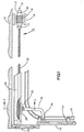
- FIG. 1 is a side elevational view, partly schematic, illustrating the invention.
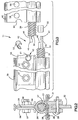
- FIG. 2 is an enlarged end sectional view taken along line 2--2 of FIG. 1.
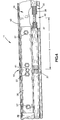
- FIG. 3 is an enlarged side elevational view of the door operator coupling assembly of FIG. 1 prior to assembly, to the same scale as FIG. 2.
- FIG. 4 is a side elevational view of the door operator coupling assembly of FIG. 3 after assembly.
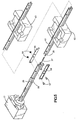
- FIG. 5 is a perspective view of the door operator showing the assembly of the coupling assembly.
- FIG. 6 is a graph showing the increase in ultimate yield torque achieved by the present invention.
- FIG. 7 is a graph showing the effect on ultimate tensile strength by the present invention.
- a garage door operator 10 which incorporates the screw and guide rail coupling assembly 11 of the present invention.
- the garage door operator 10 is intended to be installed within a garage having a ceiling 12 and a door header 13 .
- the operator 10 may open and close almost any type of closure device, including slab doors, which can be pivoted or operate on a form of a track.
- a sectional door 14 is illustrated which has sections hinged together and provided with rollers 15 to roll on a track 16 between the closed position shown and an open position near the ceiling 12 .
- the door operator 10 includes a motor 17 having a stator 18 and a rotor 19 , shown rather schematically in FIG. 1 .
- the motor 17 is connected to drive a screw 20 .
- the motor 17 has a shaft 21 connected to rotate the screw 20 , and this shaft 21 has bearings, including thrust bearings 22 , to absorb the longitudinal thrust in both directions on the screw 20 .
- the drive screw 20 is mounted at least partially within guide means comprising a guide rail 26 .
- the guide rail 26 has a generally cylindrical bore 27 , and the outer diameter of the drive screw 20 is only slightly smaller than the inner diameter of the cylindrical bore 27 , so that the screw fits closely within the guide rail.
- the cylindrical bore 27 circumscribes about 300° of the screw 20 .
- a partial nut 28 is disposed in the remaining 60° of the periphery of the screw 20 .
- the guide rail 26 provides guide means not only for the screw 20 , but also for the partial nut 28 .
- a slide 29 has wings 30 slidably disposed in grooves 31 in the guide rail 26 , and this slide 29 carries the partial nut 28 .
- a door arm 32 is pivotally connected at a connection point 33 to the slide 29 , and at a connection point 34 to the door 14 . Accordingly, as the motor 17 rotates the screw 20 in either a clockwise or counterclockwise direction, the partial nut 28 , engaged with the screw 20 , traverses the guide rail 26 longitudinally to open or close the garage door 14 .
- the screw 20 is formed in at least two screw parts 37 and 38
- the guide rail 26 is formed in at least two guide rail parts 39 and 40 . It has been found that a drive screw 20 formed in three parts with a guide rail formed in three parts is preferred. However, for the sake of clarity only two screw parts 37 and 38 and two guide rail parts 39 and 40 are illustrated in FIGS. 3 and 4 .
- the screw 20 and the guide rail 26 are formed in sectional parts, the overall length of the package in which the door operator is shipped is reduced.
- the length of the package can be reduced to approximately half if the screw and guide rail are in two parts, or can be reduced to approximately one-third if the screw and guide rail are in three parts.
- This reduction in package length not only saves shipping charges, but also saves storage charges, because door operators can be packed, shipped and stored in a much smaller volume of space.
- the reduction in space is of benefit to the distributor as well as the dealer. It is also of benefit to the ultimate customer because a package of nine to ten feet in length could not be brought home in the trunk of an automobile by an ordinary purchaser. If the length is reduced to 1 m (3 1 ⁇ 2) or 1,5 m (5 feet), however, such transport by the ultimate user is greatly facilitated.
- the first and second parts 37 and 38 , respectively, of the drive screw 20 and the first and second parts 39 and 40 , respectively, of the guide rail 26 are connected together by the coupling assembly 11 shown in more detail in FIGS. 3 and 4 .
- the coupling assembly 11 comprises a screw coupling 42 and a guide rail coupling 43 .
- the screw coupling 42 is fully described in U.S. Patent No. 4,352,585, the disclosure of which is incorporated by reference herein.
- the first and second screw coupling parts 45 and 46 are hermaphroditic parts wherein the first part 45 has a male shoulder 47 and a female groove 48 , and the second coupling part 46 has a male shoulder 49 and a female groove 50 .
- the screw coupling parts 45 and 46 when interengaged, form a reduced diameter portion of the screw 20 .
- the male shoulder 47 is extended from a reduced diameter portion 51 of the first screw part 37 .
- the portion 51 is reduced in diameter in order to accommodate the inside diameter of a sleeve 52 and also to accommodate the inside diameter of a C-clip 53 .
- the partial nut 28 has a length sufficient to bridge across the length of the screw coupling 42 , which is formed of the first and second screw coupling parts 45 and 46 , respectively.
- the screw coupling 42 has approximately the same external diameter as the screw 20 to permit the screw coupling to fit within the guide rail 26 and to permit the partial nut 28 to be in continuous engagement with the screw.
- the guide rail coupling 43 connects the two parts 39 and 40 of the guide rail 26 which are aligned after the screw coupling 42 is interconnected.
- the guide rail coupling 43 includes splice plates 56 , only one of which is shown in FIGS. 3 and 4 , one on each side of the guide rail 26 as shown in FIG. 2 , and fastened with bolts 57 extending through apertures 59 which engage corresponding nuts 58 to secure together the two parts of the guide rail in alignment.
- each part 39 and 40 of the guide rail 26 has a small semicircular recess 60 formed at the attachment end thereof.
- the center of each guide rail coupling 43 has a corresponding circular protrusion 61 extending toward the guide rail 26 .
- the circular protrusion 61 fits within the circular opening formed by the two semicircular recesses 60 to assist in positioning the guide rail coupling 43 on the guide rail 26 .
- the screw coupling 42 and the guide rail coupling 43 are longitudinally offset from each other, so that one of the guide rail parts 39 or 40 provides added support and alignment around the screw 20 at the location of the screw coupling 42 and one of the screw parts 37 or 38 provides support and alignment inside the guide rail 26 at the location of the guide rail coupling 43 .
- FIG. 6 shows the results of tests conducted on door operator assemblies according to the present invention in which the longitudinal position of the screw coupling 42 is offset from the longitudinal position of the guide rail coupling 43 .
- five door operator assemblies were tested at each of six offset distances x ranging from 2,54 cm (1 inch) to 15,24 cm (6 inches), a total of 30 door operator assemblies thus being tested.
- the door operator assemblies were of the common commercial type having screw parts and guide rail parts of about 0,9 m (3 feet) in length.
- the average ultimate yield torque for the five test samples at each offset distance is shown in FIG. 6 .
- the test results indicate that the ultimate torque increased generally linearly (with a correlation of 0.98) and a line showing this linearity is shown in FIG. 6 .
- the test results also indicated that a 15,24 cm (6-inch) offset produced the maximum increase in yield torque in a door operator of the conventional commercial type.
- the yield torque increased from approximately 17 Nm (151 inch-pounds) at zero offset to approximately 20 Nm (176 inch-pounds) at a 15,24 cm (6-inch) offset, resulting in about a 16% increase in ultimate yield torque.
- a 6-inch offset means that the screw part is about 15% longer than the guide rail
- a 5,08 cm (2-inch) offset means that the screw part is about 5% longer than the guide rail.
- the increase in torque strength is believed to occur because one of the guide rail parts 39 or 40 surrounds the screw coupling 42 and provides support and alignment on each side of the screw coupling, so that the screw parts 37 and 38 are maintained on the center line. By maintaining the screw parts 37 and 38 on the center line, there is less tendency for the screw parts to try to uncouple themselves.
- the screw parts were allowed greater movement because the screw coupling was positioned at the location of the guide rail coupling. The screw parts were thus allowed to "float" away from the center line and, under high torque loads, the screw parts tended to uncouple themselves, resulting in failure. This effect is avoided by the present invention.
- FIG. 7 shows the results of tests, similar to those conducted and shown in FIG. 6 , in which the ultimate tensile strength was measured for five door operator assemblies for each offset distance x from 2,54 cm (1 inch) to 15,24 cm (6 inches). The door operator assemblies were of the same common commercial type as those used in the tests shown in FIG. 6 . The average tensile strength for the five test samples at each offset distance is depicted in FIG. 7 . As shown in FIG. 7 , the ultimate tensile strength increased only about 3% from zero offset to an offset of 15,24 cm (6 inches).
- the coupling assembly of the prior art which provided no offset may provide sufficient tensile strength, due to the presence of the splice plates 56 , the interengaging portions of the screw coupling 42 and the sleeve 52 .
- An expected result of increasing tensile strength is not achieved by the present invention.
- torque strength is increased without increasing tensile strength, and this result is unexpected.
- the door operator 10 is shipped in a collapsed condition with the two (or more) screw parts 37 and 38 disposed side by side each within the respective guide rail parts 39 and 40 .
- One of the screw parts 37 or 38 may already be properly in working connection to the motor 17 , as illustrated by screw part 37 shown in FIG. 5 .
- the one end of the screw part 37 opposite the motor 17 preferably extends outwardly from the respective part 39 of the guide rail by the desired offset distance, approximately as shown in FIG. 5 , in accordance with this invention.
- the user or installer Upon unpacking, the user or installer first positions the guide rail parts 39 and 40 on a flat surface, generally as shown in FIG. 5 .
- Each of the screw parts 37 and 38 is preinstalled in the respective guide rail parts 39 and 40 .
- the screw part 38 is capable of longitudinal sliding movement and positioning within the guide rail part 40 prior to interconnection.
- the screw part 38 in the guide rail part 40 slides longitudinally toward the screw part 37 to position the screw parts 37 and 38 in an abutting
- the proper alignment of the guide rail parts 39 and 40 may be aided by the use of one or more support fixtures or jigs 63 .
- the support jigs 63 help to hold the guide rail parts 39 and 40 in proper alignment and also raise the second guide rail part 40 above the flat surface on which the assembly takes place to maintain the second guide rail part 40 in the same horizontal plane as the first guide rail part 39 which is elevated by reason of its attachment to the motor 17 .
- Each of the support jigs 63 may be provided to the user or installer in the form of foam packing blocks which would also be configured to fit around the motor 17 when the door operator assembly is packaged. The support jigs 63 or packing blocks would be removed from around the motor 17 when the door operator assembly is unpackaged and would be positioned so as to support the guide rail parts 39 and 40 in proper alignment.
- the screw coupling 42 is connected together as described in U.S. Patent No. 4,352,585.
- the sleeve 52 is first slipped over the male shoulder 49 onto the reduced diameter portion 51 .
- the two screw coupling parts 45 and 46 are then disposed side by side and axially parallel about as shown in FIG. 3.
- the guide rail parts 39 and 40 are moved to be coaxial to interengage the screw coupling 45 and 46 .
- the sleeve 52 slides to the right as viewed in FIG. 3 , and the C clip 53 is transversely inserted over the reduced diameter portion 51 . This prevents the sleeve 52 from moving to the left whereat it would not be covering the interengaged screw coupling parts 45 and 46 .
- the guide rail part 40 slides to the right (as shown in FIG. 5 ) while the screw part 38 remains stationary until the guide rail part 40 abuts the guide rail part 39 .
- the guide rail parts 39 and 40 are thus moved axially together, with the guide rail part 40 sliding over the screw 20 .
- the splice plates 56 are next positioned in place by locating the circular protrusion 61 on each splice plate into the circular hole formed by the semicircular recesses 60 on the end of each guide rail part 39 and 40 , and the splice plates 56 are bolted in place, using the bolts 57 and nuts 58 through the apertures 59 . Additional screw parts and guide rail parts, if any, are then added to the assembly in the same manner.
- the door operator 10 may then be installed against the ceiling 12 and door header 13 in the usual manner, and connected to the door 14 to move it between the open and closed positions.
Landscapes
- Power-Operated Mechanisms For Wings (AREA)
- Lock And Its Accessories (AREA)
- Gates (AREA)
Abstract
Description
- This invention relates to automatic door operators having a drive screw within a guide means, and more particularly to a coupling assembly for the drive screw and the guide means.
- Garage door operators have been manufactured and sold for over 40 years. The concept of a longitudinally stationary but rotating screw to act on a traveling nut to open an overhead-type garage door was shown to have been conceived over 45 years ago in U.S. Patent No. 2,056,174. Cable-operated or chain-operated garage door operators have also been proposed, for example, as shown by U.S. Patents Nos. 3,439,727 and 3,444,650. Typically, garage door operators provide a traverse of the door operator mechanism of about eight or nine feet in order to accommodate the usual height of the garage door plus the 90° angle through which the door turns.
- In the chain-type garage door operator that has been manufactured, it has been customary for many years to shorten the package in which the door operator is shipped by cutting the guide channel into two or three parts which may be spliced together. The channel which was previously nine feet long could comprise three parts of about three feet in length each. The screw drive door operators which were marketed at that time retained a one-piece screw and a one-piece guide means of about nine feet in length, which made the package costs higher and, more importantly, made the shipping and storage costs higher because the shipping charges are usually based upon the cubic volume of the package rather than upon the weight.
- Screw drive garage door operators have now been developed in which the guide means is in two or three parts and the screw is in two or three parts. Initially, the screw and the guide means were interconnected by coupling means which had an interconnecting link with a pivot pin at each end pivoted to the screw parts. In one early version of such an operator, the guide means and screw parts were folded for shipment and then, upon installation, where straightened to be coaxial, and splice plates were bolted onto the sides of the guide means to maintain the coaxial alignment of the screw parts. An example of this type of coupling assembly is shown in Patent No. 4,241,540, issued to Depperman.
- Some of the problems with this construction were the weakness of the screw coupling relative to the rest of the screw, the alignment of the guide means when it was properly straightened, and the whipping of the screw during rotation which, because of two different pivot points, acted somewhat like a universal joint to whip around inside the guide means. The coupling for the two screw parts also had so many different parts that the possible cumulative error in the tolerance of all these manufactured parts made it possible that the threads on the two screw parts could be mismatched relative to the traversing partial nut, and thus the nut would fail to traverse this elongated coupling. Also, the very many parts in this coupling and the necessary clearance between the parts to permit folding caused the coupling to tend to destroy itself upon repeated reversals of the screw.
- Many of these problems were overcome by the screw coupling disclosed in U.S. Patent No. 4,352,585, issued to Spalding. The preamble of
independent claims - The present invention provides an improved screw and guide means coupling assembly which overcomes the disadvantages and shortcomings of the prior art.
- Instead of locating the screw coupling and the guide means coupling at the same longitudinal position along the door operator, the present invention provides for offsetting the screw coupling and the guide means coupling so that they do not occur in the same longitudinal location. This eliminates the inherent weakness in the door operator assembly resulting from the combined effects of having the screw coupling and the guide means coupling in the same position. It also provides for aligning support for the screw and for the guide means so that misalignments are reduced and controlled.
- In accordance with the present invention, the screw coupling and the guide means coupling are longitudinally offset, so that one of the guide means parts provide added support and alignment around the screw at the position of the screw coupling and one of the screw parts provides support and alignment inside the guide means at the location of the guide means coupling.
- The screw and guide means coupling assembly of the present invention has been shown to provide a significant increase in the ultimate yield torque of the door operator assembly. When the screw coupling is offset longitudinally by a distance of 15,24 cm (6 inches) from the location of the guide means coupling, the ultimate yield torque can be increased as much as 16%. This increase in torque strength is believed to occur because the guide means surrounds the screw coupling and provides support and alignment to the screw parts on each side of the screw coupling, so that the screw parts are maintained on the center line. By coaxially maintaining the screw parts, there is less tendency for the screw parts to try to uncouple themselves. In the prior art door operator, the screw parts were allowed greater movement because they were positioned at the location of the guide means coupling. The screw parts were thus allowed to "float" off the center line and, under high torque loads, the screw parts tended to uncouple themselves, resulting in failure. This effect is avoided by the present invention.
- While the present invention results in a significant increase in ultimate yield torque, the accompanying increase in the ultimate tensile strength of the coupling is insignificant. The expected result of increasing tensile strength is not achieved by the present invention. However, the torque strength is increased even though tensile strength is not, achieving an unexpected result.
- These and other advantages are achieved by the appparatus of the present invention which is a garage door operator comprising a motor-driven rotatable screw at least partially within a nonrotatable guide rail, a means guided by the guide rail and movable longitudinally therealong by engagement with the screw and connectable to the garage door to open and close the latter, the screw constituted by at least first and second screw parts, a screw coupling adapted to interconnect adjacent ends of the at least first and second screw parts, the guide rail constituted by at least first and second guide rail parts, and a guide rail coupling adapted to interconnect the adjacent ends of the at least first and second guide parts, characterized in that the screw coupling is longitudinally spaced from the guide rail coupling, the screw coupling is completely contained and supported within one of said first and second guide rail parts without containment within the guide rail coupling.
- In accordance with the method of the present invention, there is a method of assembling a garage door operator having a motor-driven screw at least partially within a guide rail, the screw being in at least first and second screw parts, the guide rail being in at least first and second guide rail parts, the first screw part located within the first guide rail part to form a first partial assembly, the second screw part located within the second guide rail part to form a second partial assembly, the method comprising the steps of: positioning the second partial assembly in general coaxial alignment with the first partial assembly; interconnecting adjacent ends of the first and second screw parts using a screw coupling; and interconnecting adjacent ends of the first and second guide rail parts using a guide rail coupling; characterized in that the screw coupling is slided a substantial distance into the second guide rail part so that the screw coupling is longitudinally spaced from the guide rail coupling such that the screw coupling is completely contained and supported within the second guide rail part without containment within the guide rail coupling.
- Another method of assembling a garage door operator, which is also object of the present invention, is defined in
independent claim 13. - FIG. 1 is a side elevational view, partly schematic, illustrating the invention.
- FIG. 2 is an enlarged end sectional view taken along
line 2--2 of FIG. 1. - FIG. 3 is an enlarged side elevational view of the door operator coupling assembly of FIG. 1 prior to assembly, to the same scale as FIG. 2.
- FIG. 4 is a side elevational view of the door operator coupling assembly of FIG. 3 after assembly.
- FIG. 5 is a perspective view of the door operator showing the assembly of the coupling assembly.
- FIG. 6 is a graph showing the increase in ultimate yield torque achieved by the present invention.
- FIG. 7 is a graph showing the effect on ultimate tensile strength by the present invention.
- Referring more particularly to the drawings and initially to FIG. 1, there is shown a
garage door operator 10 which incorporates the screw and guiderail coupling assembly 11 of the present invention. Thegarage door operator 10 is intended to be installed within a garage having aceiling 12 and adoor header 13. Theoperator 10 may open and close almost any type of closure device, including slab doors, which can be pivoted or operate on a form of a track. However, asectional door 14 is illustrated which has sections hinged together and provided withrollers 15 to roll on atrack 16 between the closed position shown and an open position near theceiling 12. Thedoor operator 10 includes amotor 17 having astator 18 and arotor 19, shown rather schematically in FIG. 1. Themotor 17 is connected to drive ascrew 20. Themotor 17 has ashaft 21 connected to rotate thescrew 20, and thisshaft 21 has bearings, includingthrust bearings 22, to absorb the longitudinal thrust in both directions on thescrew 20. - As shown in FIG. 2, the
drive screw 20 is mounted at least partially within guide means comprising aguide rail 26. Theguide rail 26 has a generallycylindrical bore 27, and the outer diameter of thedrive screw 20 is only slightly smaller than the inner diameter of thecylindrical bore 27, so that the screw fits closely within the guide rail. Thecylindrical bore 27 circumscribes about 300° of thescrew 20. In the remaining 60° of the periphery of thescrew 20, apartial nut 28 is disposed. Theguide rail 26 provides guide means not only for thescrew 20, but also for thepartial nut 28. Aslide 29 haswings 30 slidably disposed ingrooves 31 in theguide rail 26, and thisslide 29 carries thepartial nut 28. Adoor arm 32 is pivotally connected at aconnection point 33 to theslide 29, and at aconnection point 34 to thedoor 14. Accordingly, as themotor 17 rotates thescrew 20 in either a clockwise or counterclockwise direction, thepartial nut 28, engaged with thescrew 20, traverses theguide rail 26 longitudinally to open or close thegarage door 14. - In the
garage door operator 10, thescrew 20 is formed in at least twoscrew parts guide rail 26 is formed in at least twoguide rail parts drive screw 20 formed in three parts with a guide rail formed in three parts is preferred. However, for the sake of clarity only twoscrew parts guide rail parts screw 20 and theguide rail 26 in sectional parts, the overall length of the package in which the door operator is shipped is reduced. Since the shipping costs are based primarily on the cubic volume rather than the weight, the length of the package can be reduced to approximately half if the screw and guide rail are in two parts, or can be reduced to approximately one-third if the screw and guide rail are in three parts. This reduction in package length not only saves shipping charges, but also saves storage charges, because door operators can be packed, shipped and stored in a much smaller volume of space. The reduction in space is of benefit to the distributor as well as the dealer. It is also of benefit to the ultimate customer because a package of nine to ten feet in length could not be brought home in the trunk of an automobile by an ordinary purchaser. If the length is reduced to 1 m (3 ½) or 1,5 m (5 feet), however, such transport by the ultimate user is greatly facilitated. - The first and
second parts drive screw 20 and the first andsecond parts guide rail 26 are connected together by thecoupling assembly 11 shown in more detail in FIGS. 3 and 4. Thecoupling assembly 11 comprises ascrew coupling 42 and aguide rail coupling 43. - The
screw coupling 42 is fully described in U.S. Patent No. 4,352,585, the disclosure of which is incorporated by reference herein. As shown in FIG. 3, the first and secondscrew coupling parts first part 45 has amale shoulder 47 and afemale groove 48, and thesecond coupling part 46 has amale shoulder 49 and afemale groove 50. Thescrew coupling parts screw 20. Themale shoulder 47 is extended from a reduceddiameter portion 51 of thefirst screw part 37. Theportion 51 is reduced in diameter in order to accommodate the inside diameter of asleeve 52 and also to accommodate the inside diameter of a C-clip 53. Thepartial nut 28 has a length sufficient to bridge across the length of thescrew coupling 42, which is formed of the first and secondscrew coupling parts screw coupling 42 has approximately the same external diameter as thescrew 20 to permit the screw coupling to fit within theguide rail 26 and to permit thepartial nut 28 to be in continuous engagement with the screw. - As shown in FIGS. 3 and 4, the
guide rail coupling 43 connects the twoparts guide rail 26 which are aligned after thescrew coupling 42 is interconnected. Theguide rail coupling 43 includessplice plates 56, only one of which is shown in FIGS. 3 and 4, one on each side of theguide rail 26 as shown in FIG. 2, and fastened withbolts 57 extending throughapertures 59 which engage correspondingnuts 58 to secure together the two parts of the guide rail in alignment. Preferably, eachpart guide rail 26 has a smallsemicircular recess 60 formed at the attachment end thereof. The center of eachguide rail coupling 43 has a correspondingcircular protrusion 61 extending toward theguide rail 26. Thecircular protrusion 61 fits within the circular opening formed by the twosemicircular recesses 60 to assist in positioning theguide rail coupling 43 on theguide rail 26. - In prior art coupling assemblies, such as that shown in Patent No. 4,352,585, the screw coupling and the guide rail coupling were both located in the same position along the length of the door operator. This resulted in an inherent weakness at the position of the coupling assembly. In accordance with the present invention, the
screw coupling 42 and theguide rail coupling 43 are longitudinally offset from each other, so that one of theguide rail parts screw 20 at the location of thescrew coupling 42 and one of thescrew parts guide rail 26 at the location of theguide rail coupling 43. - As shown more particularly in FIG. 4, the longitudinal position of
screw coupling 42 is spaced by a distance of x from the longitudinal position of theguide rail coupling 43. This longitudinal spacing has the effect of strengthening the screw drive assembly and maintaining the drive screw in proper alignment at the location of the screw coupling. This result can be seen with reference to FIG. 6 which shows the results of tests conducted on door operator assemblies according to the present invention in which the longitudinal position of thescrew coupling 42 is offset from the longitudinal position of theguide rail coupling 43. In the tests depicted in FIG. 6, five door operator assemblies were tested at each of six offset distances x ranging from 2,54 cm (1 inch) to 15,24 cm (6 inches), a total of 30 door operator assemblies thus being tested. The door operator assemblies were of the common commercial type having screw parts and guide rail parts of about 0,9 m (3 feet) in length. The average ultimate yield torque for the five test samples at each offset distance is shown in FIG. 6. The test results indicate that the ultimate torque increased generally linearly (with a correlation of 0.98) and a line showing this linearity is shown in FIG. 6. The test results also indicated that a 15,24 cm (6-inch) offset produced the maximum increase in yield torque in a door operator of the conventional commercial type. The yield torque increased from approximately 17 Nm (151 inch-pounds) at zero offset to approximately 20 Nm (176 inch-pounds) at a 15,24 cm (6-inch) offset, resulting in about a 16% increase in ultimate yield torque. A significant increase in yield torque of 7% was achieved with only a 5,08 cm (2-inch) offset, so that at least some of the advantage of the present invention can be achieved with an offset of only 5,08 cm (2 inches). However, the preferred offset is 15,24 cm (6 inches), since this produced the maximum increase in yield torque. - Using door operator assemblies of the common commercial type in which a guide rail part is approximately 0,9 m (3 feet) long, a 6-inch offset means that the screw part is about 15% longer than the guide rail, and a 5,08 cm (2-inch) offset means that the screw part is about 5% longer than the guide rail.
- The increase in torque strength is believed to occur because one of the
guide rail parts screw coupling 42 and provides support and alignment on each side of the screw coupling, so that thescrew parts screw parts - While the present invention results in a significant increase in ultimate yield torque, there is no significant increase in the ultimate tensile strength of the coupling. FIG. 7 shows the results of tests, similar to those conducted and shown in FIG. 6, in which the ultimate tensile strength was measured for five door operator assemblies for each offset distance x from 2,54 cm (1 inch) to 15,24 cm (6 inches). The door operator assemblies were of the same common commercial type as those used in the tests shown in FIG. 6. The average tensile strength for the five test samples at each offset distance is depicted in FIG. 7. As shown in FIG. 7, the ultimate tensile strength increased only about 3% from zero offset to an offset of 15,24 cm (6 inches). Thus, the coupling assembly of the prior art which provided no offset may provide sufficient tensile strength, due to the presence of the
splice plates 56, the interengaging portions of thescrew coupling 42 and thesleeve 52. An expected result of increasing tensile strength is not achieved by the present invention. However, torque strength is increased without increasing tensile strength, and this result is unexpected. - The assembly and operation of the
door operator 10 of the present invention can be understood with reference to FIGS. 3, 4 and 5. - The
door operator 10 is shipped in a collapsed condition with the two (or more) screwparts guide rail parts screw parts motor 17, as illustrated byscrew part 37 shown in FIG. 5. As shipped, the one end of thescrew part 37 opposite themotor 17 preferably extends outwardly from therespective part 39 of the guide rail by the desired offset distance, approximately as shown in FIG. 5, in accordance with this invention. Upon unpacking, the user or installer first positions theguide rail parts screw parts guide rail parts screw part 38 is capable of longitudinal sliding movement and positioning within theguide rail part 40 prior to interconnection. Thescrew part 38 in theguide rail part 40 slides longitudinally toward thescrew part 37 to position thescrew parts - The proper alignment of the
guide rail parts guide rail parts guide rail part 40 above the flat surface on which the assembly takes place to maintain the secondguide rail part 40 in the same horizontal plane as the firstguide rail part 39 which is elevated by reason of its attachment to themotor 17. Each of the support jigs 63 may be provided to the user or installer in the form of foam packing blocks which would also be configured to fit around themotor 17 when the door operator assembly is packaged. The support jigs 63 or packing blocks would be removed from around themotor 17 when the door operator assembly is unpackaged and would be positioned so as to support theguide rail parts - With the
screw parts screw coupling 42 is connected together as described in U.S. Patent No. 4,352,585. Thesleeve 52 is first slipped over themale shoulder 49 onto the reduceddiameter portion 51. The twoscrew coupling parts guide rail parts screw coupling sleeve 52 slides to the right as viewed in FIG. 3, and theC clip 53 is transversely inserted over the reduceddiameter portion 51. This prevents thesleeve 52 from moving to the left whereat it would not be covering the interengagedscrew coupling parts screw part 37 in operative connection with themotor 17, theguide rail part 40 slides to the right (as shown in FIG. 5) while thescrew part 38 remains stationary until theguide rail part 40 abuts theguide rail part 39. Theguide rail parts guide rail part 40 sliding over thescrew 20. Thesplice plates 56 are next positioned in place by locating thecircular protrusion 61 on each splice plate into the circular hole formed by thesemicircular recesses 60 on the end of eachguide rail part splice plates 56 are bolted in place, using thebolts 57 andnuts 58 through theapertures 59. Additional screw parts and guide rail parts, if any, are then added to the assembly in the same manner. Thedoor operator 10 may then be installed against theceiling 12 anddoor header 13 in the usual manner, and connected to thedoor 14 to move it between the open and closed positions. - It is not possible to connect the
screw coupling 42 so that the twoscrew parts partial nut 28, which traverses the coupling for each door opening or closing movement. Because thescrew coupling 42 is a hermaphroditic coupling, i.e., one which has partly male and partly female properties, it is impossible to connect the screw coupling in other than the correct manner. The coupling part interconnection also minimizes the possible cumulative tolerance errors as more fully described in U.S. Patent No. 4,352,585. - While the invention has been shown and described with respect to a particular embodiment thereof, this is for the purpose of illustration rather than limitation, and other variations and modifications of the specific embodiment herein shown and described will be apparent to those skilled in the art all within the intended spirit and scope of the invention.
Claims (15)
- A garage door operator (10), comprising:a motor-driven rotatable screw (20) at least partially within a nonrotatable guide rail (26),a means (29) guided by the guide rail (26) and movable longitudinally therealong by engagement with the screw (20) and connectable to the garage door (14) to open and close the latter,the screw (20) being constituted by at least first and second screw parts (37, 38),a screw coupling (42) adapted to interconnect adjacent ends of the at least first and second screw parts (37, 38),the guide rail (26) being constituted by at least first and second guide rail parts (39, 40), anda guide rail coupling (43) adapted to interconnect the adjacent ends of the at least first and second guide rail parts (39, 40),characterized in that
the screw coupling (42) is longitudinally spaced from the guide rail coupling (43), the screw coupling (42) is completely contained and supported within one of said first and second guide rail parts (39, 40) without containment within the guide rail coupling (43). - The garage door operator (10) of claim 1, wherein the first screw part (37) is substantially longer than the corresponding first guide rail part (39), and the first screw part extends a substantial distance into the second guide rail part (40).
- The garage door operator (10) of claim 1, wherein the first screw part (37) is at least 10% longer than the corresponding first guide rail part (39).
- The garage door operator (10) of claim 1, wherein the screw coupling (42) is longitudinally spaced at least 5,08 cm (two inches) from the guide rail coupling (43).
- The garage door operator (10) of claim 1, wherein the screw coupling (42) is longitudinally, spaced at least approximately 15,24 cm (six inches) from the guide rail coupling (43).
- The garage door operator (10) of claim 1, wherein the screw coupling (42) comprises means for transmitting torque from the first screw part (37) to the second screw part (38).
- The garage door operator (10) of claim 1, wherein the screw (20) fits closely within a corresponding bore in the guide rail (26).
- The garage door operator (10) of claim 1, wherein the screw parts (37, 38) are capable of longitudinal sliding movement and positioning within the guide rail parts (39, 40) prior to interconnection.
- The garage door operator (10) of claim 1, wherein the screw coupling (42) has approximately the same external diameter as the screw parts (37, 38) to permit the screw coupling (42) to fit within the guide rail (26) and to permit the means movable longitudinally along the guide rail (26) to be in continuous engagement with the screw (20).
- A method of assembling a garage door operator (10) having a motor-driven screw (20) at least partially within a guide rail (26), the screw (20) being in at least first and second screw parts (37, 38), the guide rail (26) being in at least first and second guide rail parts (39, 40), the first screw part (37) located within the first guide rail part (39) to form a first partial assembly, the second screw part (38) located within the second guide rail part (40) to form a second partial assembly, the method comprising the steps of:positioning the second partial assembly in general coaxial alignment with the first partial assembly;interconnecting adjacent ends of the first and second screw parts (37, 38) using a screw coupling (42); andinterconnecting adjacent ends of the first and second guide rail parts (39, 40) using a guide rail coupling (43);characterized in that
the screw coupling (42) is slided a substantial distance into the second guide rail part (40) so that the screw coupling (42) is longitudinally spaced from the guide rail coupling (42) such that the screw coupling (42) is completely contained and supported within the second guide rail part (40), without containment within the guide rail coupling (43). - A method of assembling a garage door operator (10) as in claim 10, wherein the second partial assembly is positioned in general coaxial alignment with the first partial assembly using one or more support jigs (63) to elevate the second partial assembly and to hold the partial assemblies in an aligned position, and the adjacent ends of the first and second screw parts (37, 38) are interconnected while the screw parts (37, 38) are maintained in aligned position by the support jig (63).
- A method of assembling a garage door operator (10) as in claim 11, comprising the additional step of unpacking the motor and the partial assemblies from packing material before positioning the second partial assembly in general coaxial alignment with the first partial assembly, and using part of the packing material for the support jig (63).
- A method of assembling a garage door operator (10) having a motor-driven screw (20) at least partially within guide rail (26), the screw (20) being in at least first and second screw parts (37, 38), the guide rail (26) being in at least first and second guide rail parts (39, 40), the first screw part (37) located within the first guide rail part (39) to form a first partial assembly, the second screw part (38) located within the second guide rail part (40) to form a second partial assembly, the first partial assembly being connected to a motor, the method comprising the steps of:placing the partial assemblies on a flat surface;positioning the second partial assembly in general coaxial alignment with the first partial assembly usingone or more support jigs (63) comprising packing material for the door operator (10) being placed on the flat surface to elevate the second partial assembly above the flat surface and to hold the partial assemblies in an aligned position;the screw parts (37, 38) are maintained in aligned position by the one or more support jigs (63) while the adjacent ends of the first and second screw parts (37, 38) are interconnected using a screw coupling (42); andthe guide rail parts (39, 40) are maintained in aligned position by the one or more support jigs (63) while the adjacent ends of the first and second guide rail parts (39, 40) are interconnected using a guide rail coupling (43).
- A method of assembling a garage door operator (10) as in claim 13, comprising the additional step of unpacking the motor and the partial assemblies from packing material before placing the partial assemblies on a flat surface, and using a portion of the packing material for the support jig (63).
- A method of assembling a garage door operator (10) as in claim 13, comprising the additional step of sliding the screw coupling (42) a substantial distance into the second guide rail part (40) so that the screw coupling (42) is completely contained within the second guide rail part (40) after interconnecting adjacent ends of the first and second screw parts (37 38) using the screw coupling (42) and before interconnecting adjacent ends of the first and second guide rail parts (39, 40) using the guide rail coupling (43).
Applications Claiming Priority (2)
| Application Number | Priority Date | Filing Date | Title |
|---|---|---|---|
| US07/610,523 US5085094A (en) | 1990-11-08 | 1990-11-08 | Door operator coupling assembly |
| US610523 | 1990-11-08 |
Publications (2)
| Publication Number | Publication Date |
|---|---|
| EP0485294A1 EP0485294A1 (en) | 1992-05-13 |
| EP0485294B1 true EP0485294B1 (en) | 1996-08-14 |
Family
ID=24445362
Family Applications (1)
| Application Number | Title | Priority Date | Filing Date |
|---|---|---|---|
| EP91402996A Expired - Lifetime EP0485294B1 (en) | 1990-11-08 | 1991-11-07 | Door operator coupling assembly |
Country Status (6)
| Country | Link |
|---|---|
| US (1) | US5085094A (en) |
| EP (1) | EP0485294B1 (en) |
| JP (1) | JP3378024B2 (en) |
| AT (1) | ATE141381T1 (en) |
| CA (1) | CA2054500C (en) |
| DE (1) | DE69121358T2 (en) |
Families Citing this family (28)
| Publication number | Priority date | Publication date | Assignee | Title |
|---|---|---|---|---|
| FR2688020B1 (en) * | 1992-02-28 | 1997-04-11 | Rene Ruchat | DEVICE CONTROLLING THE OPENING AND CLOSING OF A HORIZONTALLY SLIDING DOOR IN A VEHICLE. |
| JPH06170676A (en) * | 1992-12-04 | 1994-06-21 | Toshiba Mach Co Ltd | Shaft rotation driving gear for machine tool |
| US5588257A (en) * | 1994-08-24 | 1996-12-31 | The Stanley Works | Garage door operator |
| US5568704A (en) * | 1995-03-24 | 1996-10-29 | Gmi Holdings, Inc. | Clutchless screw drive door operator |
| US5852949A (en) * | 1996-07-30 | 1998-12-29 | Thermo Fibertek Inc. | Segmented screw traversing mechanism |
| US6134838A (en) * | 1997-02-24 | 2000-10-24 | Westinghouse Air Brake Company | Power door having a drive member disposed within a hanger portion and rollers of a door support engaging the hanger portion for motion therealong |
| DE29720447U1 (en) * | 1997-11-18 | 1998-04-02 | MARANTEC Antriebs- und Steuerungstechnik GmbH & Co. Produktions-KG, 33428 Marienfeld | Drive spindle |
| US6588156B2 (en) | 2000-02-07 | 2003-07-08 | Wayne-Dalton Corp. | Sectional door operator alignment method |
| EP1128016B1 (en) * | 2000-02-21 | 2011-11-23 | Hörmann KG Antriebstechnik | Drive for a movable building closure, belt transmission and guide rail for use therein and method of assembing the same |
| DE10038077C2 (en) * | 2000-02-21 | 2003-02-20 | Hoermann Kg Antriebstechnik | Drive for a movable building closure, traction mechanism and guide rail for use therein and method for mounting the same |
| JP2002220179A (en) * | 2000-12-22 | 2002-08-06 | Inventio Ag | Door suspension system |
| US6753668B1 (en) * | 2002-05-31 | 2004-06-22 | Linear Corporation | Reduced profile drive assembly for garage door operator and method of assembly |
| WO2005045169A1 (en) * | 2003-10-17 | 2005-05-19 | Sanwa Shutter Corporation | Opening/closing device for building |
| JP2005195159A (en) * | 2004-01-09 | 2005-07-21 | Nsk Ltd | Ball screw device |
| US20060237150A1 (en) * | 2005-04-21 | 2006-10-26 | The Chamberlain Group, Inc. | Shaft coupling for barrier movement operators |
| US8001725B2 (en) * | 2005-09-30 | 2011-08-23 | The Chamberlain Group, Inc. | Shaft joint |
| US20080047672A1 (en) * | 2006-08-25 | 2008-02-28 | James Gorman | Garage door opener |
| CN101668714A (en) * | 2007-04-09 | 2010-03-10 | Lg化学株式会社 | multi-layered photochromic sheet and photochromic glass prepared therefrom |
| AU2008314516B2 (en) * | 2007-10-19 | 2014-01-30 | Automatic Technology (Australia) Pty Ltd | Improvements relating to drive assemblies |
| RU2364696C1 (en) | 2008-05-27 | 2009-08-20 | Общество с ограниченной ответственностью "ДорХан" | Sectional gates |
| JP6099156B2 (en) | 2011-05-24 | 2017-03-22 | オーバーヘッド ドア コーポレーション | Barrier operator system and method of operation |
| ITTV20120107A1 (en) * | 2012-06-04 | 2013-12-05 | Nice Spa | ELECTROMECHANICAL OPERATION FOR GARAGE DOOR |
| US20190195285A1 (en) * | 2016-08-03 | 2019-06-27 | Azbil Corporation | Transfer apparatus |
| US11256264B2 (en) | 2017-08-30 | 2022-02-22 | Assa Abloy Entrance Systems Ab | Vehicle guidance systems and associated methods of use at logistics yards and other locations |
| US11262747B2 (en) | 2019-06-11 | 2022-03-01 | Assa Abloy Entrance Systems Ab | Vehicle identification and guidance systems and associated methods |
| US12570129B2 (en) | 2021-06-02 | 2026-03-10 | Assa Abloy Entrance Systems Ab | Loading dock automated trailer door systems |
| WO2023274744A2 (en) | 2021-07-02 | 2023-01-05 | Assa Abloy Entrance Systems Ab | Powered trailer systems |
| US12400175B2 (en) | 2021-11-30 | 2025-08-26 | Assa Abloy Entrance Systems Ab | Trailer validation systems |
Family Cites Families (11)
| Publication number | Priority date | Publication date | Assignee | Title |
|---|---|---|---|---|
| US2056174A (en) * | 1934-11-13 | 1936-10-06 | John A Earhuff | Automatic closure operating device |
| US3290849A (en) * | 1964-09-02 | 1966-12-13 | Universal Building Products Co | Block with spacing legs and facing section |
| US3439727A (en) * | 1966-10-27 | 1969-04-22 | Tappan Co The | Garage door operator |
| US3444650A (en) * | 1967-05-05 | 1969-05-20 | Henry K Flinchbaugh | Apparatus for operating an overhead vehicle door |
| US3505831A (en) * | 1968-07-05 | 1970-04-14 | Skil Corp | Flexible shaft coupler |
| JPS562405U (en) * | 1979-06-20 | 1981-01-10 | ||
| US4241540A (en) * | 1979-07-18 | 1980-12-30 | Chamberlain Manufacturing Corporation | Folding screw and rail assembly for a garage door opener |
| US4352585A (en) * | 1980-03-06 | 1982-10-05 | The Alliance Manufacturing Company, Inc. | Door operator screw coupling |
| JPS6173572U (en) * | 1984-10-16 | 1986-05-19 | ||
| US4649016A (en) * | 1985-10-09 | 1987-03-10 | Westinghouse Electric Corp. | Remotely operable fuel transfer system for nuclear reactor |
| JPH0658017B2 (en) * | 1986-05-13 | 1994-08-03 | 富士変速機株式会社 | Guide rail connector |
-
1990
- 1990-11-08 US US07/610,523 patent/US5085094A/en not_active Expired - Lifetime
-
1991
- 1991-10-30 CA CA002054500A patent/CA2054500C/en not_active Expired - Lifetime
- 1991-11-07 JP JP29142591A patent/JP3378024B2/en not_active Expired - Lifetime
- 1991-11-07 DE DE69121358T patent/DE69121358T2/en not_active Expired - Lifetime
- 1991-11-07 EP EP91402996A patent/EP0485294B1/en not_active Expired - Lifetime
- 1991-11-07 AT AT91402996T patent/ATE141381T1/en not_active IP Right Cessation
Also Published As
| Publication number | Publication date |
|---|---|
| JPH04265388A (en) | 1992-09-21 |
| US5085094A (en) | 1992-02-04 |
| CA2054500A1 (en) | 1992-05-09 |
| EP0485294A1 (en) | 1992-05-13 |
| CA2054500C (en) | 1995-06-20 |
| ATE141381T1 (en) | 1996-08-15 |
| DE69121358D1 (en) | 1996-09-19 |
| DE69121358T2 (en) | 1996-12-12 |
| JP3378024B2 (en) | 2003-02-17 |
Similar Documents
| Publication | Publication Date | Title |
|---|---|---|
| US5085094A (en) | Door operator coupling assembly | |
| US4352585A (en) | Door operator screw coupling | |
| CA1125800A (en) | Folding screw and rail assembly for a garage door opener | |
| US5054550A (en) | Centering spinning for down hole tubulars | |
| JP5937010B2 (en) | Guide structure with transport mechanism | |
| US20080047672A1 (en) | Garage door opener | |
| US6742303B2 (en) | Linear actuator for gates, doors and the like | |
| CA1307098C (en) | System for assembling bottom parts for vehicles | |
| EP1767721B1 (en) | Awning arm support with adjustable angle of inclination | |
| US8001725B2 (en) | Shaft joint | |
| US11053756B2 (en) | Torque-dependent oscillation of a dual-pipe inner pipe section | |
| CA2544088A1 (en) | Shaft coupling for barrier movement operators | |
| US4619159A (en) | Wrenching unit for use in power threading of a sleeve portion to a pipe portion used in makeup of oil well casings or the like | |
| US6606760B1 (en) | Vehicle wiper device with installation positioning mechanism | |
| EP3992054B1 (en) | Foldable vehicular coupler and vehicle | |
| JPH06508896A (en) | Electric actuators for doors and windows | |
| JP4742086B2 (en) | Watertight structure of track rail | |
| JP4351612B2 (en) | Screw member tightening device | |
| JP4742085B2 (en) | Hinge type waterproof gate | |
| JP2006142415A (en) | Screw member supply tightening device | |
| US20260048490A1 (en) | Torsion spring tensioning tool | |
| JP2009084883A (en) | Watertight gate for railroad track | |
| EP1167672B1 (en) | Open-close device for embeddable sliding doors | |
| CN111196283B (en) | Locking mechanism of piggyback vehicle and supporting part | |
| JPH0322986B2 (en) |
Legal Events
| Date | Code | Title | Description |
|---|---|---|---|
| PUAI | Public reference made under article 153(3) epc to a published international application that has entered the european phase |
Free format text: ORIGINAL CODE: 0009012 |
|
| AK | Designated contracting states |
Kind code of ref document: A1 Designated state(s): AT DE FR GB IT |
|
| 17P | Request for examination filed |
Effective date: 19921015 |
|
| 17Q | First examination report despatched |
Effective date: 19940826 |
|
| GRAH | Despatch of communication of intention to grant a patent |
Free format text: ORIGINAL CODE: EPIDOS IGRA |
|
| GRAA | (expected) grant |
Free format text: ORIGINAL CODE: 0009210 |
|
| AK | Designated contracting states |
Kind code of ref document: B1 Designated state(s): AT DE FR GB IT |
|
| REF | Corresponds to: |
Ref document number: 141381 Country of ref document: AT Date of ref document: 19960815 Kind code of ref document: T |
|
| ITF | It: translation for a ep patent filed | ||
| REF | Corresponds to: |
Ref document number: 69121358 Country of ref document: DE Date of ref document: 19960919 |
|
| ET | Fr: translation filed | ||
| PLBE | No opposition filed within time limit |
Free format text: ORIGINAL CODE: 0009261 |
|
| STAA | Information on the status of an ep patent application or granted ep patent |
Free format text: STATUS: NO OPPOSITION FILED WITHIN TIME LIMIT |
|
| 26N | No opposition filed | ||
| REG | Reference to a national code |
Ref country code: GB Ref legal event code: IF02 |
|
| PGFP | Annual fee paid to national office [announced via postgrant information from national office to epo] |
Ref country code: AT Payment date: 20021114 Year of fee payment: 12 |
|
| PG25 | Lapsed in a contracting state [announced via postgrant information from national office to epo] |
Ref country code: AT Free format text: LAPSE BECAUSE OF NON-PAYMENT OF DUE FEES Effective date: 20031107 |
|
| PGFP | Annual fee paid to national office [announced via postgrant information from national office to epo] |
Ref country code: IT Payment date: 20071119 Year of fee payment: 17 |
|
| PGFP | Annual fee paid to national office [announced via postgrant information from national office to epo] |
Ref country code: FR Payment date: 20071126 Year of fee payment: 17 Ref country code: GB Payment date: 20071107 Year of fee payment: 17 |
|
| GBPC | Gb: european patent ceased through non-payment of renewal fee |
Effective date: 20081107 |
|
| PG25 | Lapsed in a contracting state [announced via postgrant information from national office to epo] |
Ref country code: IT Free format text: LAPSE BECAUSE OF NON-PAYMENT OF DUE FEES Effective date: 20081107 |
|
| REG | Reference to a national code |
Ref country code: FR Ref legal event code: ST Effective date: 20090731 |
|
| PG25 | Lapsed in a contracting state [announced via postgrant information from national office to epo] |
Ref country code: GB Free format text: LAPSE BECAUSE OF NON-PAYMENT OF DUE FEES Effective date: 20081107 |
|
| PGFP | Annual fee paid to national office [announced via postgrant information from national office to epo] |
Ref country code: DE Payment date: 20100127 Year of fee payment: 19 |
|
| REG | Reference to a national code |
Ref country code: DE Ref legal event code: R119 Ref document number: 69121358 Country of ref document: DE Effective date: 20110601 Ref country code: DE Ref legal event code: R119 Ref document number: 69121358 Country of ref document: DE Effective date: 20110531 |
|
| PG25 | Lapsed in a contracting state [announced via postgrant information from national office to epo] |
Ref country code: DE Free format text: LAPSE BECAUSE OF NON-PAYMENT OF DUE FEES Effective date: 20110531 Ref country code: FR Free format text: LAPSE BECAUSE OF NON-PAYMENT OF DUE FEES Effective date: 20081130 |