EP0485268B1 - Matrix screen image projector with two polarized beams - Google Patents
Matrix screen image projector with two polarized beams Download PDFInfo
- Publication number
- EP0485268B1 EP0485268B1 EP91402942A EP91402942A EP0485268B1 EP 0485268 B1 EP0485268 B1 EP 0485268B1 EP 91402942 A EP91402942 A EP 91402942A EP 91402942 A EP91402942 A EP 91402942A EP 0485268 B1 EP0485268 B1 EP 0485268B1
- Authority
- EP
- European Patent Office
- Prior art keywords
- image projector
- matrix screen
- projector according
- beams
- polarized
- Prior art date
- Legal status (The legal status is an assumption and is not a legal conclusion. Google has not performed a legal analysis and makes no representation as to the accuracy of the status listed.)
- Expired - Lifetime
Links
Images


Classifications
-
- H—ELECTRICITY
- H04—ELECTRIC COMMUNICATION TECHNIQUE
- H04N—PICTORIAL COMMUNICATION, e.g. TELEVISION
- H04N9/00—Details of colour television systems
- H04N9/12—Picture reproducers
- H04N9/31—Projection devices for colour picture display, e.g. using electronic spatial light modulators [ESLM]
- H04N9/3141—Constructional details thereof
- H04N9/315—Modulator illumination systems
- H04N9/3167—Modulator illumination systems for polarizing the light beam
-
- H—ELECTRICITY
- H04—ELECTRIC COMMUNICATION TECHNIQUE
- H04N—PICTORIAL COMMUNICATION, e.g. TELEVISION
- H04N5/00—Details of television systems
- H04N5/74—Projection arrangements for image reproduction, e.g. using eidophor
- H04N5/7416—Projection arrangements for image reproduction, e.g. using eidophor involving the use of a spatial light modulator, e.g. a light valve, controlled by a video signal
- H04N5/7441—Projection arrangements for image reproduction, e.g. using eidophor involving the use of a spatial light modulator, e.g. a light valve, controlled by a video signal the modulator being an array of liquid crystal cells
Definitions
- the invention relates to image projectors in which spatial modulation of light is carried out using a liquid crystal screen.
- It relates more particularly to image projectors using the two orthogonal and complementary directions of polarization of light.
- the image projected on a screen results from a spatial modulation of light.
- the light produced by a source is guided to a light modulation assembly grouping together the means necessary to achieve the spatial modulation of the light.
- a spatial light modulator a liquid crystal screen (abbreviated as "LCD matrix screen” from the English “Liquid Crystal Display”) comprising a matrix array of elementary liquid crystal cells, controlled from a video signal; each cell representing an elementary image point.
- the simplest way to form an image using an LCD matrix screen is to illuminate it with linearly polarized light.
- polarization analyzer a second polarizer
- the structure described in the above-mentioned document has at least one significant drawback, which resides in the fact that it leads, either to a relatively large size of the projector, (distance between the polarization splitter element and the matrix screen LCD) to prevent the two beams propagating towards the LCD matrix screen by forming a relatively large angle between them; or the obligation to use a projection lens with large aperture.
- Another drawback of this structure is that it does not allow symmetrical optical paths to be given to the two polarized beams, so that it is difficult to perfectly superimpose on the same screen.
- LCD matrix the lighting tasks formed by these two beams, that is to say superimposing the sections of these two beams.
- the present invention relates to an image projector of the type in which the illumination of the LCD matrix screen is produced by two polarized beams, after rotation of 90 ° in the direction of polarization of one of these two beams.
- the invention proposes a new arrangement of such a modulation assembly, an arrangement which in particular makes it possible to confer a small bulk to the modulation assembly, while allowing the use of a projection objective having a small aperture.
- the invention applies equally to image projectors of the so-called “frontal” type (diffusing reflection of the light projected on the projection screen), as of the so-called “rear” type (diffusing transmission of the light projected on the projection screen).
- the invention also applies equally well to producing monochrome images as color images.
- an image projector comprising at least one liquid crystal matrix screen, at least one polarization direction rotator element, at least one polarization splitter separating the light into two polarized beams having one with respect to the other of the orthogonal polarization directions, the two polarized beams being intended to be modulated by the matrix screen after one of these beams has passed through the rotator element, is characterized in that it comprises, part of the first means for carrying out at least two reflections for each polarized beam, a first reflection reflecting the beam towards an optical axis on which the matrix screen is centered, and a second reflection then reflecting it towards the screen matrix, and in that it also comprises second means for making each polarized beam converge on at least part of its path between the polarization splitter and the matrix screen, so that each polarized beam forms an image of the light source between the first reflection and the matrix screen.
- This arrangement makes it possible in particular to orient the two polarized beams in the direction of the matrix screen, by mirrors situated very close to the main optical axis, so that the two polarized beams form a small angle between them, and that each polarized beam forms an image of the light source near the optical axis.
- This arrangement also offers the advantage of allowing perfect symmetry in the paths of the two polarized beams.
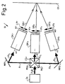
- FIG. 1 shows the diagram of an image projector 1 according to the invention, of the monochrome type.
- the projector 1 comprises a light source 2 producing a beam FS of light called the source beam, of which the light does not have a particular direction of polarization.
- the rays of the source beam are practically parallel.
- the light source can be constituted by a lighting lamp (not shown) placed at the focus of a parabolic reflector (not shown), or even at the focus of a converging lens.
- the source beam FS propagates along a propagation axis x1, in the direction of a polarization splitter SP.
- the polarization splitter SP can be of a conventional type; it can be constituted for example by a polarization separating surface SP formed by a stack of films in thin layers of dielectric materials, so as to alternate different refractive indices according to a conventional technique. There are commonly found in the trade such polarization separating surfaces produced in cubes called "polarization separator cubes".
- the separating surface SP is located on the propagation axis x1 and forms with the latter an angle a1 of 45 °.
- the separating surface SP decomposes the source beam FS into two polarized beams FP1, FP2 of practically equal intensity, but whose polarization directions are perpendicular.
- the first polarized beam FP1 is a transmitted beam which, having crossed the separating surface SP, propagates along the first axis of propagation x1 in the direction of a mirror M1.
- the light which constitutes the first polarized beam FP1 has a direction of polarization P parallel to the plane of incidence on SP (the plane of incidence being the plane which contains the mean incident ray of FS, that is to say the axis x1, and the normal to the separating surface SP).
- the second polarized beam FP2 is a beam reflected by the separating surface SP along a second propagation axis x2, also in the direction of a mirror M2.
- the second axis x2 of propagation forms an angle a2 of substantially 90 ° with the first direction of propagation x1.
- the second polarized beam FP2 has a polarization direction S perpendicular to the plane of incidence, that is to say that it is orthogonal to that of the first polarized beam FP1.
- the two polarized beams FP1, FP2 are intended to illuminate a matrix screen 5 LCD, conventionally comprising a plurality of liquid crystal cells of the "nematic 90 ° helix" type, arranged in rows and columns.
- a matrix screen 5 LCD conventionally comprising a plurality of liquid crystal cells of the "nematic 90 ° helix" type, arranged in rows and columns.
- each cell C1 to C5 symbolizes a row of cells which extends perpendicular to the plane of the figure.
- the two polarized beams FP1, FP2 must be modulated by the same matrix screen 5.
- a polarization rotator RP is interposed on the path of one or the other of these two polarized beams, in order to rotate 90 ° the polarization of the light forming the chosen beam.
- the rotator element RP is arranged on the path of the second polarized beam FP2, on the second propagation axis x2 and between the separating surface SP and the mirror M2, in order to rotate the direction of polarization of this beam, and bring it from type S to type P.
- the second polarized beam emerges from the rotator element RP according to a beam marked FP2 ′ whose direction of polarization is of type P, c ' that is to say identical to that of the first polarized beam FP1.
- the two polarized beams FP1, FP2 ′ are each reflected a first time, by the first mirrors M1, M2, in the direction of a main optical axis xP on which the matrix screen 5 is centered, then they are each reflected a second time, using second mirrors M3, M4, in the direction of the matrix screen 5.
- the two beams FP1, FP2 ′ are made convergent, so that they can each form an image IS1, IS2 (symbolized in the figure by an oval) of the source, preferably near the main optical axis xP; where it follows that these two beams FP1, FP2 can be returned to the matrix screen 5 by forming between them a relatively small angle a3.
- the polarization splitting surface SP is located in a plane perpendicular to that of the matrix screen 5.
- the plane of the splitting surface SP contains the main optical axis xP and constitutes a plane of symmetry of the assembly formed by the matrix screen 5, the mirrors M1, M2, M3, M4 and the means of convergence of the beams.
- the relative arrangement of these elements could be different, but this arrangement makes it possible to confer on the paths of the two polarized beams FP1, FP2, a perfect symmetry, with respect to the main optical axis, which facilitates a perfect superposition on the matrix screen. 5, two polarized beams FP1, FP2 ′.
- the two polarized beams FP1, FP2 ′ are directed by the first mirrors M1, M2 to the same point of convergence PC located on the main optical axis xP.
- the orientation of the first mirrors M1, M2 is such that the two beams FP1, FP2 ′ propagate along axes x4, x5 combined and which are perpendicular to the main optical axis xP.
- the first and the second polarized beams FP1, FP2 ′ propagate in the direction of the matrix screen 5, along an axis x6 and an axis x7 respectively.
- These two propagation axes x6, x7 converge towards one another in order to cross in the plane of the matrix screen 5 or close to this plane.
- the convergence of the two polarized beams FP1, FP2 ′ is carried out using a first and a second converging lens LC1, LC2, arranged respectively on the path of the first and of the second polarized beams FP1, FP2 ′, near the polarization splitting surface SP.
- the converging lenses LC1, LC2 are provided for example to focus the two beams FP1 ,, FP2 ′ at the point of convergence PC, and the reflection of these two beams on the second mirrors M3, M4 leads to forming the source images IS1, IS2 on the propagation axes x6, x7, at positions however very close to the main optical axis xP.
- these two beams FP1, FP2 ′ converge at two different points (not shown), provided that these two points of convergence are symmetrical with respect to each other (that is to say say symmetrical with respect to the plane of the separating surface SP.
- the orientation of the first mirrors M1, M2 could also be different, so that the point of convergence PC is located closer or further from the matrix screen 5, the important thing being that as a function of the angular opening presented by the two polarized beams (such as the angular opening a6 shown for the beam FP2 ′), the distance D reported on the main optical axis xP, between the matrix screen 5 and the image points IS1, IS2, is suitable for these beams to fully illuminate without overflowing, the surface of the matrix screen 5, so that all the liminous energy passes through the latter.
- a field lens LCh is placed on the main optical axis xP near the matrix screen 5, between the latter and the second mirrors M3, M4. More precisely, the field lens LCh is located substantially at the point of intersection of the two propagation axes x6, x7.
- the function of the LCh field lens is to form IS′1 and IS′2 images of the source, in the plane of the entrance pupil of an LP projection lens or system, (represented schematically in the figure by a lens) located on the main optical axis xP, opposite the field lens LCh with respect to l 'matrix screen 5.
- the magnification of this optical conjugation is such that IS′1 and IS′2 are entirely within the opening of the projection lens LP.
- a lens called "relay lens” LR can be placed in the plane containing the first two source images IS1, IS2, or in a very close plane, so as to form an image of the converging lenses LC1 and LC2 in the plane of the field lens LCH; the LR relay lens being provided to allow all the light energy coming from the converging lenses LC1, LC2 to pass through the field lens LCh.
- the liquid crystal cells C1 to C5 of the matrix screen 5 are controlled in a conventional manner (not shown), for example by a video signal.
- This control of cells C1 to C5 results in an angular modulation of the direction of polarization of the light rays which pass through these cells, that is to say on the rays which constitute the two polarized beams FP1, FP2 ′.
- This angular modulation is transformed into intensity modulation in a conventional manner in itself, using a polarization analyzer A, which analyzer has the function of selecting a particular direction of polarization (the analyzer operates in this case as a polarizer).
- the matrix screen 5 is lit by converging rays, but it could also be illuminated by parallel or weakly inclined light rays, for example by choosing the LCh field lens such that the images IS1 and IS2 are in its object focal plane.
- LCh field lens such that the images IS1 and IS2 are in its object focal plane.
- LCh ′ shown in dotted lines
- the polarization rotator element RP is placed on the path of the second polarized beam FP2, in order to give the same polarization direction to the two polarized beams.
- this can also be obtained by rotating the direction of polarization of the first polarized beam FP1.
- the rotation of the polarization direction by 90 ° can be accomplished, in a conventional manner, using a rotator of the type formed by a crystalline plate, called "half-wave plate".
- a rotator of the type formed by a crystalline plate called "half-wave plate”.
- the RP polarization rotator element consists of a liquid crystal cell, of the "nematic 90 ° helix" type operating in a so-called waveguide mode; such a cell fulfills the desired function while being less expensive and less chromatic.
- such a cell must be properly oriented relative to the directions of propagation and polarization of one or the other of the two polarized beams FP1, FP2.
- the polarization separating surface SP can be produced in the traditional way in a separating cube CSP, and in this case it is advantageous to have the rotator element RP against one face of the separating cube CSP.
- each polarized beam FP1, FP2 ′ can be obtained other than by means of the converging lenses LC1, LC2.
- a parabolic mirror MP1, MP2 symbolized by dotted lines in FIG. 1
- the converging lenses LC1, LC2 can be omitted.
- the second mirrors M3, M4 serving to orient the two polarized beams towards the matrix screen 5 can advantageously be formed on the two faces of a prism 12; which in particular makes it possible to give them a reduced bulk, and makes it easy to arrange them and orient them symmetrically.
- FIG. 1 applies to a monochrome projector, operating for example with white or monochromatic light.
- the advantages provided by the invention are further amplified in the case of a color image projector, where it is necessary to multiply several of the functions provided in a monochrome projector.
- the elements which ensure these functions are gathered in a unit called "separator-orienter unit"ESE; and on the other hand the first and second polarized beams FP1, FP2 ′, after their reflection respectively by the second mirrors M3, M4 to orient them in the direction of the matrix screen 5, constitute a group of two polarized beams GP.
- the matrix screen 5 and the field lens LCh are grouped in another set called “modulation set” EM.
- the first and second polarized beams FP1, FP2 ′ which cross the matrix screen 5, they emerge from the latter by constituting respectively a first and a second modulated beams FM1, FM2 represented by the axes along which they propagate ( indeed, for the sake of clarity in FIG. 1, only the limits of the second modulated beam FM2 are shown).
- These two modulated beams FM1, FM2 are intended to form the same image, and in the following description they are called "group of modulated beams GM".
- ESE separator-orienter assembly followed by an EM modulator assembly as shown in FIG. 1, is called "monochrome device" DM.
- FIG. 2 schematically shows an application of the invention to a color image projector 10, in which the color results from the combination of several primary colors, such as for example red, green and blue.
- the projector 10 comprises a first, a second and a third monochrome devices DM r , DM v , DM b respectively assigned to process a light of red, green and blue color.
- Each monochrome device is similar to that shown in Figure 1, and includes a propagation axis x1 on which a non-polarized monochrome light beam is propagated, F r1 , F v1 , F b1 , whose spectrum corresponds to the color of the corresponding monochrome device.
- Each of these unpolarized monochrome beams can be produced from a particular light source, or as shown in Figure 2, from a single white light source 2a.
- the white light beam FLB is separated into three monochrome beams F r1 , F v1 , F b1 of different colors, using selective wavelength elements such as in particular dichroic filters; for example using a conventional CSC dichroic cube, in which for example: a wavelength selective mirror MS r reflects a red component forming the monochrome beam F r1 , which propagates towards the monochrome device DM r after reflection by a plane mirror MP1; another selective mirror MS b reflects a blue component forming the monochrome beam F b1 , which propagates towards the monochrome device DM b after reflection by a plane mirror MP2; the green component forming the beam F v1 being transmitted, directly in the direction of the monochrome device DM v .
- selective wavelength elements such as in particular dichroic filters
- Each monochrome device is followed by an analyzer A r , A v , A b and a projection objective LP r , LP v , LP b , so that the three images of different colors, contained in the groups GM r , GM b and GM v of modulated beams are superimposed on the projection screen EP.
- FIG. 3 schematically shows a color projector 15 which makes it possible to use a single ESE separator-orienter assembly, for several sets of modulations assigned to process different colors.
- the light source 2a produces a beam of white light FLB, non-polarized.
- the white light beam FLB is applied to an ESE separator-orienter assembly similar to that of FIG. 1, in the same way as the source beam FS is applied (in FIG. 1).
- the ESE separator-orienter assembly delivers a group of two polarized beams GP formed by a first and a second polarized beams (not shown in FIG. 3) having identical polarization directions P, as in the case of the two polarized beams FP1, FP2 ′; these two beams having each formed an image IS1, IS2, on either side of an optical axis AO, which optical axis AO corresponds to the main optical axis xP shown in FIG. 1.
- the group GP of two polarized beams passes through a color separator device in itself conventional, such as a dichroic cube CSC similar to that already shown in FIG. 2.
- the latter on the one hand reflects the components red and blue respectively along a first and second monochrome optical axes xM r , xM b in the direction of the first and second modulation sets EM r , EM b , by means of a first and a second plane mirror MP1 , MP2; and on the other hand it transmits the green component to the third modulator assembly EM v , along a third monochrome optical axis xM v .
- red, blue and green components being formed from a group GP of two polarized beams such as FP1, FP2 ′, they are each in the form of two polarized beams (not shown) having the same polarization direction, and which are each of the divergent beams and whose axes substantially intersect in the plane of the matrix screen, as is the case of the two polarized beams FP1, FP2 ′ (shown in Figure 1) in their path between the second mirrors M3 , M4 and the matrix screen 5.
- Each modulator assembly EM delivers a group of modulated beams GM r , GM b , GM v in the direction of a device capable of recombining them, by means of a plane mirror MP3, MP4, for the groups GM r and GM b .
- the three groups of modulated beams GM r , GM b and GM v , of different primary colors, can be superimposed or recombined by a dichroic system CSC1, called meeting (similar for example to the cube CSC of color separation) in order to be projected onto the EP projection screen by a single LP projection lens.
- a dichroic system CSC1 called meeting (similar for example to the cube CSC of color separation) in order to be projected onto the EP projection screen by a single LP projection lens.
- the three images formed by the three modulation assemblies can also be projected onto the projection screen EP by three separate projection objectives.
- field lenses LCh, LCh ′ (not shown in FIG. 3) mentioned with reference to FIG. 1, can be placed either before or after the separation or the color superposition operated respectively by the cube CSC and the CSC1 dichroic system. There can thus be only one common system of field lenses.
- an analyzer A r , A b , A v per channel that is to say by modulation device, as in the example in FIG. 2.
- an analyzer A r , A b , A v per channel that is to say by modulation device, as in the example in FIG. 2.
- a single analyzer A common to the three colors, arranged after the superposition of the three colors.
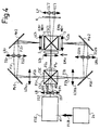
- FIG. 4 schematically shows how to use the invention in a color projector 20 with three primary colors for example, in which three modulating devices are used, that is to say three LCD matrix screens such as the matrix screen 5, with an arrangement which makes it possible to use a projection objective common to the three colors in the best conditions (drawing of the objective), with three geometric ranges of identical beams.
- a beam of white light FLB is applied to an ESE separator-orientator assembly which delivers a group GP of two complementary polarized beams of white light with which two source images IS1, IS2 are formed. These two beams correspond to the two polarized beams FP1, FP2 ′ shown in FIG. 1.
- the two polarized beams FP1, FP2 ′ of white light pass through a dichroic system, a CSC color separator cube for example, in which they generate beams of the same geometric characteristics but of narrow spectral range corresponding to red, blue and green .
- Green light is transmitted by the color separator cube: green light is formed by two beams F1 v and F2 v similar to the first and second polarized beams FP1, FP2 ′ respectively ( Figure 1). These two beams F1 v and F2 v are transmitted to the field lens LCh and the matrix screen of a modulator assembly EM v assigned to green; this EM v modulator assembly is arranged so that the two beams F1 v and F2 v (symbolized by their axis of propagation) intersect substantially at the level of the field lens.
- the red light component is reflected by the CSC color separator cube at 90 ° from green light.
- the red light is also formed by two beams F1 r and F2 r similar to the first and second polarized beams FP1, FP2 ′ respectively, but whose spectrum corresponds to red.
- the two red beams F1 r and F2 r propagate towards a modulator device assigned to red, and for this purpose they pass through a field lens LCh r which makes it possible to form intermediate source images for the red IS1 r , IS2 r , after reflection of these red beams by a plane mirror Mr1.
- a relay lens LR r provides optical conjugation between the field lens LCh r and the field lens LCh contained in the modulator assembly EM r , to which the red light arrives after a second reflection in a plane mirror M r2 .
- the third spectral component, blue light also consists of two beams F1 B AND F2 b , which propagates towards a modulator device DM b assigned to blue.
- the routing and processing of this blue component are deduced by symmetry: the two blue beams F1 b and F2 b pass through a field lens LCh b for blue, which makes it possible to form images of intermediate sources IS1 b and IS2 b for blue, after reflection of these two beams by a Mb1 plane mirror.
- a relay lens LR b provides an optical conjugation between the field lens LCh b and the field lens LC h contained in the modulator assembly EM b , the modulator assembly to which the blue light reaches after a second reflection in a plane mirror M b2 .
- the three modulator sets EM v , EM r , EM b are arranged around a dichroic system CSC1, a cube for example similar to the CSC cube and which makes it possible to superimpose or recombine the modulated beams which emerge from the three modulator sets, and orient these beams of different colors towards a common LP projection lens.
- the modulation sets EM r , EM b and EM v , the dichroic cube CSC1 and the projection objective LP, are arranged so that for each modulator set, the field lens LCh forms source images IS′1 and IS ′ 2 (to the color to which the modulator assembly is assigned) in the plane of the projection lens LP; this thanks to a selective reflection in wavelength operated in the dichroic cube CSC1.
- All the beams F1 b and F2 b , F1 r and F2 r , F1 v and F2 v have the same direction of polarization, and consequently one can use a single analyzer A common to the three colors.
- the analyzer A is placed between the dichroic cube CSC1 and the projection objective LP.
- three separate analyzers (not shown) which for example can be constituted in the form of three plastic sheets glued to the three entry faces of the CSC1 dichroic cube.
- This arrangement makes it possible to illuminate the three matrix screens 5 with beams of the same geometric characteristics.
- the luminous fluxes are routed without loss thanks to the field lenses and relay lenses.
- the geometric beam expanses are preserved. It is preferable that all the LC h field lenses are identical to each other; and preferably that all the relay lenses are identical to each other.
- FIG. 5 shows a color projector 25 according to the invention, in a configuration in which the dichroic cubes CSC and CSC1 of FIG. 5 are replaced by separate mirrors.
- the source images IS1, IS2 in white light being formed as in the examples of FIGS. 4 and 5, the group GP of two polarized beams of white light propagates towards a first selective mirror at wavelength m1 sensitive only in blue light.
- This mirror reflects the blue component F1 b and F2 b , and transmits the green and red components F1 v and F2 v , F1 r and F2 r ; thus the blue component propagates alone towards a second mirror m2, and the red and green components propagate towards a third selective mirror m3.
- the blue component F1 b , F2 b is reflected by the second mirror m3 in the direction of a matrix screen 5b assigned to the modulation of blue; the second m2 mirror is only lit by monochromatic light, green in the example, so it may not be selective.
- the green component F1 v , F2 v is reflected towards a matrix screen 5v assigned to green; while the red component F1 r , F2 r is transmitted by the third mirror m3 in the direction of a matrix screen 5r, assigned to red.
- the three components are each brought to cross the matrix screen 5r, 5b, 5v which is assigned to them, and each then constitute a group of modulated beams, GM r , GM b and GM v .
- the group GM b relating to blue successively passes through a fourth selective mirror m4 sensitive only to green, and a fifth selective mirror m5 sensitive only to red, to then arrive at the projection objective LP.
- the group GM v relating to green is reflected by the selective mirror m4, then crosses the fifth selective mirror m5 to arrive at the projection objective LP.
- the group GM r relating to red is reflected by a sixth mirror m6 selective or not, then reflected again by the selective mirror m5, in the direction of the projection objective LP.
- An analyzer can be associated with each matrix screen, or as shown in FIG. 6, a single analyzer A can be interposed, for example between the fifth selective mirror m5 and the projection objective LP.
- the advantage of this arrangement is in particular that it makes it possible to have equal distances between the images of sources IS1, IS2 and the matrix screens 5 v , 5 r , 5 b , as well as between these matrix screens and the objective of projection LP.
Description
L'invention se rapporte aux projecteurs d'images dans lesquels une modulation spatiale de la lumière est effectuée à l'aide d'un écran à cristaux liquides.The invention relates to image projectors in which spatial modulation of light is carried out using a liquid crystal screen.
Elle se rapporte plus particulièrement aux projecteurs d'images utilisant les deux directions de polarisation orthogonales et complémentaires de la lumière.It relates more particularly to image projectors using the two orthogonal and complementary directions of polarization of light.
Dans les projecteurs d'images, l'image projetée sur un écran résulte d'une modulation spatiale de la lumière. La lumière produite par une source est guidée jusqu'à un ensemble de modulation de lumière regroupant les moyens nécessaires à réaliser la modulation spatiale de la lumière. Il est courant d'utiliser en tant que modulateur spatial de lumière, un écran à cristaux liquides (en abrégé "écran matriciel LCD", de l'anglais "Liquid Crystal Display") comprenant un réseau matriciel de cellules élémentaires à cristaux liquides, commandées à partir d'un signal vidéo ; chaque cellule représentant un point élémentaire d'image.In image projectors, the image projected on a screen results from a spatial modulation of light. The light produced by a source is guided to a light modulation assembly grouping together the means necessary to achieve the spatial modulation of the light. It is common to use as a spatial light modulator, a liquid crystal screen (abbreviated as "LCD matrix screen" from the English "Liquid Crystal Display") comprising a matrix array of elementary liquid crystal cells, controlled from a video signal; each cell representing an elementary image point.
La manière la plus simple de former une image à l'aide d'un écran matriciel LCD, consiste à éclairer celui-ci par une lumière polarisée linéairement. A cet effet, il est courant d'une part, d'interposer un polariseur entre la source de lumière et l'écran matriciel LCD, afin de sélectionner une direction particulière de polarisation pour l'éclairage de l'écran matriciel LCD ; puis d'autre part de placer à la suite de l'écran matriciel LCD un second polariseur (appelé alors "analyseur de polarisation" ) qui transforme en modulation d'intensité, la modulation angulaire de polarisation produite par l'écran matriciel LCD. L'inconvénient majeur de cette méthode est que par la sélection d'une direction particulière de polarisation, pour l'éclairage de l'écran matriciel LCD, on perd plus de la moitié de l'énergie lumineuse.The simplest way to form an image using an LCD matrix screen is to illuminate it with linearly polarized light. For this purpose, it is common on the one hand, to interpose a polarizer between the light source and the LCD matrix screen, in order to select a particular direction of polarization for the lighting of the LCD matrix screen; then on the other hand to place, following the LCD matrix screen, a second polarizer (then called “polarization analyzer”) which transforms into intensity modulation, the angular polarization modulation produced by the LCD matrix screen. The major drawback of this method is that by selecting a particular direction of polarization, for lighting the LCD matrix screen, more than half of the light energy is lost.
Pour améliorer l'efficacité d'éclairage de l'écran matriciel LCD, il est connu de séparer spatialement la lumière en deux faisceaux polarisés ayant des directions de polarisations complémentaires, en vue d'utiliser toute la lumière produite par la source. A cet effet plusieurs méthodes peuvent être employées :
- a - suivant une première méthode (voir demande de brevet européen n° EP-A- 0. 372. 905), chaque faisceau polarisé éclaire un écran matriciel LCD différent ; et les images formées séparément par les deux écrans matriciels LCD sont superposées. L'inconvénient important de cette méthode et qu'elle requiert l'utilisation de deux écrans LCD, ce qui conduit à un coût très élevé du projecteur d'image ;
- b - une autre méthode consiste à faire tourner de 90° la direction de polarisation de l'un des deux faisceaux polarisés, pour que dans les deux faisceaux polarisés la direction de polarisation soit la même ; puis de diriger ensuite les deux faisceaux de manière à éclairer l'écran matriciel LCD. Une telle structure est montrée et décrite dans le compte-rendu de conférence "EURODISPLAY", page 90, organisé en 1990 par S.I.D. à Amsterdam.
- a - according to a first method (see European patent application No. EP-A-0, 372,905), each polarized beam illuminates a different LCD matrix screen; and the images formed separately by the two LCD matrix screens are superimposed. The major drawback of this method is that it requires the use of two LCD screens, which leads to a very high cost of the image projector;
- b - another method consists in rotating the direction of polarization by 90 ° of one of the two polarized beams, so that in the two polarized beams the direction of polarization is the same; then direct the two beams so as to illuminate the LCD matrix screen. Such a structure is shown and described in the conference report "EURODISPLAY", page 90, organized in 1990 by SID in Amsterdam.
La structure décrite dans le document ci-dessus mentionné présente au moins un inconvénient important, qui réside dans le fait qu'elle conduit, soit à un encombrement relativement important du projecteur, ( distance entre l'élément séparateur de polarisation et l'écran matriciel LCD) afin d'éviter que les deux faisceaux se propageant vers l'écran matriciel LCD en formant entre eux un angle relativement important ; soit à l'obligation d'utiliser un objectif de projection à grande ouverture. Un autre inconvénient de cette structure est qu'elle ne permet pas de conférer des chemins optiques symétriques aux deux faisceaux polarisés, de sorte qu'il est difficile de parfaitement superposer sur le même écran matriciel LCD, les tâches d'éclairage formées par ces deux faisceaux, c'est-à-dire de superposer les sections de ces deux faisceaux.The structure described in the above-mentioned document has at least one significant drawback, which resides in the fact that it leads, either to a relatively large size of the projector, (distance between the polarization splitter element and the matrix screen LCD) to prevent the two beams propagating towards the LCD matrix screen by forming a relatively large angle between them; or the obligation to use a projection lens with large aperture. Another drawback of this structure is that it does not allow symmetrical optical paths to be given to the two polarized beams, so that it is difficult to perfectly superimpose on the same screen. LCD matrix, the lighting tasks formed by these two beams, that is to say superimposing the sections of these two beams.
La présente invention se rapporte à un projecteur d'images du type dans lequel l'éclairage de l'écran matriciel LCD est réalisé par deux faisceaux polarisés, après rotation de 90° de la direction de polarisation de l'un de ces deux faisceaux.The present invention relates to an image projector of the type in which the illumination of the LCD matrix screen is produced by two polarized beams, after rotation of 90 ° in the direction of polarization of one of these two beams.
L'invention propose un agencement nouveau d'un tel ensemble de modulation, agencement qui permet notamment de conférer un faible encombrement à l'ensemble de modulation, tout en permettant l'utilisation d'un objectif de projection ayant une faible ouverture.The invention proposes a new arrangement of such a modulation assembly, an arrangement which in particular makes it possible to confer a small bulk to the modulation assembly, while allowing the use of a projection objective having a small aperture.
L'invention s'applique aussi bien aux projecteurs d'images de type dit "frontal" (réflexion diffusante de la lumière projetée sur l'écran de projection), que de type dit "par l'arrière" (transmission diffusante de la lumière projetée sur l'écran de projection). L'invention s'applique en outre aussi bien à réaliser des images monochromes que des images couleurs.The invention applies equally to image projectors of the so-called "frontal" type (diffusing reflection of the light projected on the projection screen), as of the so-called "rear" type (diffusing transmission of the light projected on the projection screen). The invention also applies equally well to producing monochrome images as color images.
Suivant l'invention, un projecteur d'images comportant au moins un écran matriciel à cristaux liquides, au moins un élément rotateur de direction de polarisation, au moins un séparateur de polarisation séparant la lumière en deux faisceaux polarisés ayant l'un par rapport à l'autre des directions de polarisation orthogonales, les deux faisceaux polarisés étant destinés à être modulés par l'écran matriciel après que l'un de ces faisceaux ait traversé l'élément rotateur, est caractérisé en ce qu'il comporte, d'une part des premiers moyens pour réaliser au moins deux réflexions pour chaque faisceau polarisé, une première réflexion réfléchissant le faisceau en direction d'un axe optique sur lequel est centré l'écran matriciel, et une seconde réflexion le réfléchissant ensuite en direction de l'écran matriciel, et en ce qu'il comporte d'autre part des seconds moyens pour rendre convergent chaque faisceau polarisé sur au moins une partie de son trajet compris entre le séparateur de polarisation et l'écran matriciel, de manière que chaque faisceau polarisé forme une image de la source de lumière entre la première réflexion et l'écran matriciel.According to the invention, an image projector comprising at least one liquid crystal matrix screen, at least one polarization direction rotator element, at least one polarization splitter separating the light into two polarized beams having one with respect to the other of the orthogonal polarization directions, the two polarized beams being intended to be modulated by the matrix screen after one of these beams has passed through the rotator element, is characterized in that it comprises, part of the first means for carrying out at least two reflections for each polarized beam, a first reflection reflecting the beam towards an optical axis on which the matrix screen is centered, and a second reflection then reflecting it towards the screen matrix, and in that it also comprises second means for making each polarized beam converge on at least part of its path between the polarization splitter and the matrix screen, so that each polarized beam forms an image of the light source between the first reflection and the matrix screen.
Cette disposition permet notamment d'orienter les deux faisceaux polarisés en direction de l'écran matriciel, par des miroirs situés très près de l'axe optique principal, de telle sorte que les deux faisceaux polarisés forment entre eux un angle faible, et que chaque faisceau polarisé forme une image de la source de lumière à proximité de l'axe optique.This arrangement makes it possible in particular to orient the two polarized beams in the direction of the matrix screen, by mirrors situated very close to the main optical axis, so that the two polarized beams form a small angle between them, and that each polarized beam forms an image of the light source near the optical axis.
Cette disposition offre en outre l'avantage de permettre une parfaite symétrie dans les trajets des deux faisceaux polarisés.This arrangement also offers the advantage of allowing perfect symmetry in the paths of the two polarized beams.
L'invention sera mieux comprise à la lecture de la description qui suit de certains de ses modes de réalisation, description faite en référence aux figures annexées parmi lesquelles :
- la figure 1 montre de façon schématique, un projecteur suivant l'invention, permettant de projeter des images monochromes ;
- la figure 2 montre schématiquement un projecteur conforme à l'invention, permettant de projeter des images couleurs ;
- la figure 3 montre un projecteur d'images couleurs utilisant un unique ensemble séparateur ;
- la figure 4 montre schématiquement une seconde version d'un projecteur d'images couleurs du type montré à la figure 3 ;
- la figure 5 montre schématiquement un projecteur d'images couleurs du type montré à la figure 3, mais utilisant des miroirs séparés sélectifs en longueur d'onde.
- Figure 1 shows schematically, a projector according to the invention, for projecting monochrome images;
- FIG. 2 schematically shows a projector according to the invention, making it possible to project color images;
- Figure 3 shows a color image projector using a single separator assembly;
- Figure 4 schematically shows a second version of a color image projector of the type shown in Figure 3;
- FIG. 5 schematically shows a color image projector of the type shown in FIG. 3, but using separate mirrors which are selective in wavelength.
La figure 1 montre le schéma d'un projecteur d'images 1 conforme à l'invention, de type monochrome.FIG. 1 shows the diagram of an image projector 1 according to the invention, of the monochrome type.
Le projecteur 1 comporte une source de lumière 2 produisant un faisceau FS de lumière dit faisceau source, dont la lumière ne comporte pas de direction particulière de polarisation. De façon classique les rayons du faisceau source sont pratiquement parallèles. A cet effet par exemple, la source de lumière peut être constituée par une lampe d'éclairage (non représentée) placée au foyer d'un réflecteur parabolique (non représenté), ou bien encore au foyer d'une lentille convergente.The projector 1 comprises a
Le faisceau source FS se propage suivant un axe de propagation x1, en direction d'un séparateur de polarisation SP. Le séparateur de polarisation SP peut être d'un type classique ; il peut être constitué par exemple par une surface séparatrice de polarisation SP formée par un empilement de films en couches minces de matériaux diélectriques, de manière à faire alterner différents indices de réfraction suivant une technique conventionnelle. On trouve couramment dans le commerce de telles surfaces séparatrices de polarisation réalisées dans des cubes appelés "cubes séparateurs de polarisation".The source beam FS propagates along a propagation axis x1, in the direction of a polarization splitter SP. The polarization splitter SP can be of a conventional type; it can be constituted for example by a polarization separating surface SP formed by a stack of films in thin layers of dielectric materials, so as to alternate different refractive indices according to a conventional technique. There are commonly found in the trade such polarization separating surfaces produced in cubes called "polarization separator cubes".
Dans l'exemple non limitatif décrit, la surface séparatrice SP est située sur l'axe de propagation x1 et forme avec ce dernier un angle a1 de 45°. La surface séparatrice SP décompose le faisceau source FS en deux faisceaux polarisés FP1, FP2 d'intensité pratiquement égale, mais dont les directions de polarisation sont perpendiculaires.In the nonlimiting example described, the separating surface SP is located on the propagation axis x1 and forms with the latter an angle a1 of 45 °. The separating surface SP decomposes the source beam FS into two polarized beams FP1, FP2 of practically equal intensity, but whose polarization directions are perpendicular.
Le premier faisceau polarisé FP1 est un faisceau transmis qui, ayant traversé la surface séparatrice SP, se propage suivant le premier axe de propagation x1 en direction d'un miroir M1. La lumière qui constitue le premier faisceau polarisé FP1 a une direction de polarisation P parallèle au plan d'incidence sur SP (le plan d'incidence étant le plan qui contient le rayon incident moyen de FS c'est-à-dire l'axe x1, et la normale à la surface séparatrice SP).The first polarized beam FP1 is a transmitted beam which, having crossed the separating surface SP, propagates along the first axis of propagation x1 in the direction of a mirror M1. The light which constitutes the first polarized beam FP1 has a direction of polarization P parallel to the plane of incidence on SP (the plane of incidence being the plane which contains the mean incident ray of FS, that is to say the axis x1, and the normal to the separating surface SP).
Le second faisceau polarisé FP2 est un faisceau réfléchi par la surface séparatrice SP suivant un second axe de propagation x2, en direction également d'un miroir M2. Le second axe x2 de propagation forme un angle a2 de sensiblement 90° avec la première direction de propagation x1. Le second faisceau polarisé FP2 a une direction de polarisation S perpendiculaire au plan d'incidence, c'est-à-dire qu'elle est orthogonale à celle du premier faisceau polarisé FP1.The second polarized beam FP2 is a beam reflected by the separating surface SP along a second propagation axis x2, also in the direction of a mirror M2. The second axis x2 of propagation forms an angle a2 of substantially 90 ° with the first direction of propagation x1. The second polarized beam FP2 has a polarization direction S perpendicular to the plane of incidence, that is to say that it is orthogonal to that of the first polarized beam FP1.
Les deux faisceaux polarisés FP1, FP2 sont destinés à éclairer un écran matriciel 5 LCD, comportant de façon classique une pluralité de cellules à cristaux liquides du type "nématique en hélice à 90°", disposées en lignes et en colonnes. Pour simplifier la figure, seulement cinq cellules C1 à C5 à cristaux liquides sont représentées formant une colonne, chaque cellule C1 à C5 symbolise une ligne de cellules qui s'étend perpendiculairement au plan de la figure.The two polarized beams FP1, FP2 are intended to illuminate a
Les deux faisceaux polarisés FP1, FP2 doivent être modulés par le même écran matriciel 5. A cette fin, un élément rotateur de polarisation RP est interposé sur le trajet de l'un ou l'autre de ces deux faisceaux polarisés, afin de faire tourner de 90° la polarisation de la lumière formant le faisceau choisi. Dans l'exemple non limitatif décrit, l'élément rotateur RP est disposé sur le trajet du second faisceau polarisé FP2, sur le second axe de propagation x2 et entre la surface séparatrice SP et le miroir M2, afin de faire tourner de 90° la direction de polarisation de ce faisceau, et l'amener du type S au type P. Par suite, le second faisceau polarisé émerge de l'élément rotateur RP suivant un faisceau repéré FP2′ dont la direction de polarisation est du type P, c'est-à-dire identique à celle du premier faisceau polarisé FP1.The two polarized beams FP1, FP2 must be modulated by the
On obtient donc deux faisceaux polarisés FP1, et FP2′ se propageant suivant deux directions perpendiculaires entre elles et ayant des directions de polarisation P identiques. (Pour simplifier la figure 1, on a représenté que partiellement les limites du premier faisceau polarisé FP1).We thus obtain two polarized beams FP1, and FP2 ′ propagating in two directions perpendicular to each other and having identical polarization directions P. (To simplify Figure 1, only the limits of the first polarized beam FP1 have been shown).
Suivant une caractéristique de l'invention, les deux faisceaux polarisés FP1, FP2′ sont réfléchis chacun une première fois, par les premiers miroirs M1, M2, en direction d'un axe optique principal xP sur lequel est centré l'écran matriciel 5, puis ils sont réfléchis chacun une seconde fois, à l'aide de seconds miroirs M3, M4, en direction de l'écran matriciel 5.According to a characteristic of the invention, the two polarized beams FP1, FP2 ′ are each reflected a first time, by the first mirrors M1, M2, in the direction of a main optical axis xP on which the
Suivant une autre caractéristique de l'invention, les deux faisceaux FP1, FP2′ sont rendus convergents, de manière à ce qu'ils puissent chacun former une image IS1, IS2 (symbolisées sur la figure par un ovale) de la source, de préférence à proximité de l'axe optique principal xP ; d'où il résulte que ces deux faisceaux FP1, FP2 peuvent être renvoyés vers l'écran matriciel 5 en formant entre eux un angle a3 relativement faible.According to another characteristic of the invention, the two beams FP1, FP2 ′ are made convergent, so that they can each form an image IS1, IS2 (symbolized in the figure by an oval) of the source, preferably near the main optical axis xP; where it follows that these two beams FP1, FP2 can be returned to the
Suivant une autre caractéristique de l'invention, la surface séparatrice de polarisation SP est située dans un plan perpendiculaire à celui de l'écran matriciel 5. En outre, le plan de la surface séparatrice SP contient l'axe optique principal xP et constitue un plan de symétrie de l'ensemble formé par l'écran matriciel 5, les miroirs M1, M2, M3, M4 et les moyens de convergence des faisceaux. La disposition relative de ces éléments pourrait être différente, mais cette disposition permet de conférer aux trajets des deux faisceaux polarisés FP1, FP2, une parfaite symétrie, par rapport à l'axe optique principal, ce qui facilite une parfaite superposition sur l'écran matriciel 5, des deux faisceaux polarisés FP1, FP2′.According to another characteristic of the invention, the polarization splitting surface SP is located in a plane perpendicular to that of the
Dans l'exemple non limitatif décrit, les deux faisceaux polarisés FP1, FP2′ sont dirigés par les premiers miroirs M1, M2 vers un même point de convergence PC situé sur l'axe optique principal xP. L'orientation des premiers miroirs M1, M2 est telle, que les deux faisceaux FP1, FP2′ se propagent suivant des axes x4, x5 confondus et qui sont perpendiculaires à l'axe optique principal xP.In the nonlimiting example described, the two polarized beams FP1, FP2 ′ are directed by the first mirrors M1, M2 to the same point of convergence PC located on the main optical axis xP. The orientation of the first mirrors M1, M2 is such that the two beams FP1, FP2 ′ propagate along axes x4, x5 combined and which are perpendicular to the main optical axis xP.
Après réflexion par les seconds miroirs M3, M4, le premier et le second faisceaux polarisés FP1, FP2′ se propagent en direction de l'écran matriciel 5, suivant respectivement un axe x6 et un axe x7. Ces deux axes de propagation x6, x7 convergent l'un vers l'autre afin de se croiser dans le plan de l'écran matriciel 5 ou à proximité de ce plan.After reflection by the second mirrors M3, M4, the first and the second polarized beams FP1, FP2 ′ propagate in the direction of the
Dans l'exemple non limitatif représenté à la figure 1, la convergence des deux faisceaux polarisés FP1, FP2′ est réalisée à l'aide d'une première et d'une seconde lentilles convergentes LC1, LC2, disposées respectivement sur le trajet du premier et du second faisceaux polarisés FP1, FP2′, à proximité de la surface séparatrice de polarisation SP.In the nonlimiting example represented in FIG. 1, the convergence of the two polarized beams FP1, FP2 ′ is carried out using a first and a second converging lens LC1, LC2, arranged respectively on the path of the first and of the second polarized beams FP1, FP2 ′, near the polarization splitting surface SP.
Les lentilles convergentes LC1, LC2 sont prévues par exemple pour focaliser les deux faisceaux FP1,, FP2′ au point de convergence PC, et la réflexion de ces deux faisceaux sur les seconds miroirs M3, M4 conduit à former les images de source IS1, IS2 sur les axes de propagation x6, x7, à des positions cependant très proches de l'axe optique principal xP. Bien entendu il est possible aussi que ces deux faisceaux FP1, FP2′ convergent en deux points différents (non représentés), à condition que ces deux points de convergence soient symétriques l'un par rapport à l'autre (c'est-à-dire symétriques par rapport au plan de la surface séparatrice SP.The converging lenses LC1, LC2 are provided for example to focus the two beams FP1 ,, FP2 ′ at the point of convergence PC, and the reflection of these two beams on the second mirrors M3, M4 leads to forming the source images IS1, IS2 on the propagation axes x6, x7, at positions however very close to the main optical axis xP. Of course it is also possible that these two beams FP1, FP2 ′ converge at two different points (not shown), provided that these two points of convergence are symmetrical with respect to each other (that is to say say symmetrical with respect to the plane of the separating surface SP.
Il est à noter que l'orientation des premiers miroirs M1, M2 pourrait aussi être différente, de manière que le point de convergence PC soit situé plus près ou plus loin de l'écran matriciel 5, l'important étant qu'en fonction de l'ouverture angulaire présentée par les deux faisceaux polarisés (telle que l'ouverture angulaire a6 montrée pour le faisceau FP2′), la distance D rapportée sur l'axe optique principal xP, entre l'écran matriciel 5 et les points images IS1, IS2, soit appropriée à ce que ces faisceaux éclairent pleinement sans déborder, la surface de l'écran matriciel 5, afin que toute l'énergie limineuse passe par ce dernier.It should be noted that the orientation of the first mirrors M1, M2 could also be different, so that the point of convergence PC is located closer or further from the
Dans l'exemple non limitatif décrit, une lentille de champ LCh est disposée sur l'axe optique principal xP à proximité de l'écran matriciel 5, entre ce dernier et les seconds miroirs M3, M4. Plus précisément la lentille de champ LCh est située sensiblement au point de croisement des deux axes de propagation x6, x7. La lentille de champ LCh a pour fonction de former des images IS′1 et IS′2 de la source, dans le plan de la pupille d'entrée d'un objectif ou système de projection LP, ( représenté schématiquement sur la figure par une lentille) situé sur l'axe optique principal xP, à l'opposé de la lentille de champ LCh par rapport à l'écran matriciel 5. Le grandissement de cette conjugaison optique est tel que IS′1 et IS′2 s'inscrivent entièrement dans l'ouverture de l'objectif de projection LP. Ainsi, toute l'énergie issue de la source 2 et limitée par les condenseurs ou lentilles convergentes LC1 et LC2, traverse sans perte les lentilles LCh et LP. Il est à noter que si nécessaire, une lentille dite "lentille relais" LR. peut être placée dans le plan contenant les deux premières images IS1, IS2 de source, ou dans un plan très voisin, de manière à former une image des lentilles convergentes LC1 et LC2 dans le plan de la lentille de champ LCH ; la lentille relais LR étant prévue pour permettre à toute l'énergie lumineuse issue des lentilles convergentes LC1, LC2 de traverser la lentille de champ LCh.In the nonlimiting example described, a field lens LCh is placed on the main optical axis xP near the
Les cellules C1 à C5 à cristaux liquides de l'écran matriciel 5 sont commandées de façon en elle-même classique (non représentée), par exemple par un signal vidéo. Cette commande des cellules C1 à C5 résulte en une modulation angulaire de la direction de polarisation des rayons lumineux qui traversent ces cellules, c'est-à-dire sur les rayons qui constituent les deux faisceaux polarisés FP1, FP2′. Cette modulation angulaire est transformée en modulation d'intensité d'une façon en elle-même classique, à l'aide d'un analyseur de polarisation A, lequel analyseur a pour fonction de sélectionner une direction particulière de polarisation (l'analyseur fonctionne dans ce cas comme un polariseur ).The liquid crystal cells C1 to C5 of the
Ainsi, si on observe l'écran matriciel 5 à travers l'analyseur A, on voit l'image vidéo, image qui peut être projetée sur un écran de projection EP, à l'aide de l'objectif de projection LP.Thus, if we observe the
Dans l'exemple montré à la figure 1, l'écran matriciel 5 est éclairé par des rayons convergents, mais il pourrait aussi être éclairé par des rayons lumineux parallèles ou de faible inclinaison, par exemple en choisissant la lentille de champ LCh telle que les images IS1 et IS2 soient dans son plan focal objet. On peut dans ce cas placer une seconde lentille de champ LCh′ (montrée en traits pointillés) à la suite de l'écran matriciel 5 ou à la suite de l'analyseur A, de manière à former les images IS′1 et IS′2 dans le plan de l'objectif de projection LP.In the example shown in Figure 1, the
Dans l'exemple montré à la figure 1, l'élément rotateur de polarisation RP est placé sur le trajet de second faisceau polarisé FP2, afin de conférer une même direction de polarisation aux deux faisceaux polarisés. Bien entendu, ceci peut être obtenu également en faisant tourner la direction de polarisation du premier faisceau polarisé FP1. Dans ce cas : il n'y a pas d'élément rotateur de polarisation sur le trajet du second faisceau FP2 qui conserve la direction de polarisation de type S (représentée perpendiculaire au plan de la figure) ; par contre un élément rotateur doit alors être interposé sur le trajet du premier faisceau polarisé FP1 pour faire tourner de 90° sa direction de polarisation, et l'amener du type P au type S.In the example shown in FIG. 1, the polarization rotator element RP is placed on the path of the second polarized beam FP2, in order to give the same polarization direction to the two polarized beams. Of course, this can also be obtained by rotating the direction of polarization of the first polarized beam FP1. In this case: there is no polarization rotator element in the path of the second beam FP2 which retains the polarization direction of type S (shown perpendicular to the plane of the figure); on the other hand, a rotator element must then be interposed on the path of the first polarized beam FP1 to rotate its direction of polarization by 90 °, and bring it from type P to type S.
Il est à noter que la rotation de direction de polarisation de 90° peut être accomplie, de façon classique, à l'aide d'un rotateur du type formé par une lame cristalline, dite "lame demi-onde". Cependant une telle lame a le désavantage d'être chromatique, c'est-à-dire qu'elle ne fonctionne correctement que pour une longueur d'onde, et pour une bande passante spectrale relativement étroite autour de cette longueur d'onde. Suivant une caractéristique de l'invention, l'élément rotateur de polarisation RP est constitué par une cellule à cristaux liquides, de type "nématique en hélice à 90°" fonctionnant suivant un mode dit guide d'onde ; une telle cellule remplit la fonction recherchée tout en étant moins coûteuse et moins chromatique. Bien entendu, une telle cellule doit être convenablement orientée par rapport aux directions de propagation et de polarisation de l'un ou l'autre des deux faisceaux polarisés FP1, FP2.It should be noted that the rotation of the polarization direction by 90 ° can be accomplished, in a conventional manner, using a rotator of the type formed by a crystalline plate, called "half-wave plate". However, such a plate has the disadvantage of being chromatic, that is to say that it functions correctly only for one wavelength, and for a relatively narrow spectral bandwidth around this wavelength. According to a characteristic of the invention, the RP polarization rotator element consists of a liquid crystal cell, of the "nematic 90 ° helix" type operating in a so-called waveguide mode; such a cell fulfills the desired function while being less expensive and less chromatic. Of course, such a cell must be properly oriented relative to the directions of propagation and polarization of one or the other of the two polarized beams FP1, FP2.
Il est à noter que la surface séparatrice de polarisation SP peut être réalisée de façon traditionnelle dans un cube séparateur CSP, et dans ce cas il est avantageux de disposer l'élément rotateur RP contre une face du cube séparateur CSP.It should be noted that the polarization separating surface SP can be produced in the traditional way in a separating cube CSP, and in this case it is advantageous to have the rotator element RP against one face of the separating cube CSP.
Il est à noter en outre que la convergence de chaque faisceau polarisé FP1, FP2′ peut être obtenu autrement qu'à l'aide des lentilles convergentes LC1, LC2. Par exemple, on peut utiliser un miroir parabolique MP1, MP2 (symbolisé en traits pointillés sur la figure 1) à la place de chacun des premiers miroirs M1, M2 ; dans ce cas les lentilles convergentes LC1, LC2 peuvent être supprimées.It should also be noted that the convergence of each polarized beam FP1, FP2 ′ can be obtained other than by means of the converging lenses LC1, LC2. For example, one can use a parabolic mirror MP1, MP2 (symbolized by dotted lines in FIG. 1) in place of each of the first mirrors M1, M2; in this case the converging lenses LC1, LC2 can be omitted.
On peut remarquer enfin que les seconds miroirs M3, M4 servant à orienter les deux faisceaux polarisés vers l'écran matriciel 5, peuvent avantageusement être formés sur les deux faces d'un prisme 12 ; ce qui permet notamment de leur conférer un encombrement réduit, et permet facilement de les disposer et les orienter de façon symétrique.Finally, it can be noted that the second mirrors M3, M4 serving to orient the two polarized beams towards the
L'exemple de la figure 1 s'applique à un projecteur monochrome, fonctionnant par exemple avec une lumière blanche ou monochromatique. Mais les avantages apportés par l'invention sont encore amplifiés dans le cas d'un projecteur d'images couleur, où il est nécessaire de multiplier plusieurs des fonctions assurées dans un projecteur monochrome.The example in FIG. 1 applies to a monochrome projector, operating for example with white or monochromatic light. However, the advantages provided by the invention are further amplified in the case of a color image projector, where it is necessary to multiply several of the functions provided in a monochrome projector.
Ainsi plusieurs fonctions principales peuvent être soulignées dans le projecteur 1 de la figure 1, parmi lesquelles certaines doivent reproduites plusieurs fois dans un projecteur couleur :
- Parmi ces fonctions principales, il y a la séparation des polarisations P, S orthogonales suivant deux faisceaux polarisés FP1, FP2 ou FP2′, dont on assure ensuite la convergence, de manière qu'après au moins deux réflexions de chacun de ces faisceaux, ils soient orientés vers l'écran matriciel 5 en formant chacun une image IS1, IS2 de la source à proximité de l'axe optique principal xP. Pour faciliter la suite de la description, d'une part les éléments qui assurent ces fonctions sont regroupés dans un ensemble appelé "ensemble séparateur-orienteur" ESE ; et d'autre part les premier et second faisceaux polarisés FP1, FP2′, après leur réflexion respectivement par les seconds miroirs M3, M4 pour les orienter en direction de l'écran matriciel 5, constituent un groupe de deux faisceaux polarisés GP.Several main functions can therefore be highlighted in the projector 1 in FIG. 1, some of which must be reproduced several times in a color projector:
- Among these main functions, there is the separation of the orthogonal P, S polarizations along two polarized beams FP1, FP2 or FP2 ′, of which we then ensure convergence, so that after at least two reflections from each of these beams, they are oriented towards the
Une autre fonction importante à distinguer est la fonction de modulation remplie par l'écran matriciel 5 : l'écran matriciel 5 et la lentille de champ LCh (et éventuellement si elle est installée, la lentille de champ LCh′) sont groupés dans un autre ensemble appelé "ensemble de modulation" EM. En ce qui concerne les premier et second faisceaux polarisés FP1, FP2′ qui traversent l'écran matriciel 5, ils émergent de ce dernier en constituant respectivement un premier et un second faisceaux modulés FM1, FM2 représentés par les axes suivant lesquels ils se propagent (en effet, pour plus de clarté de la figure 1, seules les limites du second faisceau modulé FM2 sont représentées). Ces deux faisceaux modulés FM1, FM2 sont destinés à former une même image, et dans la suite de la description ils sont appelés "groupe de faisceaux modulés GM".Another important function to distinguish is the modulation function fulfilled by the matrix screen 5: the
Enfin un ensemble séparateur-orienteur ESE suivi d'un ensemble modulateur EM comme montré à la figure 1, est appelé "dispositif monochrome " DM.Finally, an ESE separator-orienter assembly followed by an EM modulator assembly as shown in FIG. 1, is called "monochrome device" DM.
La figure 2 montre de façon schématique une application de l'invention à un projecteur 10 d'images couleur, dans lequel la couleur résulte de la combinaison de plusieurs couleurs primaires, telles que par exemple rouge, vert et bleu.FIG. 2 schematically shows an application of the invention to a
Le projecteur 10 comporte un premier, un second et un troisième dispositifs monochromes DMr, DMv, DMb affectés respectivement à traiter une lumière de couleur rouge, verte et bleue. Chaque dispositif monochrome est semblable à celui montré à la figure 1, et comprend un axe de propagation x1 sur lequel se propage un faisceau de lumière monochrome non polarisée, Fr1, Fv1, Fb1, dont le spectre correspond à la couleur du dispositif monochrome correspondant. Chacun de ces faisceaux monochromes non polarisés peut être produit à partir d'une source de lumière particulière, ou comme montré sur la figure 2, à partir d'une unique source de lumière blanche 2a. Dans ce dernier cas, le faisceau de lumière blanche FLB est séparé en trois faisceaux monochromes Fr1, Fv1, Fb1 de couleurs différentes, à l'aide d'éléments sélectifs en longueur d'ondes tels que notamment des filtres dichroïques ; par exemple à l'aide d'un cube dichroïque CSC classique, dans lequel par exemple : un miroir sélectif en longueur d'onde MSr réfléchit une composante rouge formant le faisceau monochrome Fr1, lequel se propage en direction du dispositif monochrome DMr après réflexion par un miroir plan MP₁ ; un autre miroir sélectif MSb réfléchit une composante bleue formant le faisceau monochrome Fb1, lequel se propage en direction du dispositif monochrome DMb après réflexion par un miroir plan MP₂ ; la composante verte formant le faisceau Fv1 étant transmise, directement en direction du dispositif monochrome DMv.The
Chaque dispositif monochrome est suivi d'un analyseur Ar, Av, Ab et d'un objectif de projection LPr, LPv, LPb, de manière que les trois images de couleurs différentes, contenues dans les groupes GMr, GMb et GMv de faisceaux modulés soient superposées sur l'écran de projection EP.Each monochrome device is followed by an analyzer A r , A v , A b and a projection objective LP r , LP v , LP b , so that the three images of different colors, contained in the groups GM r , GM b and GM v of modulated beams are superimposed on the projection screen EP.
La figure 3 montre schématiquement un projecteur couleur 15 qui permet d'utiliser un unique ensemble séparateur-orienteur ESE, pour plusieurs ensembles de modulations affectés à traiter des couleurs différentes.FIG. 3 schematically shows a color projector 15 which makes it possible to use a single ESE separator-orienter assembly, for several sets of modulations assigned to process different colors.
La source de lumière 2a produit un faisceau de lumière blanche FLB, non polarisée. Le faisceau de lumière blanche FLB est appliqué à un ensemble séparateur-orienteur ESE semblable à celui de la figure 1, d'une même manière qu'est appliqué le faisceau source FS (sur la figure 1).The
L'ensemble séparateur-orienteur ESE délivre un groupe de deux faisceaux polarisés GP formé par un premier et un second faisceaux polarisés (non représentés sur la figure 3) ayant des directions de polarisation P identiques, comme dans le cas des deux faisceaux polarisés FP1, FP2′ ; ces deux faisceaux ayant formés chacun une image IS1, IS2, de part et d'autre d'un axe optique AO, lequel axe optique AO correspond à l'axe optique principal xP montré sur la figure 1.The ESE separator-orienter assembly delivers a group of two polarized beams GP formed by a first and a second polarized beams (not shown in FIG. 3) having identical polarization directions P, as in the case of the two polarized beams FP1, FP2 ′; these two beams having each formed an image IS1, IS2, on either side of an optical axis AO, which optical axis AO corresponds to the main optical axis xP shown in FIG. 1.
Les images de source IS1, IS2 étant formées en lumière blanche, on sépare ensuite les trois couleurs primaires r, b, v pour éclairer avec chacune un écran matriciel (non représenté sur la figure 3) tel que l'écran matriciel 5 montré à la figure 1 ; chacun de ces écrans matriciels est disposé dans un premier, second et troisième ensembles modulateurs EMr, EMb et EMv affectés respectivement au rouge, au bleu et au vert. A cet effet, le groupe GP de deux faisceaux polarisés passe par un dispositif séparateur de couleurs en lui-même classique, tel qu'un cube dichroïque CSC semblable à celui déjà montré à la figure 2. Ce dernier d'une part réfléchit les composantes rouge, et bleue respectivement suivant un premier et second axes optiques monochromes xMr, xMb en direction du premier et du second ensemble de modulation EMr, EMb, par l'intermédiaire d'un premier et d'un second miroirs plans MP1, MP2 ; et d'autre part il transmet la composante verte vers le troisième ensemble modulateur EMv, suivant un troisième axe optique monochrome xMv. Bien entendu ces composantes rouge, bleue et verte étant constituées à partir d'un groupe GP de deux faisceaux polarisés tels que FP1, FP2′, elles sont chacune sous la forme de deux faisceaux polarisés (non représentés) ayant une même direction de polarisation, et qui sont chacun des faisceaux divergents et dont les axes se croisent sensiblement dans le plan de l'écran matriciel, comme c'est le cas des deux faisceaux polarisés FP1, FP2′ (montrés figure 1) dans leur trajet entre les seconds miroirs M3, M4 et l'écran matriciel 5.The source images IS1, IS2 being formed in white light, the three primary colors r, b, v are then separated to illuminate with each a matrix screen (not shown in FIG. 3) such as the
Chaque ensemble modulateur EM délivre un groupe de faisceaux modulés GMr, GMb, GMv en direction d'un dispositif apte à les recombiner, par l'intermédiaire d'un miroir plan MP3, MP4, pour les groupes GMr et GMb.Each modulator assembly EM delivers a group of modulated beams GM r , GM b , GM v in the direction of a device capable of recombining them, by means of a plane mirror MP3, MP4, for the groups GM r and GM b .
Les trois groupes de faisceaux modulés GMr, GMb et GMv, de couleurs primaires différentes, peuvent être superposés ou recombinés par un système dichroïque CSC1, dit de réunion (semblable par exemple au cube CSC de séparation de couleur) afin d'être projetés sur l'écran de projection EP par un objectif de projection LP unique. Mais, comme dans le cas de la figure 2, les trois images formées par les trois ensembles de modulation, peuvent aussi être projetées sur l'écran de projection EP par trois objectifs de projection séparés.The three groups of modulated beams GM r , GM b and GM v , of different primary colors, can be superimposed or recombined by a dichroic system CSC1, called meeting (similar for example to the cube CSC of color separation) in order to be projected onto the EP projection screen by a single LP projection lens. However, as in the case of FIG. 2, the three images formed by the three modulation assemblies can also be projected onto the projection screen EP by three separate projection objectives.
Il est à noter que les lentilles de champ LCh, LCh′ (non représentées à la figure 3) mentionnées en référence à la figure 1, peuvent être placées soit avant, soit après la séparation ou la superposition de couleur opérées respectivement par le cube CSC et le système dichroïque CSC1. Il peut ainsi n'y avoir qu'un seul système commun de lentilles de champ.It should be noted that the field lenses LCh, LCh ′ (not shown in FIG. 3) mentioned with reference to FIG. 1, can be placed either before or after the separation or the color superposition operated respectively by the cube CSC and the CSC1 dichroic system. There can thus be only one common system of field lenses.
De même, il peut y avoir un analyseur Ar, Ab, Av par voie, c'est-à-dire par dispositif de modulation, comme dans l'exemple de la figure 2. Mais aussi il peut y avoir un unique analyseur A commun aux trois couleurs, disposé après la superposition des trois couleurs.Similarly, there can be an analyzer A r , A b , A v per channel, that is to say by modulation device, as in the example in FIG. 2. But also there can be a single analyzer A common to the three colors, arranged after the superposition of the three colors.
La figure 4 montre schématiquement comment utiliser l'invention dans un projecteur couleur 20 à trois couleurs primaires par exemple, dans lequel on utilise trois dispositifs modulateurs, c'est-à-dire trois écrans matriciels LCD tels que l'écran matriciel 5, avec un agencement qui permet d'utiliser un objectif de projection commun aux trois couleurs dans les meilleures conditions (tirage de l'objectif), avec trois étendues géométriques de faisceaux identiques.FIG. 4 schematically shows how to use the invention in a color projector 20 with three primary colors for example, in which three modulating devices are used, that is to say three LCD matrix screens such as the
Comme dans l'exemple de la figure 3, un faisceau de lumière blanche FLB est appliqué à un ensemble séparateur-orienteur ESE qui délivre un groupe GP de deux faisceaux polarisés complémentaires, de lumière blanche, avec lesquels sont formés deux images de source IS1, IS2. Ces deux faisceaux correspondent aux deux faisceaux polarisés FP1, FP2′ montrés en figure 1.As in the example in FIG. 3, a beam of white light FLB is applied to an ESE separator-orientator assembly which delivers a group GP of two complementary polarized beams of white light with which two source images IS1, IS2 are formed. These two beams correspond to the two polarized beams FP1, FP2 ′ shown in FIG. 1.
Les deux faisceaux polarisés FP1, FP2′ de lumière blanche passent par un système dichroïque, un cube séparateur de couleurs CSC par exemple, dans lequel ils engendrent des faisceaux de mêmes caractéristiques géométriques mais de gamme spectrale étroite correspondant au rouge, au bleu et au vert.The two polarized beams FP1, FP2 ′ of white light pass through a dichroic system, a CSC color separator cube for example, in which they generate beams of the same geometric characteristics but of narrow spectral range corresponding to red, blue and green .
La lumière verte est transmise par le cube séparateur de couleurs : la lumière verte est formée par deux faisceaux F1v et F2v semblables respectivement aux premier et second faisceaux polarisés FP1, FP2′ (figure 1). Ces deux faisceaux F1v et F2v sont transmis vers la lentille de champ LCh et l'écran matriciel d'un ensemble modulateur EMv affecté au vert ; cet ensemble modulateur EMv est disposé de manière que les deux faisceaux F1v et F2v (symbolisés par leur axe de propagation) se croisent sensiblement au niveau de la lentille de champ.Green light is transmitted by the color separator cube: green light is formed by two beams F1 v and F2 v similar to the first and second polarized beams FP1, FP2 ′ respectively (Figure 1). These two beams F1 v and F2 v are transmitted to the field lens LCh and the matrix screen of a modulator assembly EM v assigned to green; this EM v modulator assembly is arranged so that the two beams F1 v and F2 v (symbolized by their axis of propagation) intersect substantially at the level of the field lens.
La composante de lumière relative au rouge est réfléchie par le cube séparateur de couleur CSC à 90° de la lumière verte. La lumière rouge est formée elle aussi de deux faisceaux F1r et F2r semblables respectivement aux premier et second faisceaux polarisés FP1, FP2′, mais dont le spectre correspond au rouge. Les deux faisceaux rouges F1r et F2r se propagent vers un dispositif modulateur affecté au rouge, et à cet effet ils passent par une lentille de champ LChr qui permet de former des images de source intermédiaires pour le rouge IS1r, IS2r, après réflexion de ces faisceaux rouges par un miroir plan Mr1. Dans le plan de ces images source intermédiaires, IS1r et IS2r, une lentille relais LRr assure une conjugaison optique entre la lentille de champ LChr et la lentille de champ LCh contenue dans l'ensemble modulateur EMr, auquel la lumière rouge parvient après une seconde réflexion dans un miroir plan Mr2.The red light component is reflected by the CSC color separator cube at 90 ° from green light. The red light is also formed by two beams F1 r and F2 r similar to the first and second polarized beams FP1, FP2 ′ respectively, but whose spectrum corresponds to red. The two red beams F1 r and F2 r propagate towards a modulator device assigned to red, and for this purpose they pass through a field lens LCh r which makes it possible to form intermediate source images for the red IS1 r , IS2 r , after reflection of these red beams by a plane mirror Mr1. In the plane of these intermediate source images, IS1 r and IS2 r , a relay lens LR r provides optical conjugation between the field lens LCh r and the field lens LCh contained in the modulator assembly EM r , to which the red light arrives after a second reflection in a plane mirror M r2 .
La troisième composante spectrale, la lumière bleue est constituée également de deux faisceaux F1B ET F2b, qui se propage en direction d'un dispositif modulateur DMb affecté au bleu. Le cheminement et le traitement de cette composante bleue se déduisent par symétrie : les deux faisceaux bleus F1b et F2b passent par une lentille de champ LChb pour le bleu, qui permet de former des images de sources intermédiaires IS1b et IS2b pour le bleu, après réflexion de ces deux faisceaux par un miroir plan Mb₁. Dans le plan de ces images source intermédiaires, une lentille relais LRb assure une conjugaison optique entre la lentille de champ LChb et la lentille de champ LCh contenue dans l'ensemble modulateur EMb, l'ensemble modulateur auquel la lumière bleue parvient après une seconde réflexion dans un miroir plan Mb2.The third spectral component, blue light also consists of two beams F1 B AND F2 b , which propagates towards a modulator device DM b assigned to blue. The routing and processing of this blue component are deduced by symmetry: the two blue beams F1 b and F2 b pass through a field lens LCh b for blue, which makes it possible to form images of intermediate sources IS1 b and IS2 b for blue, after reflection of these two beams by a Mb₁ plane mirror. In the plane of these intermediate source images, a relay lens LR b provides an optical conjugation between the field lens LCh b and the field lens LC h contained in the modulator assembly EM b , the modulator assembly to which the blue light reaches after a second reflection in a plane mirror M b2 .
Les trois ensembles modulateurs EMv, EMr, EMb sont disposés autour d'un système dichroïque CSC1, un cube par exemple semblable au cube CSC et qui permet de superposer ou recombiner les faisceaux modulés qui émergent des trois ensembles modulateurs, et d'orienter ces faisceaux de couleurs différentes en direction d'un objectif de projection LP commun.The three modulator sets EM v , EM r , EM b are arranged around a dichroic system CSC1, a cube for example similar to the CSC cube and which makes it possible to superimpose or recombine the modulated beams which emerge from the three modulator sets, and orient these beams of different colors towards a common LP projection lens.
Les ensembles de modulation EMr, EMb et EMv, le cube dichroïque CSC1 et l'objectif de projection LP, sont disposés de manière que pour chaque ensemble modulateur, la lentille de champ LCh forme des images de source IS′1 et IS′2 (à la couleur à laquelle l'ensemble modulateur est affectée) dans le plan de l'objectif de projection LP ; ceci grâce à une réflexion sélective en longueur d'onde opérée dans le cube dichroïque CSC1.The modulation sets EM r , EM b and EM v , the dichroic cube CSC1 and the projection objective LP, are arranged so that for each modulator set, the field lens LCh forms source images IS′1 and IS ′ 2 (to the color to which the modulator assembly is assigned) in the plane of the projection lens LP; this thanks to a selective reflection in wavelength operated in the dichroic cube CSC1.
Tous les faisceaux F1b et F2b, F1r et F2r, F1v et F2v ont une même direction de polarisation, et en conséquence on peut utiliser un unique analyseur A commun aux trois couleurs. Dans ce cas l'analyseur A est placé entre le cube dichroïque CSC1 et l'objectif de projection LP. Mais on peut aussi utiliser trois analyseurs séparés (non représentés) qui par exemple peuvent être constitués sous la forme de trois feuilles plastiques collées sur les trois faces d'entrée du cube dichroïque CSC1.All the beams F1 b and F2 b , F1 r and F2 r , F1 v and F2 v have the same direction of polarization, and consequently one can use a single analyzer A common to the three colors. In this case the analyzer A is placed between the dichroic cube CSC1 and the projection objective LP. But one can also use three separate analyzers (not shown) which for example can be constituted in the form of three plastic sheets glued to the three entry faces of the CSC1 dichroic cube.
Cette disposition permet d'éclairer les trois écrans matriciels 5 avec des faisceaux de mêmes caractéristiques géométriques.This arrangement makes it possible to illuminate the three
Les flux lumineux sont acheminés sans perte grâce aux lentilles de champ et aux lentilles relais. D'autre part, les étendues géométriques de faisceau sont conservées. Il est préférable que toutes les lentilles de champ LCh soient identiques entre elles ; et de préférence, que toutes les lentilles relais soient identiques entre elles.The luminous fluxes are routed without loss thanks to the field lenses and relay lenses. On the other hand, the geometric beam expanses are preserved. It is preferable that all the LC h field lenses are identical to each other; and preferably that all the relay lenses are identical to each other.
La figure 5 montre un projecteur couleur 25 conforme à l'invention, suivant une configuration dans laquelle les cubes dichroïques CSC et CSC1 de la figure 5 sont remplacés par des miroirs séparés.FIG. 5 shows a
Les images de source IS1, IS2 en lumière blanche, étant formée comme dans les exemples des figures 4 et 5, le groupe GP de deux faisceaux polarisés de lumière blanche se propage en direction d'un premier miroir sélectif en longueur d'onde m1 sensible uniquement à la lumière bleue. Ce miroir réfléchit la composante bleue F1b et F2b, et transmet les composantes vertes et rouges F1v et F2v, F1r et F2r ; ainsi la composante bleue se propage seule en direction d'un second miroir m2, et les composantes rouges et vertes se propagent en direction d'un troisième miroir sélectif m3. La composante bleue F1b, F2b est réfléchie par le second miroir m3 en direction d'un écran matriciel 5b affecté à la modulation du bleu ; le second miroir m2 n'est éclairé que par de la lumière monochromatique, verte dans l'exemple, il peut donc ne pas être sélectif. Sous l'action du troisième miroir m3 sensible uniquement au vert, la composante verte F1v, F2v est réfléchie vers un écran matriciel 5v affecté au vert ; alors que la composante rouge F1r, F2r est transmise par le troisième miroir m3 en direction d'un écran matriciel 5r, affecté au rouge. Ainsi les trois composantes sont amenées chacune à traverser l'écran matriciel 5r, 5b, 5v qui leur est affecté, et constituent chacune ensuite un groupe de faisceaux modulés, GMr, GMb et GMv. Le groupe GMb relatif au bleu traverse successivement, un quatrième miroir sélectif m4 sensible uniquement au vert, et un cinquième miroir sélectif m5 sensible uniquement au rouge, pour arriver ensuite à l'objectif de projection LP.The source images IS1, IS2 in white light, being formed as in the examples of FIGS. 4 and 5, the group GP of two polarized beams of white light propagates towards a first selective mirror at wavelength m1 sensitive only in blue light. This mirror reflects the blue component F1 b and F2 b , and transmits the green and red components F1 v and F2 v , F1 r and F2 r ; thus the blue component propagates alone towards a second mirror m2, and the red and green components propagate towards a third selective mirror m3. The blue component F1 b , F2 b is reflected by the second mirror m3 in the direction of a
Le groupe GMv relatif au vert, est réfléchi par le miroir sélectif m4, puis traverse le cinquième miroir sélectif m5 pour arriver à l'objectif de projection LP.The group GM v relating to green, is reflected by the selective mirror m4, then crosses the fifth selective mirror m5 to arrive at the projection objective LP.
Enfin, le groupe GMr relatif au rouge est réfléchi par un sixième miroir m6 sélectif ou non, puis réfléchi à nouveau par le miroir sélectif m5, en direction de l'objectif de projection LP.Finally, the group GM r relating to red is reflected by a sixth mirror m6 selective or not, then reflected again by the selective mirror m5, in the direction of the projection objective LP.
Un analyseur peut être associé à chaque écran matriciel, ou bien comme montré à la figure 6, un unique analyseur A peut être interposé, par exemple entre le cinquième miroir sélectif m5 et l'objectif de projection LP.An analyzer can be associated with each matrix screen, or as shown in FIG. 6, a single analyzer A can be interposed, for example between the fifth selective mirror m5 and the projection objective LP.
Les lentilles de champs et les lentilles relais ne sont pas représentées sur la figure 6, mais la disposition de la figure 6 est compatible avec l'utilisation de telles lentilles.Field lenses and relay lenses are not shown in Figure 6, but the arrangement of Figure 6 is compatible with the use of such lenses.
L'avantage de cette disposition est notamment qu'elle permet d'avoir des distances égales entre les images de sources IS1, IS2 et les écrans matriciels 5v, 5r, 5b, ainsi qu'entre ces écrans matriciels et l'objectif de projection LP.The advantage of this arrangement is in particular that it makes it possible to have equal distances between the images of sources IS1, IS2 and the matrix screens 5 v , 5 r , 5 b , as well as between these matrix screens and the objective of projection LP.
Bien entendu on peut envisager toute permutation des couleurs.Of course we can consider any permutation of colors.
Claims (19)
- Image projector including at least one light source (2, 2a), at least one liquid-crystal matrix screen (5), at least one polarization direction rotator element (RP), at least one polarization separator (CSP) separating the light into two polarized beams (FP1, FP2 and FP2′) having orthogonal polarization directions with respect to one another, the two polarized beams being intended to be modulated by the matrix screen after one of these beams has passed through the rotator element (RP), characterized in that it includes, on the one hand, first means (M1, M2, M3, M4) for performing at least two reflections for each polarized beam, a first reflection reflecting the beam towards an optical axis (xP) on which the matrix screen (5) is centred and a second reflection reflecting it towards the matrix screen (5), and in that it includes, on the other hand, second means (LC1, LC2) for making each polarized beam convergent over at least a part of its path lying between the polarization separator (SP) and the matrix screen (5), in such a way that each polarized beam forms an image (IS1, IS2) of the light source between the first reflection and the matrix screen (5).
- Image projector according to Claim 1, characterized in that the polarization separator (CSP) includes a polarization separating surface (SP), the plane of which is, on the one hand, perpendicular to the plane of the matrix screen (5), and, on the other hand, contains the said optical axis (xP).
- Image projector according to Claim 2, characterized in that the first means for performing the reflections of the two polarized beams (FP1, FP2′) are arranged symmetrically with respect to the optical axis (xP).
- Image projector according to one of the preceding claims, characterized in that the first means of reflecting the two polarized beams include, for each polarized beam (FP1, FP2, FP2′), a first mirror (M1, M2) reflecting the beam towards the optical axis (xP), and a second mirror (M3, M4) then reflecting the beam towards the matrix screen (5).
- Image projector according to one of the preceding claims, characterized in that the second means for making each polarized beam convergent include a first and a second converging lenses (LC1, LC2).
- Image projector according to Claim 5, characterized in that the first and second converging lenses (LC1, LC2) are arranged between the polarization separator (SP) and the first mirrors (M1, M2).
- Image projector according to Claim 4, characterized in that the first mirrors (M1, M2) are parabolic mirrors so as moreover to consititute the second means for making each polarized beam convergent.
- Image projector according to one of the preceding claims, characterized in that the polarization rotator element (RP) is a liquid-crystal cell of the "90°-twisted nematic" type.
- Image projector according to Claim 4, characterized in that the second mirrors (M3, M4) are formed on the faces of a prism (12).
- Image projector according to Claim 4, characterized in that a field lens (LCh) is arranged in proximity to the matrix screen (5), between the latter and the second mirrors (M3, M4).
- Image projector according to Claim 4, characterized in that a lens called "relay lens" (LR) is arranged in proximity to the second mirrors (M3, M4), between the latter and the matrix screen.
- Image projector according to one of the preceding claims, characterized in that, on the one hand, the orientation towards the matrix screen (5) of the two polarized beams (FP1, FP2, FP2′), is accomplished in a separating-orienting assembly (ESE), grouping together particularly the polarization separator (SP), the polarization rotator element (RP), the first means for providing two reflections of the polarized beams, and the second means for making the polarized beams convergent, the two polarized beams (FP1, FP2′) emerging from the separating-orienting assembly (ESE) constituting one group (GP) of polarized beams propagating towards the matrix screen (5), on the other hand, modulation by the matrix screen (5) is accomplished in a modulation assembly (EM), the separating-orienting assembly (ESE) interacting with at least one modulation assembly (EM).
- Image projector according to Claim 12, characterized in that it includes several monochrome devices (DMr, DMb, DMv) each formed by a separating-orienting assembly (ES) interacting with a modulator assembly (EM), each monochrome device corresponding to a different colour.
- Image projector according to Claim 13, characterized in that each monochrome device (DMv, DMb, DMr) interacts with a different projection objective.
- Image projector according to Claim 12, characterized in that it includes a separating-orienting assembly (ESE) interacting with several modulation assemblies (EMv, EMb, EMr) via a dichroic colour-separating device (CSC), each modulation assembly (EM1 to EM3) corresponding to a different colour.
- Image projector according to Claim 15, characterized in that the various modulation assemblies (EMb, EMr, EMv) interact with the same projection objective (LP), via a dichroic combining device (CSC1).
- Image projector according to Claim 15, characterized in that the various modulation assemblies (EMb, EMr, EMv) interact with the different projection objectives (LPr, LPv, LPb).
- Image projector according to Claim 16, characterized in that the modulation assemblies (EMb, EMr, EMv) are arranged around the dichroic combining device (CSC1), at an equal distance from the latter, and in that it includes third means (LChv, LChb, LChv) for forming intermediate source images (IS1r, IS2r) between at least one of the modulation assemblies and the dichroic colour-separating device (CSC).
- Image projector according to Claim 12, characterized in that it includes a separating-orienting assembly (ESE) interacting with at least three modulator assemblies (EMb, EMr, EMv) and a single projection objective (LP), by the use of at least six mirrors (m1 to m6) at least four of which are wavelength-selective mirrors, each modulator assembly corresponding to a different colour.
Applications Claiming Priority (2)
| Application Number | Priority Date | Filing Date | Title |
|---|---|---|---|
| FR9013942 | 1990-11-09 | ||
| FR9013942A FR2669127B1 (en) | 1990-11-09 | 1990-11-09 | TWO-BEAM POLARIZED IMAGE PROJECTOR BY MATRIX SCREEN. |
Publications (2)
| Publication Number | Publication Date |
|---|---|
| EP0485268A1 EP0485268A1 (en) | 1992-05-13 |
| EP0485268B1 true EP0485268B1 (en) | 1995-03-08 |
Family
ID=9402040
Family Applications (1)
| Application Number | Title | Priority Date | Filing Date |
|---|---|---|---|
| EP91402942A Expired - Lifetime EP0485268B1 (en) | 1990-11-09 | 1991-11-04 | Matrix screen image projector with two polarized beams |
Country Status (5)
| Country | Link |
|---|---|
| US (1) | US5299036A (en) |
| EP (1) | EP0485268B1 (en) |
| JP (1) | JP3093391B2 (en) |
| DE (1) | DE69107960T2 (en) |
| FR (1) | FR2669127B1 (en) |
Cited By (1)
| Publication number | Priority date | Publication date | Assignee | Title |
|---|---|---|---|---|
| US6697197B2 (en) | 1992-06-11 | 2004-02-24 | Au Optronics Corporation | High efficiency electromagnetic beam projector, and systems and methods for implementation thereof |
Families Citing this family (23)
| Publication number | Priority date | Publication date | Assignee | Title |
|---|---|---|---|---|
| US5570209A (en) * | 1990-09-18 | 1996-10-29 | Mitsubishi Denki Kabushiki Kaisha | Color projection type display apparatus having three liquid crystal displays of same structure |
| US5659409A (en) * | 1992-10-09 | 1997-08-19 | Ag Technology Co., Ltd. | Light source apparatus using a cone-like material and an applied apparatus thereof |
| FR2707444B1 (en) * | 1993-07-05 | 1995-08-18 | Thomson Csf | Liquid crystal video projector. |
| FR2707447B1 (en) * | 1993-07-09 | 1995-09-01 | Thomson Csf | Color display device. |
| FR2711878B1 (en) * | 1993-10-29 | 1995-12-15 | Thomson Csf | Color display device and production method. |
| DE69431337T2 (en) * | 1993-12-17 | 2003-05-22 | Matsushita Electric Ind Co Ltd | Liquid crystal projection device and liquid crystal display device |
| WO1996019900A1 (en) * | 1994-12-22 | 1996-06-27 | Thomson-Csf | Liquid crystal video projector |
| FR2732783B1 (en) * | 1995-04-07 | 1997-05-16 | Thomson Csf | COMPACT BACK PROJECTION DEVICE |
| IL113796A0 (en) * | 1995-05-19 | 1995-08-31 | Unic View Ltd | Projector |
| US5765934A (en) * | 1995-08-04 | 1998-06-16 | Mitsubishi Denki Kabushiki Kaisha | Projection type display |
| FR2738645B1 (en) | 1995-09-12 | 1997-10-03 | Thomson Csf | SYSTEM FOR ILLUMINATING AN ELECTROOPTIC COLOR VISUALIZATION SCREEN |
| JPH09114022A (en) * | 1995-10-12 | 1997-05-02 | Texas Instr Inc <Ti> | Projector device |
| US5975703A (en) | 1996-09-30 | 1999-11-02 | Digital Optics International | Image projection system |
| FR2755516B1 (en) | 1996-11-05 | 1999-01-22 | Thomson Csf | COMPACT ILLUMINATION DEVICE |
| US5973833A (en) * | 1997-08-29 | 1999-10-26 | Lightware, Inc. | High efficiency polarizing converter |
| US6995917B1 (en) | 1999-04-08 | 2006-02-07 | Sharp Laboratories Of America, Inc. | Projection display system using polarized light |
| FR2819061B1 (en) * | 2000-12-28 | 2003-04-11 | Thomson Csf | POLARIZATION CONTROL DEVICE IN AN OPTICAL LINK |
| US7573579B2 (en) * | 2006-10-12 | 2009-08-11 | Duke University | Coded aperture imaging photopolarimetry |
| US8348489B2 (en) * | 2008-01-30 | 2013-01-08 | Qualcomm Mems Technologies, Inc. | Thin illumination system |
| US8721149B2 (en) | 2008-01-30 | 2014-05-13 | Qualcomm Mems Technologies, Inc. | Illumination device having a tapered light guide |
| US8534841B2 (en) * | 2010-05-21 | 2013-09-17 | Sony Corporation | 3D optical projection device |
| JP5910031B2 (en) * | 2011-11-28 | 2016-04-27 | ソニー株式会社 | Projection device |
| CN114815236A (en) * | 2021-01-27 | 2022-07-29 | 怡利电子工业股份有限公司 | Symmetrical light path 3D head-up display |
Family Cites Families (14)
| Publication number | Priority date | Publication date | Assignee | Title |
|---|---|---|---|---|
| US4127322A (en) * | 1975-12-05 | 1978-11-28 | Hughes Aircraft Company | High brightness full color image light valve projection system |
| JP2580104B2 (en) * | 1984-10-09 | 1997-02-12 | ソニー株式会社 | Projection type display device |
| JPH061303B2 (en) * | 1984-11-20 | 1994-01-05 | ソニー株式会社 | Polarized illumination device |
| EP0258927A3 (en) * | 1986-08-22 | 1991-01-09 | North American Philips Corporation | Display system |
| JP2729791B2 (en) * | 1987-01-24 | 1998-03-18 | キヤノン株式会社 | Light polarizing device and projector including light polarizing device |
| DE3720375A1 (en) * | 1987-06-19 | 1988-12-29 | Fraunhofer Ges Forschung | PROJECTION DEVICE |
| US5105265A (en) * | 1988-01-25 | 1992-04-14 | Casio Computer Co., Ltd. | Projector apparatus having three liquid crystal panels |
| US4943154A (en) * | 1988-02-25 | 1990-07-24 | Matsushita Electric Industrial Co., Ltd. | Projection display apparatus |
| US5235444A (en) * | 1988-08-26 | 1993-08-10 | U.S. Philips Corporation | Image projection arrangement |
| DE3829598A1 (en) * | 1988-08-29 | 1990-03-01 | Hertz Inst Heinrich | Projection device |
| US4913529A (en) * | 1988-12-27 | 1990-04-03 | North American Philips Corp. | Illumination system for an LCD display system |
| US5024524A (en) * | 1989-08-11 | 1991-06-18 | Raf Electronics Corp. | Reflective image plane module |
| JP2915467B2 (en) * | 1990-02-22 | 1999-07-05 | キヤノン株式会社 | LCD projector |
| US5142387A (en) * | 1990-04-11 | 1992-08-25 | Mitsubishi Denki Kabushiki Kaisha | Projection-type display device having light source means including a first and second concave mirrors |
-
1990
- 1990-11-09 FR FR9013942A patent/FR2669127B1/en not_active Expired - Lifetime
-
1991
- 1991-11-04 EP EP91402942A patent/EP0485268B1/en not_active Expired - Lifetime
- 1991-11-04 DE DE69107960T patent/DE69107960T2/en not_active Expired - Lifetime
- 1991-11-08 US US07/789,596 patent/US5299036A/en not_active Expired - Lifetime
- 1991-11-11 JP JP03322477A patent/JP3093391B2/en not_active Expired - Fee Related
Cited By (1)
| Publication number | Priority date | Publication date | Assignee | Title |
|---|---|---|---|---|
| US6697197B2 (en) | 1992-06-11 | 2004-02-24 | Au Optronics Corporation | High efficiency electromagnetic beam projector, and systems and methods for implementation thereof |
Also Published As
| Publication number | Publication date |
|---|---|
| FR2669127A1 (en) | 1992-05-15 |
| EP0485268A1 (en) | 1992-05-13 |
| JPH04274230A (en) | 1992-09-30 |
| FR2669127B1 (en) | 1993-01-22 |
| JP3093391B2 (en) | 2000-10-03 |
| DE69107960D1 (en) | 1995-04-13 |
| US5299036A (en) | 1994-03-29 |
| DE69107960T2 (en) | 1995-07-06 |
Similar Documents
| Publication | Publication Date | Title |
|---|---|---|
| EP0485268B1 (en) | Matrix screen image projector with two polarized beams | |
| EP0527084B1 (en) | Image projector with maximized light efficiency | |
| EP0475796B1 (en) | Image projection system using two orthogonal light polarization components | |
| EP0633702B1 (en) | Color display device | |
| EP0512099B1 (en) | Display device | |
| EP0451034B1 (en) | Device for image projection | |
| EP0547949B1 (en) | Optical polarization beam splitter and its application for a display system | |
| EP0383646B1 (en) | High-definition colour display device | |
| WO1998020390A1 (en) | Display device and flat television screen using this device | |
| EP0740477B1 (en) | Polarisation separation device and application to an illumination system of a liquid crystal screen | |
| FR2669440A1 (en) | DEVICE FOR VISUALIZING IN PROJECTION COLOR COLORING OPTICAL VALVES. | |
| FR2690534A1 (en) | Optical collimator, especially for helmet with visor - incorporates circular polarisation selector followed by semi-reflective spherical mirror and linear reflective polariser | |
| EP0549406B1 (en) | Polarising beam splitter and its application in an imaging system | |
| EP0740476B1 (en) | Polarisation separation device and application to a liquid crystal display illumination system | |
| EP0740169A1 (en) | Illumination device | |
| FR2658925A1 (en) | Polarised-light illumination device and display equipment including at least one such device | |
| FR3039902B1 (en) | IMAGE GENERATING MODULE FOR HIGH HEAD DISPLAY | |
| FR2707444A1 (en) | Liquid-crystal video projector | |
| FR2790562A1 (en) | Optical device for mixing images applicable to visor or a helmet, e.g. viewfinder helmet for pilots or night vision helmet | |
| WO1996019900A1 (en) | Liquid crystal video projector | |
| FR2762099A1 (en) | HOLOGRAPHIC DEVICE FOR FORMING ANGULARLY COLORED, POLARIZED AND SEPARATED LIGHT BEAMS AND VIDEO IMAGE PROJECTOR USING THE SAME |
Legal Events
| Date | Code | Title | Description |
|---|---|---|---|
| PUAI | Public reference made under article 153(3) epc to a published international application that has entered the european phase |
Free format text: ORIGINAL CODE: 0009012 |
|
| AK | Designated contracting states |
Kind code of ref document: A1 Designated state(s): DE GB IT NL |
|
| 17P | Request for examination filed |
Effective date: 19920526 |
|
| RAP1 | Party data changed (applicant data changed or rights of an application transferred) |
Owner name: THOMSON-CSF |
|
| 17Q | First examination report despatched |
Effective date: 19940502 |
|
| GRAA | (expected) grant |
Free format text: ORIGINAL CODE: 0009210 |
|
| AK | Designated contracting states |
Kind code of ref document: B1 Designated state(s): DE GB IT NL |
|
| ITF | It: translation for a ep patent filed |
Owner name: JACOBACCI & PERANI S.P.A. |
|
| REF | Corresponds to: |
Ref document number: 69107960 Country of ref document: DE Date of ref document: 19950413 |
|
| GBT | Gb: translation of ep patent filed (gb section 77(6)(a)/1977) |
Effective date: 19950517 |
|
| PLBE | No opposition filed within time limit |
Free format text: ORIGINAL CODE: 0009261 |
|
| STAA | Information on the status of an ep patent application or granted ep patent |
Free format text: STATUS: NO OPPOSITION FILED WITHIN TIME LIMIT |
|
| 26N | No opposition filed | ||
| PGFP | Annual fee paid to national office [announced via postgrant information from national office to epo] |
Ref country code: NL Payment date: 20001030 Year of fee payment: 10 |
|
| REG | Reference to a national code |
Ref country code: GB Ref legal event code: IF02 |
|
| PG25 | Lapsed in a contracting state [announced via postgrant information from national office to epo] |
Ref country code: NL Free format text: LAPSE BECAUSE OF NON-PAYMENT OF DUE FEES Effective date: 20020601 |
|
| NLV4 | Nl: lapsed or anulled due to non-payment of the annual fee |
Effective date: 20020601 |
|
| PG25 | Lapsed in a contracting state [announced via postgrant information from national office to epo] |
Ref country code: IT Free format text: LAPSE BECAUSE OF NON-PAYMENT OF DUE FEES Effective date: 20051104 |
|
| REG | Reference to a national code |
Ref country code: GB Ref legal event code: 732E Free format text: REGISTERED BETWEEN 20090903 AND 20090909 |
|
| PGFP | Annual fee paid to national office [announced via postgrant information from national office to epo] |
Ref country code: DE Payment date: 20101130 Year of fee payment: 20 |
|
| PGFP | Annual fee paid to national office [announced via postgrant information from national office to epo] |
Ref country code: GB Payment date: 20101022 Year of fee payment: 20 |
|
| REG | Reference to a national code |
Ref country code: DE Ref legal event code: R071 Ref document number: 69107960 Country of ref document: DE |
|
| REG | Reference to a national code |
Ref country code: DE Ref legal event code: R071 Ref document number: 69107960 Country of ref document: DE |
|
| REG | Reference to a national code |
Ref country code: GB Ref legal event code: PE20 Expiry date: 20111103 |
|
| PG25 | Lapsed in a contracting state [announced via postgrant information from national office to epo] |
Ref country code: GB Free format text: LAPSE BECAUSE OF EXPIRATION OF PROTECTION Effective date: 20111103 |
|
| PG25 | Lapsed in a contracting state [announced via postgrant information from national office to epo] |
Ref country code: DE Free format text: LAPSE BECAUSE OF EXPIRATION OF PROTECTION Effective date: 20111105 |