EP0485123B1 - Device for eliminating sheet curl - Google Patents
Device for eliminating sheet curl Download PDFInfo
- Publication number
- EP0485123B1 EP0485123B1 EP91310116A EP91310116A EP0485123B1 EP 0485123 B1 EP0485123 B1 EP 0485123B1 EP 91310116 A EP91310116 A EP 91310116A EP 91310116 A EP91310116 A EP 91310116A EP 0485123 B1 EP0485123 B1 EP 0485123B1
- Authority
- EP
- European Patent Office
- Prior art keywords
- roll
- rolls
- sheets
- fixing
- sheet
- Prior art date
- Legal status (The legal status is an assumption and is not a legal conclusion. Google has not performed a legal analysis and makes no representation as to the accuracy of the status listed.)
- Expired - Lifetime
Links
- 230000002093 peripheral effect Effects 0.000 claims description 7
- 238000010438 heat treatment Methods 0.000 claims description 5
- 238000001816 cooling Methods 0.000 claims description 3
- 239000002245 particle Substances 0.000 description 8
- 239000000463 material Substances 0.000 description 3
- 239000005871 repellent Substances 0.000 description 3
- 239000004809 Teflon Substances 0.000 description 2
- 229920006362 Teflon® Polymers 0.000 description 2
- 238000007599 discharging Methods 0.000 description 2
- 230000000694 effects Effects 0.000 description 2
- 238000007792 addition Methods 0.000 description 1
- 238000005452 bending Methods 0.000 description 1
- 230000005540 biological transmission Effects 0.000 description 1
- 238000000034 method Methods 0.000 description 1
- 230000002940 repellent Effects 0.000 description 1
- 239000000126 substance Substances 0.000 description 1
- 238000006467 substitution reaction Methods 0.000 description 1
- 238000009423 ventilation Methods 0.000 description 1
Images

Classifications
-
- G—PHYSICS
- G03—PHOTOGRAPHY; CINEMATOGRAPHY; ANALOGOUS TECHNIQUES USING WAVES OTHER THAN OPTICAL WAVES; ELECTROGRAPHY; HOLOGRAPHY
- G03G—ELECTROGRAPHY; ELECTROPHOTOGRAPHY; MAGNETOGRAPHY
- G03G15/00—Apparatus for electrographic processes using a charge pattern
- G03G15/65—Apparatus which relate to the handling of copy material
- G03G15/6555—Handling of sheet copy material taking place in a specific part of the copy material feeding path
- G03G15/6573—Feeding path after the fixing point and up to the discharge tray or the finisher, e.g. special treatment of copy material to compensate for effects from the fixing
- G03G15/6576—Decurling of sheet material
-
- B—PERFORMING OPERATIONS; TRANSPORTING
- B65—CONVEYING; PACKING; STORING; HANDLING THIN OR FILAMENTARY MATERIAL
- B65H—HANDLING THIN OR FILAMENTARY MATERIAL, e.g. SHEETS, WEBS, CABLES
- B65H23/00—Registering, tensioning, smoothing or guiding webs
- B65H23/04—Registering, tensioning, smoothing or guiding webs longitudinally
- B65H23/34—Apparatus for taking-out curl from webs
-
- G—PHYSICS
- G03—PHOTOGRAPHY; CINEMATOGRAPHY; ANALOGOUS TECHNIQUES USING WAVES OTHER THAN OPTICAL WAVES; ELECTROGRAPHY; HOLOGRAPHY
- G03G—ELECTROGRAPHY; ELECTROPHOTOGRAPHY; MAGNETOGRAPHY
- G03G15/00—Apparatus for electrographic processes using a charge pattern
- G03G15/20—Apparatus for electrographic processes using a charge pattern for fixing, e.g. by using heat
- G03G15/2003—Apparatus for electrographic processes using a charge pattern for fixing, e.g. by using heat using heat
- G03G15/2014—Apparatus for electrographic processes using a charge pattern for fixing, e.g. by using heat using heat using contact heat
- G03G15/2064—Apparatus for electrographic processes using a charge pattern for fixing, e.g. by using heat using heat using contact heat combined with pressure
-
- B—PERFORMING OPERATIONS; TRANSPORTING
- B65—CONVEYING; PACKING; STORING; HANDLING THIN OR FILAMENTARY MATERIAL
- B65H—HANDLING THIN OR FILAMENTARY MATERIAL, e.g. SHEETS, WEBS, CABLES
- B65H2301/00—Handling processes for sheets or webs
- B65H2301/50—Auxiliary process performed during handling process
- B65H2301/51—Modifying a characteristic of handled material
- B65H2301/512—Changing form of handled material
- B65H2301/5125—Restoring form
- B65H2301/51256—Removing waviness or curl, smoothing
- B65H2301/512565—Removing waviness or curl, smoothing involving tri-roller arrangement
-
- G—PHYSICS
- G03—PHOTOGRAPHY; CINEMATOGRAPHY; ANALOGOUS TECHNIQUES USING WAVES OTHER THAN OPTICAL WAVES; ELECTROGRAPHY; HOLOGRAPHY
- G03G—ELECTROGRAPHY; ELECTROPHOTOGRAPHY; MAGNETOGRAPHY
- G03G2215/00—Apparatus for electrophotographic processes
- G03G2215/00362—Apparatus for electrophotographic processes relating to the copy medium handling
- G03G2215/00367—The feeding path segment where particular handling of the copy medium occurs, segments being adjacent and non-overlapping. Each segment is identified by the most downstream point in the segment, so that for instance the segment labelled "Fixing device" is referring to the path between the "Transfer device" and the "Fixing device"
- G03G2215/00417—Post-fixing device
- G03G2215/00421—Discharging tray, e.g. devices stabilising the quality of the copy medium, postfixing-treatment, inverting, sorting
-
- G—PHYSICS
- G03—PHOTOGRAPHY; CINEMATOGRAPHY; ANALOGOUS TECHNIQUES USING WAVES OTHER THAN OPTICAL WAVES; ELECTROGRAPHY; HOLOGRAPHY
- G03G—ELECTROGRAPHY; ELECTROPHOTOGRAPHY; MAGNETOGRAPHY
- G03G2215/00—Apparatus for electrophotographic processes
- G03G2215/00362—Apparatus for electrophotographic processes relating to the copy medium handling
- G03G2215/00535—Stable handling of copy medium
- G03G2215/00662—Decurling device
Definitions
- a paper conveying device for a fixing station in which a pair of discharging rollers, positioned downstream of the fixing rollers, rotate faster than the fixing rollers is known.
- a paper sheet is tensioned on a curved surface of a guiding plate arranged between the discharging rollers and the fixing rollers so that the curl of the sheet is reduced.
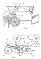
- the device for eliminating sheet curl according to the invention is inserted, for example, into an electrophoiographic copier 10, shown only partly in Fig. 1 for the sake of simplicity.
- the sheet emerging from the fixing rolls 18, 20 is passed through two rolls 24, 26 arranged downstream of the rolls 18, 20 at a certain distance D.
- the roll 24 is of rubber with a Shore hardness of approximately 60 and is rotated anticlockise in Fig. 2 by means of a kinematic transmission, not shown in the drawings, connected to the fixing roll 20 and to a main motor of the copier, also not shown for simplicity in the drawings.
- the roll 26 is covered with toner-repellent substance, for example Teflon (M.R.), to avoid sticking of the particles of toner of the images fixed on the sheet.
- toner-repellent substance for example Teflon (M.R.)
- the rolls 24 and 26 are arranged in such a manner that their nip 30 will lie in the half-plane limited by the common tangent T of the rolls 18, 20, on the further side with respect to the hot roll 20 and at a distance of not more than 2 mm from the tangent T.
- the nip 30 lies on the tangent T.
Landscapes
- Physics & Mathematics (AREA)
- General Physics & Mathematics (AREA)
- Fixing For Electrophotography (AREA)
- Separation, Sorting, Adjustment, Or Bending Of Sheets To Be Conveyed (AREA)
- Registering, Tensioning, Guiding Webs, And Rollers Therefor (AREA)
- Inspection Of Paper Currency And Valuable Securities (AREA)
- Paper Feeding For Electrophotography (AREA)
- Delivering By Means Of Belts And Rollers (AREA)
Description
- The present invention relates to a device for eliminating sheet curl and more particularly for eliminating sheet curl from sheets emerging from a hot fixing station in a copying machine or any similar image processing machine.
- It is well known, that in an electrophotographic copier the images to be reproduced are developed by means of particles of the toner and are then transferred to a sheet of paper.
- In order to fix the particles of toner to the paper, the sheets are passed through a fixing station, which works by heat and pressure, in which the particles of toner are softened and caused to penetrate into the paper, thereby fixing them stably to the paper.
- As a result of the effect of the heat and pressure, tensions are created within the thickness of the paper and the sheets of paper tend to curl. Subsequently, when deposited in a delivery tray, the sheets may retain this curl and in some cases a sheet may roll up on itself.
- From the Japanese published patent application no. 61-075369, a paper conveying device for a fixing station in which a pair of discharging rollers, positioned downstream of the fixing rollers, rotate faster than the fixing rollers is known. A paper sheet is tensioned on a curved surface of a guiding plate arranged between the discharging rollers and the fixing rollers so that the curl of the sheet is reduced.
- From the Japanese published patent application no. 57-009662 a similar anti-curling device in which the curved surface of a guiding plate is replaced by a squeezing roller for tensioning the paper sheet is known.
- From the Japanese published patent application no. 1-317950, a fixing device is known in which a pair of advancing rollers is arranged downstream of the fixing rolls and in order to reduce the sheet curl the advancing rollers are disposed on the side of the pressing roll, away from a line passing at the end point of the fixing nip and perpendicular to a center line passing through the center of the heating roller and the end point of the fixing nip.
- The US patent no. 4933726 shows a fixing device in which a pair of discharge rollers is located downstream of the fixing rolls. The discharge rollers have diameters so dimensioned that the sheets are discharged at a different speed at the center than at the edges to reduce the waving of the sheets.
- However, these devices fail to eliminate sheet curl altogether, and in fact with certain kinds of paper they can induce a curl in the opposite direction.
- A device for eliminating sheet curl is placed downstream of a fixing station in a photocopier, laser printer or the like. The device is formed from a pair of rolls which receive the sheets therebetween and apply tension to them in the direction of advance. The rolls forward the sheets in a direction out of line with the direction with which they leave the fixing station. Using such an arrangement sheet curl is eliminated and sheets are made perfectly flat.
- A pair of straightening rolls may be provided which define a nip which extends around the rolls. Sheets pass through this nip and are bent in an opposite direction to the natural direction of curl which they have on leaving the fixing station.
- The invention is defined in its various aspects in the appended claims to which reference should now be made.
- Embodiments of the invention will now be described in detail by way of example with reference to the accompanying drawings in which:
- Fig. 1 is a partial view of a copier using the device for eliminating sheet curl according to the invention;
- Fig. 2 is a view on an enlarged scale of the device of Fig. 1;
- Fig. 3 is a diagrammatic representation of a second embodiment of the device for eliminating sheet curl;
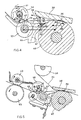
- Fig. 4 shows an enlarged detail of Fig. 3; and
- Fig. 5 shows another embodiment of the device of Fig. 3.
- With reference to Fig. 1, the device for eliminating sheet curl according to the invention is inserted, for example, into an
electrophoiographic copier 10, shown only partly in Fig. 1 for the sake of simplicity. - The sheets are held in a
cassette 12 from which they are taken one at a time by means of afriction roll 14, and are passed to a developing and transfer station ST, by means of a pair offorwarding rolls rolls roll 20 engages the sheet on the face carrying the toner image and it is covered with a layer of toner repellent material, for example Teflon (M.R.), and heated to a temperature of about 180°C to soften the particles of toner. - The
roll 18, opposite theroll 20, acts on the back of the sheet and is covered with a soft rubber layer and is pressed against theroll 20 with sufficient force to form an approximately 4 mm-wide nip between the two rolls. - When the sheet, carrying the toner image on the face nearest the
hot roll 20, is passed between the tworolls 18, 20 (Fig. 2), the combined action of the pressure and the heat causes the toner particles to soften and penetrate between the fibres of the sheet, so causing the image to adhere permanently to the sheet. - However, the effect of the heat and pressure combined together generates tensions within the thickness of the sheet, causing the sheet to curl. Consequently, on emerging from the fixing rolls, the unguided sheet would take a natural leaving
direction 21 inclining towards thehot roll 20, with respect to the common tangent T of the tworolls broken line 22. - To overcome this problem, the sheet emerging from the
fixing rolls rolls rolls - The
roll 24 is of rubber with a Shore hardness of approximately 60 and is rotated anticlockise in Fig. 2 by means of a kinematic transmission, not shown in the drawings, connected to thefixing roll 20 and to a main motor of the copier, also not shown for simplicity in the drawings. - The
roll 26 turns idly on a pin 27 and is pressed against theroll 24 by means of a spring 29 with a force which is typically of between 90 and 100 g. - The
roll 26 is covered with toner-repellent substance, for example Teflon (M.R.), to avoid sticking of the particles of toner of the images fixed on the sheet. - The
rolls nip 30 will lie in the half-plane limited by the common tangent T of therolls hot roll 20 and at a distance of not more than 2 mm from the tangent T. Preferably thenip 30 lies on the tangent T. - The arrangement makes it possible for the sheet to emerge from the fusing rolls in a direction inclining towards the
roll 18 by an angle of not less than 5° with respect to the natural direction ofemergence 21 of the sheet. - The operation of bending the sheet in the opposite direction to the natural curling adopted by the sheet as it emerges from the fixing rolls, is combined with a tension in the direction of advance.
- To this end the
roll 24 is rotated with a peripheral speed V′ 5-10% greater than the peripheral speed V of theroll 20. This creates a sliding of theroll 24 over the back of the sheet, from the front edge, until the rear edge leaves the nip of therolls - The operation of eliminating the curl is effective if applied to the sheet while the latter is still hot enough, or in other words within a characteristic predetermined time Tr of cooling of the sheet after it has left the
hot roll 20. - The cooling the Tr is the the in which the sheet emerging from the fixing rolls cools from the fixing temperature of around 140°C to a minimium temperature beneath which the combined action of straightening and tensioning applied by the
rolls - This condition will be satisfied by arranging the
rolls 24 and 26 a distance D from therolls hot roll 20. For the most commonly used types of paper and in normal conditions of ventilation of the machine, the time Tr is between 0.5 and 1.1 s, where the paper advances between the fixing rolls at a speed of between 35 mm/s and 60 mm/s. However, it is preferable for the distance D to be between 35 mm and 40 mm. - Fig. 3 shows another embodiment of the device for eliminating sheet curl according to the invention, in the case in which a belt-
type fixing station 32 is used. - In this known arrangement, an
endless belt 33 conveys the sheets in front of aflat heating element 35 fixed to aplate 38 positioned inside thebelt 33. The belt revolves around tworolls arrow 41. - The
element 35 is formed by, for example, a strip of electrically resistive material lying perpendicular to the plane of Fig.3 over the full transversal length of thesheet element 35 may be approximately 2 mm in width and is heated to approximately 230°C by applying to its ends an electrical current of suitable strength. Acounter-roll 42 of heat-resistant rubber is pressed against theouter surface 43 of thebelt 33 opposite theelement 35 is such a way as to form anip 44 between the roll and the belt extending in the direction perpendicular to the plane of figure 3 and having a width of not less than the width ofheating element 35 measured in the sense of thearrow 44. - The fixing of an
image 45 of toner deposited on one face of a sheet F takes place by heating theelement 35, which through thebelt 33 produces the softening of the toner particles, while the pressure applied by theroll 42 causes the toner to adhere to the sheet F. Sheets emerging from thenip 44 adopt a curl 47 (Fig. 4) which is concave on the side remote from theelement 35, so taking them away from theblet 33. The sheets tend to stay stuck to theroll 42 for a short distance, moving in a natural direction indicated by anarrow 49 in Fig. 4, pointing downwards. Thisnatural direction 49 forms with thetangent 48 to theroll 42 in the nip the belt 33 a variable angle φ of between 25° and 40° depending on the type of paper used. - To encourage the sheet to leave the roll 42 a
knife element 50 is provided (Fig.3), being hinged at thepoint 52 and pressed against theroll 42 by aspring 53. - A
guide 54 carries the sheet to the nip 56 between tworolls station 32. - The
lower roll 57 is covered with a soft rubber with a Shore hardness of between 25 and 40 and is kinematically connected in a known way not shown in the drawings to thedrive roll 39. - The
upper roll 58 turns idly and is covered with a layer of synthetic toner-repellent material whose Shore hardness of approximately 60-70 is greater than that of theroll 57. - The
upper roll 58 is pressed elastically by aspring 61 against theroll 57 with sufficient force to deform theroll 57 so as to form a nip 62 extending along the periphery of theroll 58 over an angle ϑ₁ of between 5° and 30° and preferably of 15°. - The shape of the
nip 62 is such as to impart to the sheet a curl in the opposite direction to thenatural curl 47, that is with its concavity turned towards theelement 35. - The
rolls belt 33, as a result of which the sheet emerging from the fixing station is kept taut by therolls - The
rolls station 32, so that the temperature of the sheet does not drop below the limit temperature, indicated above. It has been found that the distance D′ between thenip 62 and thenip 44 between theroll 42 and thebelt 33 should be not greater than 40 mm and preferably between 25 and 30 mm. - The
rolls nips natural direction 49 an angle φ₁ of between 5° and 20° and forming with the tangent 48 an angle φ₂ of not less than 10°. - Downstream of the
rolls rolls roll 58 over a further arc ϑ₂ following thenip 62, of between 10° and 45° and preferably of 30°. - The
roll 63 is connected kinematically in a known manner to theroll 57, while theroll 64 turns idly and is pressed elastically against theroll 63. Theroll 63 is rotated with a peripheral speed which is some 4% greater than the peripheral speed of therolls roll 58 along the arc ϑ₂. - Fig. 5 shows a variant of the device Fig. 3.
- For the sake of simplicity, in Fig. 5 the same reference numerals are kept for parts also appearing in Fig. 3.
- In Fig. 5 the
guide 54 has been omitted, and anextra roll 66 is arranged against theroll 58 after theroll 57 in the direction of movement of the sheet. Theroll 66 is pressed against theroll 58 by means of a spring 68 at a nip point C angularly distant by the angle ϑ₂ of Fig. 4 from thenip 62 between therolls - The purpose of a
roll 66 is to ensure that there is contact between the sheet and theroll 58 along the arc ϑ₂. - It will be understood that changes, additions or substitutions of parts may be made to the device for eliminating sheet curl, without thereby departing from the scope of the invention.
- Reference should be made to European Patent Application No. 94201435.8 which has been divided from the present application.
Claims (8)
- A device for eliminating the curl of sheets emerging from a fixing station (CF) of an image reproduction machine, the fixing station comprising a hot fixing roller (20) and an opposite pressure roller (18) for fixing images on sheets by pressure and heat, the sheets having a natural leaving direction (22) from the fixing station (CF) tending to bend toward the hot roller (20), a pair of rotatable straightening rollers (24,26) disposed downstream of the fixing station and forming a nip therebetween, to apply a tension to the sheets, characterised in that the straightening rollers are arranged from the fixing station by a distance D given by the relation:

- A device according to Claim 1 characterised in that the straightening rolls (24,26) are rotated with a peripheral speed approximately 10% greater than the speed at which the sheets emerge from the fixing station.
- A device according to any one of the preceding claims, characterised in that at least one of said straightening rolls is a drive roll (24) and that the second one (26) of the rolls turns idly, being pressed against the drive roll in order to apply the tension to the sheets.
- A device according to any one of Claims 1 to 3, characterised in that the fixing station comprises a flat heating element (35), and in that the straightening rolls form a first nip (62) between 5° and 30° wide, measured on the periphery of a first one (58) of the rolls.
- A device according to Claim 4, characterised in that the first nip is preferably 15° wide.
- A device according to Claims 4 or 5, characterised in that the sheets wrap around the first roll over a second area of contact of between 10° and 45° adjacent to the first nip.
- A device according to Claim 6, characterised by a further pair of drawing rolls (63,64) arranged downstream of the straightening rolls in such a way as to hold the sheets adhering to the second area of contact.
- A device according to Claim 7, characterised in that an extra straightening roll (66) is provided tangential to the first straightening roll the extra roll delimiting the second area of contact.
Priority Applications (1)
| Application Number | Priority Date | Filing Date | Title |
|---|---|---|---|
| EP94201435A EP0616264B1 (en) | 1990-11-06 | 1991-11-01 | Device for eliminating sheet curl |
Applications Claiming Priority (2)
| Application Number | Priority Date | Filing Date | Title |
|---|---|---|---|
| IT6786690 | 1990-11-06 | ||
| IT06786690A IT1247776B (en) | 1990-11-06 | 1990-11-06 | DEVICE TO CANCEL THE CURVATURE OF SHEETS |
Related Child Applications (1)
| Application Number | Title | Priority Date | Filing Date |
|---|---|---|---|
| EP94201435.8 Division-Into | 1994-05-20 |
Publications (3)
| Publication Number | Publication Date |
|---|---|
| EP0485123A2 EP0485123A2 (en) | 1992-05-13 |
| EP0485123A3 EP0485123A3 (en) | 1992-11-19 |
| EP0485123B1 true EP0485123B1 (en) | 1995-05-17 |
Family
ID=11305918
Family Applications (2)
| Application Number | Title | Priority Date | Filing Date |
|---|---|---|---|
| EP94201435A Expired - Lifetime EP0616264B1 (en) | 1990-11-06 | 1991-11-01 | Device for eliminating sheet curl |
| EP91310116A Expired - Lifetime EP0485123B1 (en) | 1990-11-06 | 1991-11-01 | Device for eliminating sheet curl |
Family Applications Before (1)
| Application Number | Title | Priority Date | Filing Date |
|---|---|---|---|
| EP94201435A Expired - Lifetime EP0616264B1 (en) | 1990-11-06 | 1991-11-01 | Device for eliminating sheet curl |
Country Status (5)
| Country | Link |
|---|---|
| US (1) | US5187527A (en) |
| EP (2) | EP0616264B1 (en) |
| JP (1) | JPH04341455A (en) |
| DE (2) | DE69124270T2 (en) |
| IT (1) | IT1247776B (en) |
Families Citing this family (26)
| Publication number | Priority date | Publication date | Assignee | Title |
|---|---|---|---|---|
| US5325164A (en) * | 1991-10-24 | 1994-06-28 | Konica Corporation | Fixing device with pulling rollers |
| JPH05181383A (en) * | 1991-10-29 | 1993-07-23 | Konica Corp | Fixing device |
| US5357327A (en) * | 1992-04-06 | 1994-10-18 | Xerox Corporation | Sheet decurling system including cross-curl |
| US5459560A (en) * | 1992-09-30 | 1995-10-17 | T/R Systems, Inc. | Buried electrode drum for an electrophotographic print engine with controlled resistivity layer |
| JP2500414B2 (en) * | 1992-12-11 | 1996-05-29 | 日本電気株式会社 | Paper feeding mechanism of electrophotographic device |
| JPH07160137A (en) * | 1993-12-01 | 1995-06-23 | Hitachi Ltd | Fixing device, fixing method, and recording device |
| US5623331A (en) * | 1994-05-27 | 1997-04-22 | Hitachi Koki Co., Ltd. | High-speed electrophotographic fixing unit |
| US5519481A (en) * | 1994-10-11 | 1996-05-21 | Xerox Corporation | Adaptive decurler for selective decurling of localized image areas |
| DE19654976C2 (en) * | 1995-05-09 | 2003-12-24 | Sharp Kk | Printing device for double-sided copies |
| US5749040A (en) * | 1995-07-20 | 1998-05-05 | Canon Kabushiki Kaisha | Image forming apparatus capable of correcting curl of sheet |
| US5961111A (en) * | 1996-10-29 | 1999-10-05 | Sharp Kabushiki Kaisha | Sheet feeding device for a duplex image forming apparatus |
| JPH10230654A (en) * | 1997-02-19 | 1998-09-02 | Alps Electric Co Ltd | Printer |
| JP3551683B2 (en) * | 1997-02-28 | 2004-08-11 | ブラザー工業株式会社 | Fixing device in image forming apparatus |
| US6160982A (en) * | 1999-10-04 | 2000-12-12 | Xerox Corporation | Copy sheet distortion-removing fusing apparatus |
| JP2003076182A (en) * | 2001-06-22 | 2003-03-14 | Ricoh Co Ltd | Fixing device and image forming device |
| JP3912127B2 (en) * | 2002-02-05 | 2007-05-09 | コニカミノルタホールディングス株式会社 | Image forming apparatus |
| JP2003295657A (en) * | 2002-04-04 | 2003-10-15 | Konica Corp | Fixing device |
| US7062218B2 (en) * | 2002-08-29 | 2006-06-13 | Xerox Corporation | Quad-roll decurler |
| US20050201786A1 (en) * | 2003-11-27 | 2005-09-15 | Takuya Ito | Sheet processing apparatus, automatic document feeder and image forming apparatus |
| JP4507882B2 (en) * | 2005-01-07 | 2010-07-21 | 船井電機株式会社 | Printer device |
| US8073371B2 (en) * | 2006-01-17 | 2011-12-06 | Ricoh Company, Ltd. | Image forming apparatus which corrects the curl of a discharge sheet |
| JP2008046168A (en) * | 2006-08-10 | 2008-02-28 | Canon Inc | Image forming apparatus |
| TWI397498B (en) * | 2010-11-24 | 2013-06-01 | Avision Inc | Sheet de-curling mechanism and printing apparatus using the same |
| JP6204275B2 (en) * | 2014-06-12 | 2017-09-27 | 京セラドキュメントソリューションズ株式会社 | Image forming apparatus |
| JP2016177085A (en) * | 2015-03-19 | 2016-10-06 | 株式会社リコー | Fixing device and image forming apparatus |
| JP2025136818A (en) * | 2024-03-08 | 2025-09-19 | 株式会社リコー | Fixing device and image forming apparatus |
Family Cites Families (16)
| Publication number | Priority date | Publication date | Assignee | Title |
|---|---|---|---|---|
| US4326915A (en) * | 1979-11-15 | 1982-04-27 | Xerox Corporation | Sheet de-curler |
| JPS6044217B2 (en) * | 1980-06-16 | 1985-10-02 | 松下電送株式会社 | Recording paper curl removal device |
| US4475896A (en) * | 1981-12-02 | 1984-10-09 | Xerox Corporation | Curling/decurling method and mechanism |
| US4505695A (en) * | 1983-04-18 | 1985-03-19 | Xerox Corporation | Sheet decurling mechanism |
| US4571054A (en) * | 1983-06-01 | 1986-02-18 | Xerox Corporation | Post-fuser copy sheet decurler |
| JPS6083978A (en) * | 1983-10-14 | 1985-05-13 | Toshiba Corp | Fixing device |
| US4652110A (en) * | 1984-02-29 | 1987-03-24 | Canon Kabushiki Kaisha | Image recording apparatus |
| US4632533A (en) * | 1985-04-01 | 1986-12-30 | Xerox Corporation | Off-set nip roll decurler |
| US4591259A (en) * | 1985-04-01 | 1986-05-27 | Xerox Corporation | Tri-pass baffle decurler |
| JPS61239274A (en) * | 1985-04-16 | 1986-10-24 | Minolta Camera Co Ltd | Fixing device |
| JPS6241768U (en) * | 1985-08-28 | 1987-03-12 | ||
| JP2565878B2 (en) * | 1986-10-16 | 1996-12-18 | 株式会社東芝 | Electronic copier |
| JPS63147765A (en) * | 1986-12-09 | 1988-06-20 | Canon Inc | Image forming device |
| JPS63276077A (en) * | 1987-05-07 | 1988-11-14 | Matsushita Electric Ind Co Ltd | Fixing device |
| EP0295901B1 (en) * | 1987-06-16 | 1995-12-20 | Canon Kabushiki Kaisha | An image fixing apparatus |
| JPH01317950A (en) * | 1988-06-16 | 1989-12-22 | Fuji Xerox Co Ltd | Fixing device for image formation device |
-
1990
- 1990-11-06 IT IT06786690A patent/IT1247776B/en active IP Right Grant
-
1991
- 1991-11-01 EP EP94201435A patent/EP0616264B1/en not_active Expired - Lifetime
- 1991-11-01 JP JP3287917A patent/JPH04341455A/en not_active Withdrawn
- 1991-11-01 DE DE69124270T patent/DE69124270T2/en not_active Expired - Lifetime
- 1991-11-01 DE DE69109809T patent/DE69109809T2/en not_active Expired - Lifetime
- 1991-11-01 EP EP91310116A patent/EP0485123B1/en not_active Expired - Lifetime
- 1991-11-06 US US07/788,357 patent/US5187527A/en not_active Expired - Lifetime
Also Published As
| Publication number | Publication date |
|---|---|
| IT9067866A0 (en) | 1990-11-06 |
| EP0616264A1 (en) | 1994-09-21 |
| DE69124270D1 (en) | 1997-02-27 |
| IT1247776B (en) | 1994-12-30 |
| EP0485123A3 (en) | 1992-11-19 |
| US5187527A (en) | 1993-02-16 |
| EP0616264B1 (en) | 1997-01-15 |
| DE69124270T2 (en) | 1997-06-19 |
| DE69109809D1 (en) | 1995-06-22 |
| IT9067866A1 (en) | 1992-05-06 |
| JPH04341455A (en) | 1992-11-27 |
| EP0485123A2 (en) | 1992-05-13 |
| DE69109809T2 (en) | 1995-10-05 |
Similar Documents
| Publication | Publication Date | Title |
|---|---|---|
| US5187527A (en) | Device for eliminating the curl of sheets emerging from a fixing station | |
| EP0395887B1 (en) | Conveying rotatable member and conveying apparatus | |
| JPH04204984A (en) | Heater | |
| JPH0684222B2 (en) | Sheet / curl removal mechanism | |
| JP2000143067A (en) | Sheet curl removing device | |
| JP2005234103A (en) | Fixing device | |
| JP4655822B2 (en) | Fixing apparatus and image forming apparatus | |
| JPH063900A (en) | Image forming device | |
| US5289244A (en) | Wrinkle prevention structure for electrophotographic printer | |
| JP3184022B2 (en) | Fixing device | |
| JP7642990B2 (en) | Fixing device | |
| US5258815A (en) | Fixing apparatus | |
| JPH0328438Y2 (en) | ||
| JP2958039B2 (en) | Jam prevention mechanism of heat roll fixing device | |
| JP3742181B2 (en) | Fixing device | |
| JP3627663B2 (en) | Fixing device | |
| JPH05257402A (en) | Fixing device for copying machine | |
| JPH1165192A (en) | Paper discharging device | |
| JP2001154519A (en) | Fixing device | |
| JPH08310704A (en) | Paper transferring device | |
| JPH03192382A (en) | Fixing device | |
| JPH0728352A (en) | Fixing device | |
| JP3085999B2 (en) | Fixing device | |
| JPH06289748A (en) | Fixing device | |
| JP3558939B2 (en) | Belt fixing device and image forming device |
Legal Events
| Date | Code | Title | Description |
|---|---|---|---|
| PUAI | Public reference made under article 153(3) epc to a published international application that has entered the european phase |
Free format text: ORIGINAL CODE: 0009012 |
|
| AK | Designated contracting states |
Kind code of ref document: A2 Designated state(s): DE FR GB NL |
|
| PUAL | Search report despatched |
Free format text: ORIGINAL CODE: 0009013 |
|
| AK | Designated contracting states |
Kind code of ref document: A3 Designated state(s): DE FR GB NL |
|
| 17P | Request for examination filed |
Effective date: 19921009 |
|
| R17P | Request for examination filed (corrected) |
Effective date: 19921029 |
|
| 17Q | First examination report despatched |
Effective date: 19931126 |
|
| GRAA | (expected) grant |
Free format text: ORIGINAL CODE: 0009210 |
|
| AK | Designated contracting states |
Kind code of ref document: B1 Designated state(s): DE FR GB NL |
|
| XX | Miscellaneous (additional remarks) |
Free format text: TEILANMELDUNG 94201435.8 EINGEREICHT AM 01/11/91. |
|
| REF | Corresponds to: |
Ref document number: 69109809 Country of ref document: DE Date of ref document: 19950622 |
|
| ET | Fr: translation filed | ||
| PLBE | No opposition filed within time limit |
Free format text: ORIGINAL CODE: 0009261 |
|
| STAA | Information on the status of an ep patent application or granted ep patent |
Free format text: STATUS: NO OPPOSITION FILED WITHIN TIME LIMIT |
|
| 26N | No opposition filed | ||
| REG | Reference to a national code |
Ref country code: GB Ref legal event code: IF02 |
|
| PGFP | Annual fee paid to national office [announced via postgrant information from national office to epo] |
Ref country code: NL Payment date: 20101123 Year of fee payment: 20 Ref country code: FR Payment date: 20101202 Year of fee payment: 20 |
|
| PGFP | Annual fee paid to national office [announced via postgrant information from national office to epo] |
Ref country code: DE Payment date: 20101126 Year of fee payment: 20 |
|
| PGFP | Annual fee paid to national office [announced via postgrant information from national office to epo] |
Ref country code: GB Payment date: 20101124 Year of fee payment: 20 |
|
| REG | Reference to a national code |
Ref country code: DE Ref legal event code: R071 Ref document number: 69109809 Country of ref document: DE |
|
| REG | Reference to a national code |
Ref country code: DE Ref legal event code: R071 Ref document number: 69109809 Country of ref document: DE |
|
| REG | Reference to a national code |
Ref country code: NL Ref legal event code: V4 Effective date: 20111101 |
|
| REG | Reference to a national code |
Ref country code: GB Ref legal event code: PE20 Expiry date: 20111031 |
|
| PG25 | Lapsed in a contracting state [announced via postgrant information from national office to epo] |
Ref country code: NL Free format text: LAPSE BECAUSE OF EXPIRATION OF PROTECTION Effective date: 20111101 |
|
| PG25 | Lapsed in a contracting state [announced via postgrant information from national office to epo] |
Ref country code: GB Free format text: LAPSE BECAUSE OF EXPIRATION OF PROTECTION Effective date: 20111031 |
|
| PG25 | Lapsed in a contracting state [announced via postgrant information from national office to epo] |
Ref country code: DE Free format text: LAPSE BECAUSE OF EXPIRATION OF PROTECTION Effective date: 20111102 |