JP2008046168A - Image forming apparatus - Google Patents
Image forming apparatus Download PDFInfo
- Publication number
- JP2008046168A JP2008046168A JP2006219009A JP2006219009A JP2008046168A JP 2008046168 A JP2008046168 A JP 2008046168A JP 2006219009 A JP2006219009 A JP 2006219009A JP 2006219009 A JP2006219009 A JP 2006219009A JP 2008046168 A JP2008046168 A JP 2008046168A
- Authority
- JP
- Japan
- Prior art keywords
- sheet
- roller
- fixing
- curl
- unit
- Prior art date
- Legal status (The legal status is an assumption and is not a legal conclusion. Google has not performed a legal analysis and makes no representation as to the accuracy of the status listed.)
- Pending
Links
Images


Classifications
-
- G—PHYSICS
- G03—PHOTOGRAPHY; CINEMATOGRAPHY; ANALOGOUS TECHNIQUES USING WAVES OTHER THAN OPTICAL WAVES; ELECTROGRAPHY; HOLOGRAPHY
- G03G—ELECTROGRAPHY; ELECTROPHOTOGRAPHY; MAGNETOGRAPHY
- G03G15/00—Apparatus for electrographic processes using a charge pattern
- G03G15/65—Apparatus which relate to the handling of copy material
- G03G15/6555—Handling of sheet copy material taking place in a specific part of the copy material feeding path
- G03G15/6573—Feeding path after the fixing point and up to the discharge tray or the finisher, e.g. special treatment of copy material to compensate for effects from the fixing
- G03G15/6576—Decurling of sheet material
-
- G—PHYSICS
- G03—PHOTOGRAPHY; CINEMATOGRAPHY; ANALOGOUS TECHNIQUES USING WAVES OTHER THAN OPTICAL WAVES; ELECTROGRAPHY; HOLOGRAPHY
- G03G—ELECTROGRAPHY; ELECTROPHOTOGRAPHY; MAGNETOGRAPHY
- G03G2215/00—Apparatus for electrophotographic processes
- G03G2215/00362—Apparatus for electrophotographic processes relating to the copy medium handling
- G03G2215/00535—Stable handling of copy medium
- G03G2215/00662—Decurling device
Abstract
Description
本発明は、画像形成装置に関し、特にシートに発生したカールを矯正するための構成に関するものである。 The present invention relates to an image forming apparatus, and more particularly to a configuration for correcting curl generated on a sheet.
従来、電子写真方式により画像を形成する複写機やプリンタ等の画像形成装置において、画像形成部で形成されたトナー像を給紙部から給送されたシートに転写し、この後、シートを定着部に導き、シート上の未定着トナーをシートに定着させるようにしている。 2. Description of the Related Art Conventionally, in an image forming apparatus such as a copying machine or a printer that forms an image by electrophotography, a toner image formed by an image forming unit is transferred to a sheet fed from a sheet feeding unit, and then the sheet is fixed. The unfixed toner on the sheet is fixed to the sheet.
このような定着部として、定着ローラと加圧ローラとを備え、定着ローラ及び加圧ローラによって熱と圧力を同時にシートに加えることによりトナー像をシートに定着させる熱圧定着方式の定着部がある。この定着部の場合、トナー像をシートに定着させる際、シートがカールすることがあり、このようにシートがカールした場合、搬送部においてジャム(紙詰まり)が発生するばかりでなく、排出トレイ上の積載能力を著しく低下させるおそれがある。 As such a fixing unit, there is a fixing unit of a hot-pressure fixing type that includes a fixing roller and a pressure roller, and fixes the toner image on the sheet by simultaneously applying heat and pressure to the sheet by the fixing roller and the pressure roller. . In the case of this fixing unit, when the toner image is fixed on the sheet, the sheet may be curled. When the sheet is curled in this way, not only a jam (paper jam) occurs in the conveying unit, but also on the discharge tray. There is a risk of significantly reducing the loading capacity.
シートがカールする現象は線膨張係数の異なる金属を2枚積載したバイメタルを加熱した場合と類似しており、またシートのカールはヒートカールと、トナーカールとに大別できる。 The phenomenon that the sheet curls is similar to the case where a bimetal on which two metals having different linear expansion coefficients are stacked is heated, and the sheet curl can be roughly divided into heat curl and toner curl.
ヒートカールは、シート内部の水分状態に応じて生じるものであり、特に定着直後のシートの表裏における水分差によって生じる。一般の定着部では、加熱源である定着ローラの表面温度と、加圧ローラの表面温度が異なるため、定着部を通過する際、シートの表裏において与えられる熱量が異なることから、シートの表裏における水分の吸湿・脱湿の遷移状態が異なる。 The heat curl is generated according to the moisture state inside the sheet, and is particularly caused by a moisture difference between the front and back of the sheet immediately after fixing. In a general fixing unit, since the surface temperature of the fixing roller as a heating source is different from the surface temperature of the pressure roller, the amount of heat given to the front and back of the sheet when passing through the fixing unit is different. Transition state of moisture absorption / dehumidification is different.
このように、表裏における水分の吸湿・脱湿の遷移状態が異なると、シートの繊維は吸湿すると膨張し、脱湿すると収縮することから、これに伴って繊維伸縮差が生じるためシートにカールが発生する。 In this way, if the moisture absorption and dehumidification transition states on the front and back sides are different, the fiber of the sheet expands when it absorbs moisture and contracts when it dehumidifies. appear.
トナーカールは、トナーの状態変化に応じて生じるものであり、特に定着後のトナーの膨張及び収縮と、シートの膨張及び収縮の差によって生じる。トナーの材質は樹脂成分が多いため、一般にはシート、例えば紙と、トナーの熱に対する膨張率を比較した場合、熱に対する膨張率はトナーの方が大きいため、温度変化に対する体積変化率もトナーの方が大きい。よって、定着後のシートは、シート自身が冷却されるにしたがって、温度変化に対する体積変化率の相違から、体積変化率の大きいトナー層側が縮むようになり、これによりカールが発生する。 Toner curl is generated according to a change in the state of the toner, and is particularly caused by the difference between the expansion and contraction of the toner after fixing and the expansion and contraction of the sheet. Since the toner material has a large amount of resin component, in general, when comparing the thermal expansion coefficient of the toner with a sheet, for example, paper, the thermal expansion coefficient of the toner is larger. Is bigger. Therefore, as the sheet itself is cooled, the toner layer side having a large volume change rate contracts due to the difference in the volume change rate with respect to the temperature change, thereby causing curling.
そこで、従来のシート搬送装置及び画像形成装置においては、シートに対し、シートに発生したカールと逆方向にカール付けするカール矯正部を設け、このカール矯正部によりシートのカールを矯正(補正)するようにしている(例えば、特許文献1参照)。 Therefore, in the conventional sheet conveying apparatus and image forming apparatus, a curl correction unit for curling the sheet in a direction opposite to the curl generated on the sheet is provided, and the curl correction unit corrects (corrects) the curl of the sheet. (For example, refer to Patent Document 1).
図7は、このような従来のカール矯正部の構成を示す図である。このカール矯正部は、定着部よりもシート搬送方向下流側に設けられ、硬度が異なる2本のカール矯正ローラ203a,203b、即ち金属ローラ203bと、金属ローラ203bに接離可能に圧接するスポンジローラ203cとを備えている。
FIG. 7 is a diagram showing the configuration of such a conventional curl correction unit. The curl correction unit is provided downstream of the fixing unit in the sheet conveyance direction, and has two
金属ローラ203bは、駆動入力ギア201を介して伝達される不図示の駆動源の駆動により回転するようになっている。スポンジローラ203cは、軸支部206により金属ローラ203bに対して接離可能に保持されると共に、発泡シリコンゴムにより形成されるローラ部203aを備えている。
The
このスポンジローラ203cは、軸203dの両端に設けた加圧バネ205により、金属ローラ203bとの間で金属ローラ203bが食い込む形の所望のニップが形成されるように圧接されている。なお、このニップの形状は、シートのカール方向と逆方向となる。また、スポンジローラ203cへの駆動伝達は、金属ローラ203bと、金属ローラ203bが食い込んだ状態のローラ部203aとの間の摩擦力のみで行われる。
The
そして、このようにカール矯正部を構成することにより、画像定着後、シートがローラ間を通過する際に、シートにカール方向と逆方向に反るくせをつけることができ、これによりシートのカールが矯正される。 By configuring the curl correction unit in this way, the sheet can be warped in the direction opposite to the curl direction when the sheet passes between the rollers after the image is fixed. Is corrected.
しかし、このような従来のカール矯正部は定着部のシート搬送方向下流側に設けられているが、定着部からの距離が長くなるほど、定着部により加熱されたシートが冷却されてカール矯正部に達するようになる。 However, such a conventional curl correction unit is provided on the downstream side of the fixing unit in the sheet conveyance direction. However, as the distance from the fixing unit becomes longer, the sheet heated by the fixing unit is cooled and becomes a curl correction unit. To reach.
このようにシートが冷却されて達すると、カール矯正効果が低下することから、定着部からの距離が長くなる場合には、カールを確実に矯正するためカール矯正部の2本のローラ203a,203bのニップ圧を高くする必要がある。しかし、ニップ圧を高くした場合、消費電力の増加を招くばかりでなく、金属ローラ203bを駆動するための機構の強度を上げなくてはならず、さらに耐久劣化が早まるという問題がある。
Since the curl correction effect is reduced when the sheet is cooled in this way, when the distance from the fixing unit becomes long, the two
また、シートを搬送する場合、2本のローラ203a,203bの表面温度がシートの温度より低いとシートを冷却してしまい、カール矯正効果を低下させるおそれがある。特に、近年開発されている、熱容量を小さくすることでスタンバイレス、あるいは低スタンバイ電力を実現した省エネ定着部においては、プリントジョブが開始されるまではカール矯正部を含む定着部周辺の構造体が温まっていない。
Further, when the sheet is conveyed, if the surface temperature of the two
この状態からプリントジョブが開始されると、シートが到達するまでにカール矯正部が温まっていない場合には、シートの温度低下をもたらし、これに伴い既述したようにカール矯正効果が低下する。 When the print job is started from this state, if the curl correcting portion is not warmed until the sheet arrives, the temperature of the sheet is lowered, and as a result, the curl correcting effect is lowered as described above.
このように、シートが冷却してカール矯正部に達した場合、あるいはカール矯正部においてシートの温度が低下した場合、シートのカールを効率的、安定的に矯正することができない。 As described above, when the sheet cools and reaches the curl correction unit, or when the temperature of the sheet decreases in the curl correction unit, the curl of the sheet cannot be corrected efficiently and stably.
そこで、本発明は、このような現状に鑑みてなされたものであり、シートのカールを効率的、安定的に矯正することのできる画像形成装置を提供することを目的とするものである。 Accordingly, the present invention has been made in view of such a current situation, and an object of the present invention is to provide an image forming apparatus capable of correcting a curl of a sheet efficiently and stably.
本発明は、シートに転写されたトナー像を加熱及び加圧してシートに定着させる定着部の下流側に設けられ、シートを搬送しながらシートのカールを矯正するカール矯正部を備えた画像形成装置において、前記カール矯正部は、シートを搬送しながらシートのカールを矯正するローラ対を備え、前記ローラ対は、弾性部材により形成されるローラ部を有する第1のローラと、前記第1のローラのローラ部よりも硬度が高く、中空形状に形成された第2のローラとから構成されていることを特徴とするものである。 The present invention provides an image forming apparatus provided with a curl correction unit that is provided on the downstream side of a fixing unit that heats and pressurizes a toner image transferred to a sheet and fixes the toner image on the sheet, and corrects the curl of the sheet while conveying the sheet. The curl correcting unit includes a roller pair that corrects the curl of the sheet while conveying the sheet, and the roller pair includes a first roller having a roller unit formed by an elastic member, and the first roller. It is characterized in that it is composed of a second roller having a higher hardness than the roller portion and formed in a hollow shape.
本発明のように、カールを矯正するカール矯正部のローラ対を、弾性部材のローラ部を有するローラと中空形状のローラとで構成したため、ローラ対が定着部の熱により温まると共に温まった状態を維持することができる。これにより、シートのカールを効率的、安定的に矯正することができる。 As in the present invention, since the roller pair of the curl correction unit that corrects the curl is composed of a roller having a roller part of an elastic member and a hollow roller, the roller pair is heated and heated by the heat of the fixing unit. Can be maintained. Thereby, the curl of the sheet can be corrected efficiently and stably.
以下、本発明を実施するための最良の形態について図面を用いて詳細に説明する。 The best mode for carrying out the present invention will be described below in detail with reference to the drawings.
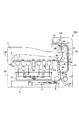
図1は、本発明の実施の形態に係る画像形成装置の構成を示す図である。100は画像形成装置、101は画像形成装置本体(以下、装置本体という)、102はシートに画像を形成する画像形成部、5は定着部である。
FIG. 1 is a diagram showing a configuration of an image forming apparatus according to an embodiment of the present invention.
ここで、画像形成部102は、イエロー、マゼンタ、シアン及びブラックの4色のトナー画像を形成する感光体ドラムa〜dと、画像情報に基づいてレーザビームを照射して感光体ドラム上に静電潜像を形成する露光装置6等を備えている。なお、この感光体ドラムa〜dは不図示のモータにより駆動されると共に、周囲には、それぞれ不図示の一次帯電器、現像器、転写帯電器が配置されており、これらはプロセスカートリッジ1a〜1dとしてユニット化されている。
Here, the
2は、矢印方向に回転駆動される中間転写ベルトであり、この中間転写ベルト2に転写帯電器2a〜2dによって転写バイアスを印加することにより、感光体ドラム上の各色トナー像が順次中間転写ベルト2に多重転写される。これにより、中間転写ベルト上にはフルカラー画像が形成される。
Reference numeral 2 denotes an intermediate transfer belt that is rotationally driven in the direction of an arrow. By applying a transfer bias to the intermediate transfer belt 2 by
3は、順次中間転写ベルト2に形成されたフルカラー画像をシートPに転写する2次転写部、103は定着部5の下流に設けられ、定着部5により画像が定着されたシートPを搬送するシート搬送装置である。このシート搬送装置103は、定着部5により画像が定着されたシートPを排紙トレイ7に排出する排出部を構成する排出ローラ対11と、定着部5の下流に設けられたカール矯正部70とを備えている。
3 is a secondary transfer unit that sequentially transfers the full color image formed on the intermediate transfer belt 2 to the sheet P, and 103 is provided downstream of the
次に、このように構成された画像形成装置100の画像形成動作について説明する。
Next, an image forming operation of the
画像形成動作が開始されると、まず不図示のパソコン等からの画像情報に基づき露光装置6はレーザ光を照射し、表面が所定の極性・電位に一様に帯電されている感光ドラムa〜dの表面を順次露光して感光ドラムa〜dに静電潜像を形成する。この後、この静電潜像をトナーにより現像し、可視化する。 When the image forming operation is started, first, the exposure device 6 irradiates a laser beam based on image information from a personal computer (not shown), and the photosensitive drum a to which the surface is uniformly charged to a predetermined polarity and potential. The surface of d is sequentially exposed to form electrostatic latent images on the photosensitive drums a to d. Thereafter, the electrostatic latent image is developed with toner and visualized.
例えば、まず感光ドラムaに、原稿のイエロー成分色の画像信号によるレーザ光を露光装置6のポリゴンミラー等を介して照射し、感光ドラムa上にイエローの静電潜像を形成する。そして、このイエローの静電潜像を、現像器からのイエロートナーにより現像し、イエロートナー像として可視化する。 For example, first, laser light based on a yellow component color image signal of an original is irradiated onto the photosensitive drum a through a polygon mirror of the exposure device 6 to form a yellow electrostatic latent image on the photosensitive drum a. The yellow electrostatic latent image is developed with yellow toner from a developing device and visualized as a yellow toner image.
次に、このトナー像が感光ドラムaの回転に伴って感光ドラムaと中間転写ベルト2とが当接する1次転写部に到来すると、転写帯電器2aに印加した1次転写バイアスにより、感光ドラムa上のイエロートナー像が中間転写ベルト2に転写される(1次転写)。
Next, when the toner image arrives at the primary transfer portion where the photosensitive drum a and the intermediate transfer belt 2 come into contact with the rotation of the photosensitive drum a, the photosensitive drum is driven by the primary transfer bias applied to the
次に、中間転写ベルト2のイエロートナー像を担持した部位が移動すると、このときまでに上記と同様な方法で感光体ドラムb上に形成されたマゼンタトナー像がイエロートナー像上から中間転写ベルト2に転写される。同様に、中間転写ベルト2が移動するにつれて、それぞれ1次転写部においてシアントナー像、ブラックトナー像が、イエロートナー像、マゼンタトナー像上に重ね合わせて転写される。これにより、中間転写ベルト2上にフルカラートナー画像が形成される。 Next, when the portion of the intermediate transfer belt 2 carrying the yellow toner image moves, the magenta toner image formed on the photosensitive drum b by the same method as described above is transferred from the yellow toner image to the intermediate transfer belt. 2 is transferred. Similarly, as the intermediate transfer belt 2 moves, a cyan toner image and a black toner image are superimposed and transferred onto the yellow toner image and the magenta toner image in the primary transfer portion, respectively. As a result, a full-color toner image is formed on the intermediate transfer belt 2.
また、このトナー画像形成動作に並行して給紙カセット4に収容されたシートPは、ピックアップローラ8により1枚ずつ送り出されてレジストローラ9に達し、このレジストローラ9によりタイミングを合わされた後、2次転写部3に搬送される。そして、この2次転写部3において、転写手段である2次転写ローラ3aに印加される2次転写バイアスによって中間転写ベルト2上の4色のトナー像がシートP上に一括して転写される(2次転写)。
Further, in parallel with the toner image forming operation, the sheets P accommodated in the paper feed cassette 4 are sent one by one by the
次に、トナー像が転写されたシートPは、2次転写部3〜定着ローラ対5の間に設けられた搬送ガイド40に案内されて定着部5に搬送される。そして、この定着部5により、熱及び圧力を受けて各色のトナーが溶融混色し、シートPにフルカラーの画像として定着される。
Next, the sheet P on which the toner image has been transferred is guided to a
この後、このように画像が定着されたシートPは、定着部5の下流に設けられたカール矯正部70によりカールが矯正された後、排出ローラ対11によって排紙トレイ7に排紙される。
Thereafter, the sheet P on which the image has been fixed in this manner is curled by a
なお、この画像形成装置100は、両面画像形成が可能であり、両面画像形成時には、排出ローラ対11の反転と切換フラッパ46の切替えによりシートPは両面搬送路47へと搬送される。この後、シートPは、合流部48を経由してレジストローラ9へと再給紙され、1面目の画像形成時と同様に上記の画像形成動作によりトナー画像が形成される。
The
本実施の形態において、定着部は、スタンバイレスを実現した省エネ定着部であり、また定着ベルト加熱方式、加圧用回転体駆動方式(テンションレスタイプ)の定着部である。この定着部は、図2に示すように、ベルト状部材に弾性層を設けてなる円筒状(エンドレスベルト状、スリーブ状)の部材である定着ベルト20と、定着ベルト20と圧接する加圧ローラ22とを備えている。
In the present embodiment, the fixing unit is an energy-saving fixing unit that realizes standby-less, and is a fixing unit that uses a fixing belt heating method and a pressing rotary member driving method (tensionless type). As shown in FIG. 2, the fixing unit includes a fixing
なお、図2において、17は加熱体保持部材としての、横断面略半円弧状樋型の耐熱性、剛性を有するヒータホルダ、16は加熱体(熱源)としての定着ヒータであり、ヒータホルダ17の下面にヒータホルダ17の長手に沿って配設されている。定着ベルト20は、このヒータホルダ17にルーズに外嵌させてあり、図3に示すように定着フランジ50に端部を付勢された状態で装置フレーム24に取り付けられている。
In FIG. 2,
23は装置フレーム24に組付けられた入口ガイドであり、この入口ガイド23により二次転写部3を抜けたシートPは定着ヒータ16の配設位置に対応する定着ベルト20と加圧ローラ22との圧接部である定着ニップ部27に正確にガイドされる。
加圧ローラ22は、ステンレス製の芯金22aに、射出成形により厚み約3mmのシリコンゴムによりなる弾性層22bを形成し、その上に厚み約40μmのPFA樹脂チューブを被覆して形成されている。この加圧ローラ22は装置フレーム24の不図示の奥側と手前側の側板間に、芯金22aの両端部を回転自由に保持された状態で配設されている。
The
この加圧ローラ22の上側に定着ヒータ16、ヒータホルダ17、定着ベルト20等から成る定着ベルトユニット20Aが定着ヒータ16側を下向きにして加圧ローラ22に並行に配置されている。
A fixing
なお、本実施の形態において、ヒータホルダ17の両端部は不図示の加圧機構により片側98N、総圧196Nの力で加圧ローラ22の軸線方向に付勢されている。これにより、定着ヒータ16の下向き面を、定着ベルト20を介して加圧ローラ22の弾性層22bに、弾性層22bの弾性に抗して所定の押圧力をもって圧接させ、加熱定着に必要な所定幅の定着ニップ部27を形成することができる。なお、加圧機構は、圧解除機構を有しており、ジャム処理時等には、この圧解除機構によって加圧ローラ22の加圧を解除することにより、シートPの除去を容易に行うことができるようになっている。
In the present embodiment, both ends of the
加圧ローラ22は、不図示の駆動手段により図2に示す矢印方向に所定の周速度で回転駆動される。そして、定着ニップ部27における加圧ローラ22の回転による加圧ローラ22の外面と定着ベルト20との圧接摩擦力により、定着ベルト20に回転力が作用する。
The
この結果、定着ベルト20は、その内面側が定着ヒータ16の下向き面に密着して摺動しながら、ヒータホルダ17の外回りを矢印方向に従動回転する。なお、定着ベルト20内面にはグリスが塗布されており、このグリスによりヒータホルダ17と定着ベルト20内面との摺動性を確保している。
As a result, the fixing
この後、このように加圧ローラ22の回転駆動に伴って定着ベルト20が従動回転した状態で定着ヒータ16に通電がなされ、定着ベルト20の表面温度が180℃になるように温度調整がなされる。このような定着ベルト20の温度調整がなされた後、未定着トナー像tを担持したシートPが、入口ガイド23に沿って定着ベルト20と加圧ローラ22との間の定着ニップ部27に導入される。この定着ニップ部27において、シートPは、トナー像担持面側が定着ベルト20の外面に密着した状態で定着ベルト20と一緒に定着ニップ部27を挟持搬送されていく。
Thereafter, the fixing
この挟持搬送過程において、定着ヒータ16の熱が定着ベルト20を介してシートPに付与され、これによりシートP上の未定着トナー像tが加熱・加圧されてシートP上に溶融定着される。この後、定着ニップ部27を通過したシートPは定着ベルト20から曲率分離されて排出される。
In this nipping and conveying process, the heat of the fixing
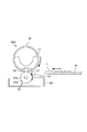
カール矯正部70は、図4に示すように第1のローラであるスポンジローラ71と、第2のローラである中空ローラ72とから構成されている。スポンジローラ71は、直径6mmの金属軸71bと、金属軸上に形成された直径9mmの弾性部材である発泡シリコンゴムから成るスポンジ状のローラ部71aとを有している。
As shown in FIG. 4, the
中空ローラ72は、スポンジローラ71のローラ部71aよりもはるかに硬度の高いステンレスやアルミなどの金属により外径直径9mm、肉厚0.45mmで形成されたものである。なお、本実施の形態では、スポンジローラ71及び中空ローラ72へのトナー付着を防ぐため、それぞれのローラ71,72の表面をPTFE,PFA等の厚さ0.1mm程度の薄いフッ素チューブ層71c,72cにより被覆している。
The
中空ローラ72は、図5に示すように軸長手方向両端が焼結軸受73を介して不図示の側板に支持されると共に、不図示の駆動源からの駆動によりシート搬送方向に回転駆動される。スポンジローラ71の軸長手方向両端は、すべり軸受78を介して保持部材77に形成されたスリット77aにより中空ローラ72に向かって移動可能に保持されている。
As shown in FIG. 5, both ends of the
なお、本実施の形態において、スポンジローラ71と中空ローラ72とは、例えば加圧バネ79によって片側2.5N、即ち総圧5Nで加圧されている。このような加圧により、図6に示すように、スポンジローラ71と中空ローラ72(のローラ部71a)との間で、中空ローラ72がスポンジローラ71に食い込む形の所望のニップが形成される。なお、このニップの形状は、シートのカール方向と逆方向となる。
In the present embodiment, the
ここで、カール矯正部70によるカール矯正効果は、スポンジローラ71、中空ローラ72間の加圧力(力学的エネルギー)の他、シートの温度状態(熱エネルギー)にも依存する。一般には、力学的エネルギーの観点からは加圧力が低いほどカール矯正効果が低下し、熱エネルギーの観点からは、定着部5から遠いほどシートPの温度が低下し、カール矯正効果が低下してしまう。
Here, the curl correction effect by the
また、本実施の形態のような省エネの定着部5を用いた場合にはスタンバイ状態がないことから、プリントジョブが開始される前は、定着部5及びカール矯正部70を含む周辺の構造体が温まっていないコールド状態となっている。このため、コールド状態からプリントジョブが開始された場合、既述したようにシートPがカール矯正部70に到達するまでにカール矯正部70が温まっていないと、シートPの温度低下をもたらし、シートPへのカール矯正効果が低減する。
In addition, when the energy-saving
この場合、連続枚数プリントした場合に1枚目のシートのカール状態と、最終枚のシートのカール状態が著しく異なるため、安定したカール状態のシートPの出力ができなくなる。このため、定着部5が、定着ヒータ16によって所定の温度に立ち上げ温調されるのと同時に、カール矯正部70も温まると共に、温まった状態を維持するようにすることが必要である。
In this case, when the continuous number of sheets is printed, the curl state of the first sheet and the curl state of the final sheet are remarkably different, so that the sheet P in a stable curl state cannot be output. For this reason, it is necessary for the fixing
そこで、本実施の形態では、カール矯正部70を、既述したように熱伝導率が小さいスポンジ状のローラ部71aを有するスポンジローラ71と、スポンジローラ71の表面よりも表面硬度が高く、熱容量が小さい金属の中空ローラ72で構成している。中空ローラ72は熱容量が小さいため、定着部5から発生した熱を吸熱したのち、速やかに昇温する。また、このように昇温した中空ローラ72により、スポンジローラ71も加熱される。
Therefore, in the present embodiment, the
スポンジローラ71はローラ部71aを熱伝導率が小さいスポンジにより形成することにより、表層の熱が逃げにくくしているため、定着部5から発生した後、中空ローラ72を介して伝わった熱によって温まったスポンジローラ71の表層温度が維持しやすい。
The
また、カール矯正部70を定着部5の近傍、例えば定着部5と排出ローラ対11の間に配置している。なお、本実施の形態では、カール矯正部70を、定着部5とのニップ中心間距離が30mmとなるように配置している。
Further, the
このようにカール矯正部70を配置することにより、両面プリント時にも1面目と2面目の双方が、定着部5から発生した熱により温められているカール矯正部70を通過することから、両面プリント時にも安定したカール矯正が可能となる。また、シートP自身の温度も高いことから、一層のカール矯正効果が期待できる。
By arranging the
次に、このように構成されたカール矯正部70のカール矯正動作について説明する。
Next, the curl correcting operation of the
コールド状態からのジョブが開始されると、既述したように感光ドラムa〜dにトナー像が形成された後、トナー像が中間転写ベルト2を介してシートPに転写され、この後、転写されたトナー像は定着部5においてシートPに定着される。
When a job from the cold state is started, a toner image is formed on the photosensitive drums a to d as described above, and then the toner image is transferred to the sheet P via the intermediate transfer belt 2. The toner image thus fixed is fixed on the sheet P in the fixing
このとき、カール矯正部70が定着部5の近傍に配置されていることから、また中空ローラ72が熱伝導率の良い金属製であることから、定着部5から発生する熱を効率よく伝達されて、カール矯正部70の表層温度も急速に上昇させることができる。
At this time, since the
これにより、トナー像が定着されたシートPが、図6に示すようにカール矯正部70のニップに進入すると、シートPは中空ローラ72がスポンジローラ71に食い込む形のニップ形状にならって搬送され、この際、シートPは周方向にカール付けされる。この周方向のカール付けにより、シートPのカールが矯正される。
As a result, when the sheet P on which the toner image is fixed enters the nip of the
このように、カール矯正部70のローラ対71,72を、スポンジローラ71と、熱容量が小さい金属の中空ローラ72で構成することにより、短時間でカール矯正部70を温ためることができると共に、温まった状態を維持することができる。これにより、シートのカールを効率的、安定的に矯正することができる。
Thus, by configuring the
また、カール矯正部70を定着部5の近傍に設けることにより、定着部5を通過したシートPが冷えることなく、また効率よく定着部5から発生する熱を利用できるため、カール矯正部70の加圧力を高くする必要もなくなり、省電力化・高寿命化を実現できる。
In addition, by providing the
なお、これまでの説明においては、非画像面側にスポンジローラ71、画像面側に中空ローラ72を配置したが、これら2つのローラ71,72の配置は、シートのカール方向に応じて逆にしてもよい。
In the above description, the
また、スポンジローラ71、中空ローラ72の外径、形状、カール矯正部70の定着部5からの距離等は、既述したものに限らない。例えば、カール矯正部70の寿命あるいは画像形成装置より与えられる電力、コールド状態からのジョブ開始において、定着部5から発生する熱量によるカール矯正部70の表面温度の所定温度への上昇等の設計条件に応じて決定すればよい。
Further, the outer diameter and shape of the
さらに、本実施の形態において、定着部5は省エネの定着部5を用いたが、スタンバイ加熱のある一般の熱ローラ定着部等を用いても定着部5から発生する熱エネルギーを効率的に利用可能となる。
Further, in the present embodiment, the fixing
また、本実施の形態では、定着部5と排出ローラ対11の間にカール矯正部70を配置したが、シートPを機外に排出する排出ローラ対11の機能をカール矯正部70に持たせてもよい。つまり、排出ローラ対11の代わりにカール矯正部70により、シートを排出するように構成しても良い。
In this embodiment, the
さらに、本実施の形態のカール矯正部70は、表面温度を短時間で上昇させることができるため、冷えた状態のカール矯正部70に定着直後、シートPから発生する水分(水蒸気)が当ることによってカール矯正部70の表層に発生する結露を防ぐことができる。
Further, since the
即ち、本実施の形態のカール矯正部70は、表面温度を短時間で上昇させることができるため、定着直後、シートPから発生した水蒸気は、カール矯正部周辺では水蒸気のまま維持され、コールド状態からの立ち上がりにおいても結露を防止することが可能となる。これにより、両面プリント時、結露によるシートの濡れによる転写ムラ(画像ムラ)の発生を抑えることができる。
That is, since the
2 中間転写ベルト
5 定着部
11 排出ローラ対
70 カール矯正部
71 スポンジローラ
71a ローラ部
72 中空ローラ
100 画像形成装置
102 画像形成部
103 シート搬送装置
P シート
2
Claims (5)
前記カール矯正部は、シートを搬送しながらシートのカールを矯正するローラ対を備え、
前記ローラ対は、弾性部材により形成されるローラ部を有する第1のローラと、前記第1のローラのローラ部よりも硬度が高く、中空形状に形成された第2のローラとから構成されていることを特徴とする画像形成装置。 In an image forming apparatus provided with a curl correction unit that is provided downstream of a fixing unit that heats and pressurizes a toner image transferred to a sheet and fixes the toner image on the sheet, and corrects the curl of the sheet while conveying the sheet.
The curl correction unit includes a roller pair for correcting the curl of the sheet while conveying the sheet,
The roller pair includes a first roller having a roller portion formed by an elastic member, and a second roller having a higher hardness than the roller portion of the first roller and formed in a hollow shape. An image forming apparatus.
前記カール矯正部を、前記定着部と前記排紙部との間に設けたことを特徴とする請求項1ないし3のいずれか1項に記載の画像形成装置。 A paper discharge unit that is disposed downstream of the fixing unit and discharges the sheet;
The image forming apparatus according to claim 1, wherein the curl correction unit is provided between the fixing unit and the paper discharge unit.
The image forming apparatus according to claim 1, wherein the curl correcting unit discharges the sheet onto a discharge tray outside the apparatus.
Priority Applications (3)
| Application Number | Priority Date | Filing Date | Title |
|---|---|---|---|
| JP2006219009A JP2008046168A (en) | 2006-08-10 | 2006-08-10 | Image forming apparatus |
| US11/835,351 US20080038031A1 (en) | 2006-08-10 | 2007-08-07 | Image forming apparatus |
| CNB2007101408770A CN100573348C (en) | 2006-08-10 | 2007-08-10 | Imaging device |
Applications Claiming Priority (1)
| Application Number | Priority Date | Filing Date | Title |
|---|---|---|---|
| JP2006219009A JP2008046168A (en) | 2006-08-10 | 2006-08-10 | Image forming apparatus |
Publications (2)
| Publication Number | Publication Date |
|---|---|
| JP2008046168A true JP2008046168A (en) | 2008-02-28 |
| JP2008046168A5 JP2008046168A5 (en) | 2009-10-08 |
Family
ID=39050940
Family Applications (1)
| Application Number | Title | Priority Date | Filing Date |
|---|---|---|---|
| JP2006219009A Pending JP2008046168A (en) | 2006-08-10 | 2006-08-10 | Image forming apparatus |
Country Status (3)
| Country | Link |
|---|---|
| US (1) | US20080038031A1 (en) |
| JP (1) | JP2008046168A (en) |
| CN (1) | CN100573348C (en) |
Cited By (3)
| Publication number | Priority date | Publication date | Assignee | Title |
|---|---|---|---|---|
| JP2016173500A (en) * | 2015-03-17 | 2016-09-29 | 株式会社リコー | Image forming apparatus |
| JP2016177082A (en) * | 2015-03-19 | 2016-10-06 | 株式会社リコー | Fixing exit guide plate, fixing device and image formation apparatus |
| JP2017026811A (en) * | 2015-07-22 | 2017-02-02 | 株式会社リコー | Image forming apparatus |
Families Citing this family (4)
| Publication number | Priority date | Publication date | Assignee | Title |
|---|---|---|---|---|
| KR101435946B1 (en) * | 2008-12-04 | 2014-09-01 | 삼성전자 주식회사 | Laser Scanning Unit And Image Forming Apparatus Having The Same |
| CN103317859A (en) * | 2012-03-19 | 2013-09-25 | 中国计量学院 | Method for neatening printing paper |
| JP6079106B2 (en) * | 2012-10-01 | 2017-02-15 | セイコーエプソン株式会社 | Liquid ejector |
| US9811043B2 (en) * | 2015-03-17 | 2017-11-07 | Ricoh Company, Ltd. | Image forming apparatus |
Citations (3)
| Publication number | Priority date | Publication date | Assignee | Title |
|---|---|---|---|---|
| JPH04322278A (en) * | 1991-04-22 | 1992-11-12 | Canon Inc | Image forming device |
| JPH04341455A (en) * | 1990-11-06 | 1992-11-27 | Olivetti Canon Ind Spa | Device for removing curl of paper |
| JP2000226149A (en) * | 1999-02-04 | 2000-08-15 | Fuji Xerox Co Ltd | Image forming device |
Family Cites Families (5)
| Publication number | Priority date | Publication date | Assignee | Title |
|---|---|---|---|---|
| JP2500414B2 (en) * | 1992-12-11 | 1996-05-29 | 日本電気株式会社 | Paper feeding mechanism of electrophotographic device |
| US5787331A (en) * | 1994-12-14 | 1998-07-28 | Canon Kabushiki Kaisha | Curl correction device of an image forming apparatus |
| US6965750B2 (en) * | 2003-10-21 | 2005-11-15 | Kabushiki Kaisha Toshiba | Image forming apparatus |
| JP4474295B2 (en) * | 2004-04-26 | 2010-06-02 | キヤノン株式会社 | Image forming apparatus |
| JP4438071B2 (en) * | 2004-07-20 | 2010-03-24 | キヤノン株式会社 | Sheet processing apparatus and image forming apparatus provided with the apparatus |
-
2006
- 2006-08-10 JP JP2006219009A patent/JP2008046168A/en active Pending
-
2007
- 2007-08-07 US US11/835,351 patent/US20080038031A1/en not_active Abandoned
- 2007-08-10 CN CNB2007101408770A patent/CN100573348C/en active Active
Patent Citations (3)
| Publication number | Priority date | Publication date | Assignee | Title |
|---|---|---|---|---|
| JPH04341455A (en) * | 1990-11-06 | 1992-11-27 | Olivetti Canon Ind Spa | Device for removing curl of paper |
| JPH04322278A (en) * | 1991-04-22 | 1992-11-12 | Canon Inc | Image forming device |
| JP2000226149A (en) * | 1999-02-04 | 2000-08-15 | Fuji Xerox Co Ltd | Image forming device |
Cited By (3)
| Publication number | Priority date | Publication date | Assignee | Title |
|---|---|---|---|---|
| JP2016173500A (en) * | 2015-03-17 | 2016-09-29 | 株式会社リコー | Image forming apparatus |
| JP2016177082A (en) * | 2015-03-19 | 2016-10-06 | 株式会社リコー | Fixing exit guide plate, fixing device and image formation apparatus |
| JP2017026811A (en) * | 2015-07-22 | 2017-02-02 | 株式会社リコー | Image forming apparatus |
Also Published As
| Publication number | Publication date |
|---|---|
| CN101122761A (en) | 2008-02-13 |
| CN100573348C (en) | 2009-12-23 |
| US20080038031A1 (en) | 2008-02-14 |
Similar Documents
| Publication | Publication Date | Title |
|---|---|---|
| US8364052B2 (en) | Fixing device and image forming apparatus incorporating same | |
| KR100386097B1 (en) | Fixing device, fixing method and image forming device by using the same device | |
| US7107001B2 (en) | Fixing apparatus with controlled heating members for heating the outer surface of the fixing rotating member | |
| JP4695976B2 (en) | Fixing apparatus, image forming apparatus, and image forming method | |
| JP4617140B2 (en) | Image heating device | |
| US8417150B2 (en) | Fixing apparatus having an external heating belt not in contact with a fixing member when an external heating mechanism is retracted from the fixing member | |
| JP5034478B2 (en) | Fixing apparatus and image forming apparatus | |
| EP2600210A2 (en) | Image heating apparatus | |
| JP2004184814A (en) | Heating device | |
| JP2008046168A (en) | Image forming apparatus | |
| JP6478530B2 (en) | Fixing device | |
| JP2008122849A (en) | Fixing device | |
| JP2006243497A (en) | Fixing device | |
| JP2007079037A (en) | Image heating device | |
| JP2006330556A (en) | Image forming apparatus | |
| US8107870B2 (en) | Fusing device and image forming apparatus using the same | |
| US9110417B2 (en) | Fixing apparatus and image forming apparatus including the fixing apparatus | |
| JP2004093842A (en) | Heating device and image forming apparatus | |
| JP2010191380A (en) | Fixing device and image forming apparatus equipped with the same | |
| JP2009003088A (en) | Image heating device | |
| JP2007293082A (en) | Fixing device and image forming apparatus | |
| JP6682840B2 (en) | Fixing device and image forming device | |
| JP4701051B2 (en) | Fixing apparatus and image forming apparatus | |
| JP2008152045A (en) | Fixing device and image forming apparatus | |
| JP7356077B2 (en) | Fixing device and image forming device |
Legal Events
| Date | Code | Title | Description |
|---|---|---|---|
| A521 | Written amendment |
Free format text: JAPANESE INTERMEDIATE CODE: A523 Effective date: 20090810 |
|
| A621 | Written request for application examination |
Free format text: JAPANESE INTERMEDIATE CODE: A621 Effective date: 20090810 |
|
| A977 | Report on retrieval |
Free format text: JAPANESE INTERMEDIATE CODE: A971007 Effective date: 20110427 |
|
| A131 | Notification of reasons for refusal |
Free format text: JAPANESE INTERMEDIATE CODE: A131 Effective date: 20110510 |
|
| A02 | Decision of refusal |
Free format text: JAPANESE INTERMEDIATE CODE: A02 Effective date: 20110927 |