EP0484876B1 - Device for dynamically measuring bubble content of flowing liquid - Google Patents
Device for dynamically measuring bubble content of flowing liquid Download PDFInfo
- Publication number
- EP0484876B1 EP0484876B1 EP91118831A EP91118831A EP0484876B1 EP 0484876 B1 EP0484876 B1 EP 0484876B1 EP 91118831 A EP91118831 A EP 91118831A EP 91118831 A EP91118831 A EP 91118831A EP 0484876 B1 EP0484876 B1 EP 0484876B1
- Authority
- EP
- European Patent Office
- Prior art keywords
- liquid
- pressure
- temperature
- bubble content
- gas
- Prior art date
- Legal status (The legal status is an assumption and is not a legal conclusion. Google has not performed a legal analysis and makes no representation as to the accuracy of the status listed.)
- Expired - Lifetime
Links
Images


Classifications
-
- G—PHYSICS
- G01—MEASURING; TESTING
- G01N—INVESTIGATING OR ANALYSING MATERIALS BY DETERMINING THEIR CHEMICAL OR PHYSICAL PROPERTIES
- G01N9/00—Investigating density or specific gravity of materials; Analysing materials by determining density or specific gravity
- G01N9/02—Investigating density or specific gravity of materials; Analysing materials by determining density or specific gravity by measuring weight of a known volume
- G01N9/04—Investigating density or specific gravity of materials; Analysing materials by determining density or specific gravity by measuring weight of a known volume of fluids
-
- G—PHYSICS
- G01—MEASURING; TESTING
- G01F—MEASURING VOLUME, VOLUME FLOW, MASS FLOW OR LIQUID LEVEL; METERING BY VOLUME
- G01F1/00—Measuring the volume flow or mass flow of fluid or fluent solid material wherein the fluid passes through a meter in a continuous flow
- G01F1/74—Devices for measuring flow of a fluid or flow of a fluent solid material in suspension in another fluid
Definitions
- the present invention relates to a device for dynamically measuring the bubble content of a flowing liquid. More particularly, the invention relates to a device provided in a conveyance passage for a flowing liquid, as may be used in the chemical or mechanical industries, or provided in a simple bypass for the conveyance passage, so that the bubble content of the flowing liquid and the bubble quantity of dissolved gas in the flowing liquid can be dynamically measured without extracting any of the liquid therefrom.
- a method and a device for dynamically measuring the bubble content of a flowing liquid without extracting any of the liquid from a passage are disclosed in EP 0 380 759 A2.
- the disclosed device is installed in a conveyance passage of a bubble-containing liquid or in a bypass of the passage.
- the device includes a density sensor sensitive to the density of the bubble-containing liquid, a pressure sensor, a temperature sensor, a pressure calculation circuit, a temperature calculation circuit, a bubble content calculation circuit, a control panel, and a bubble content display panel.
- the density of the liquid which changes depending on the bubble content of the liquid, is first measured.
- the pressure calculation circuit, the temperature calculation circuit, and the bubble content calculation circuit then carry out calculations in accordance with a predetermined formula and an instruction from the control panel to determine the bubble content of the flowing liquid at a standard pressure and a standard temperature.
- the bubble content determined in this manner is indicated on the bubble content display panel.
- WO-A-8 912 802 discloses a mass-volume flow meter for measuring the mass flow rate or volume flow rate of a liquid to be arranged in a conveyance passage of the flowing liquid.
- a density of the fluid can be determined as a ratio of the mass flow rate to the volume flow rate.
- the device includes a mass flow meter, a volumetric flow meter and passage changeover valves and operates in accordance with an improved calculation formula, so that the bubble content of a flowing liquid can be measured accurately at either high pressure or low pressure and that the bubble quantity of dissolved gas in the flowing liquid can be measured without extracting the liquid. Therefore, by contrast to the above-discussed device in EP 0 380 759 A2, the invention employs the mass flow meter and the volumetric flow meter, that allow the improved calculation of the bubble content and the bubble quantity of dissolved gas in said liquid.
- the bubble content device of the invention can also be arranged in a bypass passage for said liquid.
- the device of the present invention is an integrated type, wherein the device is installed in a conveyance passage in which the bubble-containing liquid flows.
- the device includes pressure regulation valves for regulating the pressure of the bubble containing liquid, a mass flowsensor for measuring the mass flow rate of the liquid, a volumetric flowsensor for measuring the volumetric flow rate of the liquid, a pressure sensor for measuring the pressure of the liquid, a temperature sensor for measuring the temperature of the liquid, and passage changeover valves for altering the order of flow of the liquid through the mass flowsensor and the volumetric flowsensor.
- the device is of a separate "stand-alone" type and is installed in a bypass of the conveyance passage.
- pressure regulation valves, a mass flowmeter, a volumetric flowsensor, the pressure sensor and the temperature sensor are connected to the bypass which connects to the conveyance passage with pipe joints to introduce the liquid into the bypass, and a pump having a function of circulating the liquid in the pump is installed in the bypass.
- the device further includes a pressure signal amplifier, a temperature signal amplifier, a bubble content calculation circuit, a control panel, a bubble content display panel, a pressure display panel and a temperature display panel.
- the mass flow rate, volumetric flow rate, pressure and temperature of the bubble-containing liquid flowing in the conveyance passage or the bypass are measured and subjected to calculations in the pressure signal amplifier, the temperature signal amplifier and the bubble content calculation circuit in accordance with formulae (1), (2) and (3) given below, so that the bubble content of the flowing liquid at either high pressure or low pressure and the bubble quality of disolved gas in the flowing liquid due to a change in pressure of the liquid can be dynamically, quickly and accurately determined in terms of a standard pressure (such as an absolute pressure of 1.03 kg/m 2 ) and a standard temperature (such as 15°C).
- X ho V hao V hlo + V hao ⁇ 100
- X lo V lao V llo + V lao ⁇ 100
- X so X lo - X ho
- V hao , V lao , V hlo , V llo , X ho , X lo and X so respectively denote the volume of the bubbles contained in the liquid at the standard pressure and the standard temperature for high pressure, the volume of the bubble in the liquid at the standard pressure and the standard temperature for low pressure, the volume of the liquid at the standard pressure and the standard temperature for high pressure, the volume of the liquid at the standard pressure and the standard temperature for low pressure, the bubble content (% by volume) of the liquid at the standard pressure and the standard temperature for high pressure, the bubble content (% by volume) of the liquid at the standard pressure and the standard temperature for low pressure, and the bubble quantity (% by volume) of the dissolved gas 1:1 the liquid at the time of a change in the pressure of the liquid from high pressure to low pressure at the standard pressure and the standard temperature.
- the gas bubble content can be calculated in accordance with the following formula: wherein:
- the denominator corresponds to V hlo + V hao and V llo + V lao , respectively, and the numerator ⁇ l - ⁇ m ⁇ l - ⁇ a ⁇ 273+ t 273+ t 0 ⁇ P P 0 corresponds to V hao and V lao , respectively.
- Fig. 5 is a diagram indicating schematically the obtention of the various parameters and the calculations carried out by the data processor.
- date necessary for the calculation of the bubble content of the flowing liquid are entered through the control panel.
- the bubble-containing liquid is then caused to flow through the conveyance passage or the bypass. If the liquid is caused to flow through the conveyance passage, the mass flow rate, volumetric flow rate, pressure and temperature of the liquid are measured and the calculations are thereafter made by the pressure signal amplifier, the temperature signal amplifier and the bubble content calculation circuit.
- the liquid is introduced into the bypass by the pump having a circulating function for pulverizing the bubble in the liquid to uniformly disperse the pulverized elements of the bubble, the mass flow rate, volumetric flow rate, pressure and temperature of the liquid are then measured, and the calculations are thereafter made by the above-mentioned amplifier and circuit.
- the bubble content of the liquid flowing in the conveyance passage or the bypass passage can then be dynamically, quickly and accurately determined in terms of the standard pressure and the standard temperature, and then displayed to the operator on the bubble content display panel.
- the liquid is caused to flow through the conveyance passage or the bypass and set at high pressure or low pressure by the pressure regulation valves, and the order of flow of the liquid through the mass flowsensor and that of the liquid through the volumetric flowsensor is then altered by shifting the passage changeover valves, so that the mass flow rate, volumetric flow rate, pressure and temperature of the liquid are measured at high pressure or at low pressure.
- the measured quantities are subjected to the calculations by the pressure signal amplifier, the temperature signal amplifier and the bubble content calculation circuit so that the bubble content of the liquid at high pressure and of low pressure is determined in terms of the standard pressure and the standard temperature, and displayed on the bubble content display panel.
- the bubble content of the flowing liquid at high pressure and at low pressure can thus be alternately measured, and then indicated on the panel.
- the bubble-containing liquid is caused to flow through the conveyance passage or the bypass, the volumetric flow rate, pressure and temperature of the liquid set at high pressure are measured, the mass flow rate of the liquid is then measured, and the volumetric flow rate, pressure and temperature of the liquid set at low pressure by the downstream pressure regulation valve are thereafter measured.
- the measured quantities are subjected to calculations by the pressure signal amplifier, the temperature signal amplifier and the bubble content calculation circuit for high pressure and for low pressure so that the bubble content of the liquid at high pressure and low pressure are determined in terms of the standard pressure and the standard temperature in accordance with calculation formulae (1) and (2), and then indicated on the respective bubble content display panels.
- the difference between the bubble content of the liquid at low pressure and that of the liquid at high pressure can be determined as the bubble quantity of the dissolved gas in the liquid due to the change in the pressure thereof.
- One of the two preferred embodiments is an integrated-type device intended for dynamically measuring the bubble content of a flowing liquid and which is installed in the mixed oil conveyance passage of a mixer for mixing a lubricating oil with a polymer.
- the device includes a pressure sensor 5, a pressure signal amplifier 6, a temperature sensor 7, a temperature signal amplifier 8, a volumetric flowsensor 9, a volumetric flow amplifier 30, a mass flowsensor 10, a mass flow amplifier 31, pressure regulation valves 11, passage changeover valves 12, a bubble content calculation circuit 13 which operates in accordance with bubble content calculation formulae (1) and (2) above, a control panel 14, a bubble content display panel 15, a pressure display panel 16 and a temperature display panel 17, as shown in Figs. 1 and 2. These components are provided in housing box 18.
- the pressure sensor 5, the temperature sensor 7, the volumetric flowsensor 9, the mass flowsensor 10, the pressure regulation valves 11 and the passage changeover valves 12 are connected to each other by pipes as shown.
- the housing 18 is provided in the conveyance passage 1 of the mixer in such a manner that the pipes of the device are connected to the passage by pipe joints A.
- the sensors 5 and 7, the flowsensors 9 and 10, the flow amplifiers 30 and 31, the amplifiers 6 and 8 and the circuit 13, and the panels 14, 15, 16 and 17 are electrically coupled together by wires.
- the control panel 14 can be manipulated in front of the device.
- the values shown on the bubble content display panel 15, the preseure display panel 16 and the temperature display panel 17 can be seen in front of the device.
- the second embodiment (see Fig. 3, 4) is a separate type device intended for dynamically measuring the bubble content of a flowing liquid and which is installed in a bypass of the lubricating oil conveyance passage of a 2,000 cc four-cycle engine for a motor vehicle.
- the device includes a pump 3 having a function of circulating the liquid in the pump, a connection pipe 4, a high-pressure section including a pressure sensor 5, a pressure signal amplifier 6, a temperature sensor 7, a temperature signal amplifier 8, a volumetric flowsensor 9, a volumetric flow amplifier 30, a pressure regulation valve 11, a bubble content calculation circuit 13 operating in accordance with calculation formula (1) above, a bubble content display panel 15, a pressure display panel 16 and a temperature display panel 17, a low-pressure section including a pressure sensor 5, a pressure signal amplifier 6, a temperature sensor 7, a temperature signal amplifier 8, a volumetric flowsensor 9, a volumetric flow amplifier 30, a pressure regulation valve 11, a bubble content calculation circuit 13 operating in accordance with calculation formula (2), a bubble content display panel 15, a pressure display panel 16 and a temperature display panel 17, a mass flowsensor 10, a mass flow amplifier 31, and a control panel 14, as shown in Figs.
- housing boxes 18 Two tapped holes are provided in the lubricating oil conveyance passage 1 of the engine.
- the bypass 2 is connected to the passage by pipe joints A screw-engaged in the tapped holes.
- the sensors, the amplifiers the calculation circuits, the flowsensors, the flow amplifiers and the panels are electrically coupled together by wires so that the device is composed of a bubble content measuring detector 19 connected to the bypass 2, and a bubble content measuring data processor 20 electrically coupled to the detector.
- a flowing liquid containing bubbles does not need to be extracted from a passage for the liquid for measuring the bubble content of the liquid. For this reason, the bubble content can be measured as he liquid remains flowing in the passage. Moreover, the bubbles do not disappear by the measurement. Since pressure regulation valves, a volumetric flowsensor, a mass flowsensor and so forth are provided and novel calculation formulae are employed, the bubble content can be dynamically, quickly and accurately measured not only at high pressure, as in the conventional case, but also at low pressure, and the bubble quantity of the dissolved gas in the liquid due to a change in the pressure thereof can be dynamically, quickly and accurately measured.
- the bubble content measuring detector of a separate type device such as the second embodiment can be used in a severe environment of high or low temperature, while the bubble content measuring data processor of the device can be used in a normal environment. For this reason, the range of use of the device is wide. Since a pump having a function of circulating the liquid is provided to pulverize the bubbles in the liquid at the time of introduction of the liquid into the device to uniformly disperse the pulverized elements of the bubbles, the dispersion in the measured value of the bubble content of the liquid is reduced. Although it is difficult to obtain accurate data as to tha bubble content of a flowing liquid in a conventional device, the bubble content can be continuously measured under various conditions in accordance with the present invention to make it easier to control the quality of each of various kinds of liquids.
- the present invention can be utilized for research as well as for practical use. Since the maximum rotational speeds of automobile and motorcycle engines have recently been increased, the bubble content of the lubricating oil for the engine has become very large. The bubbles are likely to do various kinds of harm to the hydraulic mechanism and sliding surfaces of the engine. However, since there has not been a method for quickly and accurately measuring the bubble content of the lubricating oil under varioJs conditions during the actual flow of the oil, it was difficult to fully clarify the quantitative relationship between the bubble content and the degree and type of the damage. The present invention can be applied for such full clarification in research.
Landscapes
- Physics & Mathematics (AREA)
- General Physics & Mathematics (AREA)
- Health & Medical Sciences (AREA)
- Life Sciences & Earth Sciences (AREA)
- Chemical & Material Sciences (AREA)
- Analytical Chemistry (AREA)
- Biochemistry (AREA)
- General Health & Medical Sciences (AREA)
- Immunology (AREA)
- Pathology (AREA)
- Fluid Mechanics (AREA)
- Measuring Volume Flow (AREA)
Description
- The present invention relates to a device for dynamically measuring the bubble content of a flowing liquid. More particularly, the invention relates to a device provided in a conveyance passage for a flowing liquid, as may be used in the chemical or mechanical industries, or provided in a simple bypass for the conveyance passage, so that the bubble content of the flowing liquid and the bubble quantity of dissolved gas in the flowing liquid can be dynamically measured without extracting any of the liquid therefrom.
- When a liquid such as a lubricating oil and a liquid containing a polymer, a surface active agent or the like flows through a passage with agitation, bubbles are likely to be produced in the liquid. The bubbles contained in the liquid are likely to cause various problems, such as an inaccurate measurement of the flow rate of the liquid, or, in the case that the liquid is a lubricating oil, a drop in the efficiency of operation of a hydraulic apparatus operated by the liquid and abnormal wear of the lubricated sliding surfaces of the machine. Although it is often necessary to dynamically, quickly and accurately measure the bubble content of a liquid, no appropriate measuring device has heretofore been available. Conventionally, a sample of the liquid has been extracted from a passage for the liquid and subjected to a gas chromatography or a static separation process. However, such procedures are time consuming, the bubbles in the liquid are likely to disappear, and it is difficult to accurately measure the bubble content of the liquid.
- Accordingly, to overcome the above problems, a method and a device for dynamically measuring the bubble content of a flowing liquid without extracting any of the liquid from a passage are disclosed in EP 0 380 759 A2. The disclosed device is installed in a conveyance passage of a bubble-containing liquid or in a bypass of the passage. The device includes a density sensor sensitive to the density of the bubble-containing liquid, a pressure sensor, a temperature sensor, a pressure calculation circuit, a temperature calculation circuit, a bubble content calculation circuit, a control panel, and a bubble content display panel. The density of the liquid, which changes depending on the bubble content of the liquid, is first measured. The pressure calculation circuit, the temperature calculation circuit, and the bubble content calculation circuit then carry out calculations in accordance with a predetermined formula and an instruction from the control panel to determine the bubble content of the flowing liquid at a standard pressure and a standard temperature. The bubble content determined in this manner is indicated on the bubble content display panel.
- Although the bubble content of the liquid at high pressure can be measured by the method and device disclosed in EP 0 380 759 A2, there is still such a problem that it is difficult for the method and the device to dynamically measure the bubble content of the liquid at low pressure and the quantity of dissolved gas in the liquid.
- WO-A-8 912 802 discloses a mass-volume flow meter for measuring the mass flow rate or volume flow rate of a liquid to be arranged in a conveyance passage of the flowing liquid. A density of the fluid can be determined as a ratio of the mass flow rate to the volume flow rate.
- Accordingly, it is an object of the present invention to provide a device for dynamically measuring the bubble content of the liquid at low pressure and the bubble quantity of dissolved gas in the liquid during the flowing thereof.
- This object is solved by a device according to
claim 1. Further advantageous embodiments and improvements of the invention may be taken from the dependent claims. - According to one aspect of the invention, the device includes a mass flow meter, a volumetric flow meter and passage changeover valves and operates in accordance with an improved calculation formula, so that the bubble content of a flowing liquid can be measured accurately at either high pressure or low pressure and that the bubble quantity of dissolved gas in the flowing liquid can be measured without extracting the liquid. Therefore, by contrast to the above-discussed device in EP 0 380 759 A2, the invention employs the mass flow meter and the volumetric flow meter, that allow the improved calculation of the bubble content and the bubble quantity of dissolved gas in said liquid. The bubble content device of the invention can also be arranged in a bypass passage for said liquid.
- In another aspect the device of the present invention is an integrated type, wherein the device is installed in a conveyance passage in which the bubble-containing liquid flows. The device includes pressure regulation valves for regulating the pressure of the bubble containing liquid, a mass flowsensor for measuring the mass flow rate of the liquid, a volumetric flowsensor for measuring the volumetric flow rate of the liquid, a pressure sensor for measuring the pressure of the liquid, a temperature sensor for measuring the temperature of the liquid, and passage changeover valves for altering the order of flow of the liquid through the mass flowsensor and the volumetric flowsensor.
- In another aspect, the device is of a separate "stand-alone" type and is installed in a bypass of the conveyance passage. In this case, pressure regulation valves, a mass flowmeter, a volumetric flowsensor, the pressure sensor and the temperature sensor are connected to the bypass which connects to the conveyance passage with pipe joints to introduce the liquid into the bypass, and a pump having a function of circulating the liquid in the pump is installed in the bypass.
- In either case, the device further includes a pressure signal amplifier, a temperature signal amplifier, a bubble content calculation circuit, a control panel, a bubble content display panel, a pressure display panel and a temperature display panel.
- The mass flow rate, volumetric flow rate, pressure and temperature of the bubble-containing liquid flowing in the conveyance passage or the bypass are measured and subjected to calculations in the pressure signal amplifier, the temperature signal amplifier and the bubble content calculation circuit in accordance with formulae (1), (2) and (3) given below, so that the bubble content of the flowing liquid at either high pressure or low pressure and the bubble quality of disolved gas in the flowing liquid due to a change in pressure of the liquid can be dynamically, quickly and accurately determined in terms of a standard pressure (such as an absolute pressure of 1.03 kg/m2) and a standard temperature (such as 15°C).


- In the formulae, V hao , V lao , V hlo , V llo , X ho , X lo and X so respectively denote the volume of the bubbles contained in the liquid at the standard pressure and the standard temperature for high pressure, the volume of the bubble in the liquid at the standard pressure and the standard temperature for low pressure, the volume of the liquid at the standard pressure and the standard temperature for high pressure, the volume of the liquid at the standard pressure and the standard temperature for low pressure, the bubble content (% by volume) of the liquid at the standard pressure and the standard temperature for high pressure, the bubble content (% by volume) of the liquid at the standard pressure and the standard temperature for low pressure, and the bubble quantity (% by volume) of the dissolved gas 1:1 the liquid at the time of a change in the pressure of the liquid from high pressure to low pressure at the standard pressure and the standard temperature.
- The gas bubble content can be calculated in accordance with the following formula:
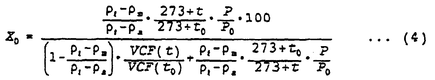
- X 0 = gas bubble content by volume percentage in the flowing liquid at t 0°C and P 0 kg/cm2 abs.
- ρℓ = density of gas-tree liquid in g/cm3 at t°C and P kg/cm2 abs.
- ρa = gas density in g/cm3 at t°C and P kg/cm2 abs.
- ρm = average density of the flowing liquid in g/cm3 at t°C and P kg/cm2 abs calculated in accordance with a volumetric flow rate (Vf) and a mass flow rate (Wf) of the flowing liquid (ρm = Wf/Vf).
- t 0 = normalized temperature in °C.
- t = flowing liquid temperature in °C
- P 0 = normalized pressure in kg/cm2 abs.
- P = flowing liquid pressure in kg/cm2 abs.
- VCF (t 0 ) = volume correction factor of gas-free liquid at a temperature of t 0°C, VCF (t 0 ) = ρℓ.0/ρℓ.15, where ρℓ.15 and ρℓ.0 are the density of gas-free liquid at a temperature of 15°C and t 0 °C, respectively.
- VCF(t) = volume correction factor of gas-free liquid at a temperature of t°C. VCF(t) = ρℓ /ρℓ.15, where ρℓ.15 and ρℓ are the density of gas-free liquid at a temperature of 15°C and t°C, respectively.
- In the above formula (4), the denominator


- Fig. 5 is a diagram indicating schematically the obtention of the various parameters and the calculations carried out by the data processor.
- in the device provided in accordance with the present invention, date necessary for the calculation of the bubble content of the flowing liquid are entered through the control panel. The bubble-containing liquid is then caused to flow through the conveyance passage or the bypass. If the liquid is caused to flow through the conveyance passage, the mass flow rate, volumetric flow rate, pressure and temperature of the liquid are measured and the calculations are thereafter made by the pressure signal amplifier, the temperature signal amplifier and the bubble content calculation circuit. If the liquid is caused to flow through the bypass, the liquid is introduced into the bypass by the pump having a circulating function for pulverizing the bubble in the liquid to uniformly disperse the pulverized elements of the bubble, the mass flow rate, volumetric flow rate, pressure and temperature of the liquid are then measured, and the calculations are thereafter made by the above-mentioned amplifier and circuit. The bubble content of the liquid flowing in the conveyance passage or the bypass passage can then be dynamically, quickly and accurately determined in terms of the standard pressure and the standard temperature, and then displayed to the operator on the bubble content display panel.
- When the bubble content of the flowing liquid at high pressure and that of the liquid at low pressure are to be alternately measured by the device through shifting the passage changeover valves, the liquid is caused to flow through the conveyance passage or the bypass and set at high pressure or low pressure by the pressure regulation valves, and the order of flow of the liquid through the mass flowsensor and that of the liquid through the volumetric flowsensor is then altered by shifting the passage changeover valves, so that the mass flow rate, volumetric flow rate, pressure and temperature of the liquid are measured at high pressure or at low pressure. The measured quantities are subjected to the calculations by the pressure signal amplifier, the temperature signal amplifier and the bubble content calculation circuit so that the bubble content of the liquid at high pressure and of low pressure is determined in terms of the standard pressure and the standard temperature, and displayed on the bubble content display panel. The bubble content of the flowing liquid at high pressure and at low pressure can thus be alternately measured, and then indicated on the panel.
- When the bubble content of the flowing liquid at high pressure set by the pressure regulation valves and that of the flowing liquid at low pressure set by the valves are to be simultaneously measured by the device, the bubble-containing liquid is caused to flow through the conveyance passage or the bypass, the volumetric flow rate, pressure and temperature of the liquid set at high pressure are measured, the mass flow rate of the liquid is then measured, and the volumetric flow rate, pressure and temperature of the liquid set at low pressure by the downstream pressure regulation valve are thereafter measured. The measured quantities are subjected to calculations by the pressure signal amplifier, the temperature signal amplifier and the bubble content calculation circuit for high pressure and for low pressure so that the bubble content of the liquid at high pressure and low pressure are determined in terms of the standard pressure and the standard temperature in accordance with calculation formulae (1) and (2), and then indicated on the respective bubble content display panels.
- In accordance with calculation formula (3), the difference between the bubble content of the liquid at low pressure and that of the liquid at high pressure can be determined as the bubble quantity of the dissolved gas in the liquid due to the change in the pressure thereof.
-
- Fig. 1 is a cutaway view of an integrated-type device of the invention for dynamically measuring the bubble content of a flowing liquid, which is directly installed in a conveyance passage for the liquid, according to one embodiment of the invention
- Fig. 2 is a block diagram of the device of Fig. 1;
- Fig. 3 is a cutaway view of a separate type device for dynamically measuring the bubble content of a flowing liquid, which is installed in a bypass for the liquid, according to another embodiment of the invention;
- Fig. 4 is a block diagram of the separate type device; and
- Fig 5. is a diagram showing the operation of a data processor used in the above embodiments.
- Two preferred embodiments of the present invention are hereafter described. However, the invention is not confined to these embodiments.
- One of the two preferred embodiments (see Fig. 1, 2) is an integrated-type device intended for dynamically measuring the bubble content of a flowing liquid and which is installed in the mixed oil conveyance passage of a mixer for mixing a lubricating oil with a polymer. The device includes a
pressure sensor 5, apressure signal amplifier 6, atemperature sensor 7, atemperature signal amplifier 8, avolumetric flowsensor 9, avolumetric flow amplifier 30, amass flowsensor 10, amass flow amplifier 31,pressure regulation valves 11,passage changeover valves 12, a bubblecontent calculation circuit 13 which operates in accordance with bubble content calculation formulae (1) and (2) above, acontrol panel 14, a bubblecontent display panel 15, apressure display panel 16 and atemperature display panel 17, as shown in Figs. 1 and 2. These components are provided inhousing box 18. Thepressure sensor 5, thetemperature sensor 7, thevolumetric flowsensor 9, themass flowsensor 10, thepressure regulation valves 11 and thepassage changeover valves 12 are connected to each other by pipes as shown. Thehousing 18 is provided in theconveyance passage 1 of the mixer in such a manner that the pipes of the device are connected to the passage by pipe joints A. Thesensors flowsensors flow amplifiers amplifiers circuit 13, and thepanels control panel 14 can be manipulated in front of the device. The values shown on the bubblecontent display panel 15, thepreseure display panel 16 and thetemperature display panel 17 can be seen in front of the device. - The second embodiment (see Fig. 3, 4) is a separate type device intended for dynamically measuring the bubble content of a flowing liquid and which is installed in a bypass of the lubricating oil conveyance passage of a 2,000 cc four-cycle engine for a motor vehicle. The device includes a
pump 3 having a function of circulating the liquid in the pump, a connection pipe 4, a high-pressure section including apressure sensor 5, apressure signal amplifier 6, atemperature sensor 7, atemperature signal amplifier 8, avolumetric flowsensor 9, avolumetric flow amplifier 30, apressure regulation valve 11, a bubblecontent calculation circuit 13 operating in accordance with calculation formula (1) above, a bubblecontent display panel 15, apressure display panel 16 and atemperature display panel 17, a low-pressure section including apressure sensor 5, apressure signal amplifier 6, atemperature sensor 7, atemperature signal amplifier 8, avolumetric flowsensor 9, avolumetric flow amplifier 30, apressure regulation valve 11, a bubblecontent calculation circuit 13 operating in accordance with calculation formula (2), a bubblecontent display panel 15, apressure display panel 16 and atemperature display panel 17, amass flowsensor 10, amass flow amplifier 31, and acontrol panel 14, as shown in Figs. 3 and 4. These components are provided inhousing boxes 18. Two tapped holes are provided in the lubricatingoil conveyance passage 1 of the engine. Thebypass 2 is connected to the passage by pipe joints A screw-engaged in the tapped holes. The sensors, the amplifiers the calculation circuits, the flowsensors, the flow amplifiers and the panels are electrically coupled together by wires so that the device is composed of a bubblecontent measuring detector 19 connected to thebypass 2, and a bubble content measuringdata processor 20 electrically coupled to the detector. - With the device of the present invention, a flowing liquid containing bubbles does not need to be extracted from a passage for the liquid for measuring the bubble content of the liquid. For this reason, the bubble content can be measured as he liquid remains flowing in the passage. Moreover, the bubbles do not disappear by the measurement. Since pressure regulation valves, a volumetric flowsensor, a mass flowsensor and so forth are provided and novel calculation formulae are employed, the bubble content can be dynamically, quickly and accurately measured not only at high pressure, as in the conventional case, but also at low pressure, and the bubble quantity of the dissolved gas in the liquid due to a change in the pressure thereof can be dynamically, quickly and accurately measured.
- The bubble content measuring detector of a separate type device such as the second embodiment can be used in a severe environment of high or low temperature, while the bubble content measuring data processor of the device can be used in a normal environment. For this reason, the range of use of the device is wide. Since a pump having a function of circulating the liquid is provided to pulverize the bubbles in the liquid at the time of introduction of the liquid into the device to uniformly disperse the pulverized elements of the bubbles, the dispersion in the measured value of the bubble content of the liquid is reduced. Although it is difficult to obtain accurate data as to tha bubble content of a flowing liquid in a conventional device, the bubble content can be continuously measured under various conditions in accordance with the present invention to make it easier to control the quality of each of various kinds of liquids.
- The present invention can be utilized for research as well as for practical use. Since the maximum rotational speeds of automobile and motorcycle engines have recently been increased, the bubble content of the lubricating oil for the engine has become very large. The bubbles are likely to do various kinds of harm to the hydraulic mechanism and sliding surfaces of the engine. However, since there has not been a method for quickly and accurately measuring the bubble content of the lubricating oil under varioJs conditions during the actual flow of the oil, it was difficult to fully clarify the quantitative relationship between the bubble content and the degree and type of the damage. The present invention can be applied for such full clarification in research.
Claims (5)
- A device for dynamically measuring a bubble content of a flowing liquid at both high and low pressure and a bubble quantity of dissolved gas due to a change in pressure of said liquid during the flowing thereof, comprising:a) means (5,6;7,8;9,30) for measuring a pressure, a temperature and a volumetric flow rate of said liquid in a conveyance passage or a bypass passage (2) for said conveyance passage (1) for said liquid at high and low pressure points thereof and means (10, 31) for measuring a mass flow rate of said liquid between said high and low pressure points; andb) means (13) for calculating the bubble content and the bubble quantity of the dissolved gas in said liquid in accordance with the measured values of said pressure, said temperature, said volumetric flow rate and said mass flow rate.
- The device of claim 1, further comprising a passage changeover valve means (12) for switching a flow of said liquid to determine said high and low pressure points.
- The device of claim 1, where said calculating means (13) calculates said bubble content in accordance with a following formula:
 X0 = gas bubble content by volume percentage in said liquid at t0°C and P0 kg/cm2 abs.pℓ = density of gas-free liquid in g/cm3 at t°C and P kg/cm2 abs.pa = gas density in g/cm3 at t°C and P kg/cm2 abs.pm = average density of said liquid in g/cm3 at t°C and P kg/cm2 abs. calculated in accordance with said volumetric flow rate (Vf) and said mass flow rate (Wf) of said liquid (pm = Wf/Vf)t0 = normalized temperature in °Ct = said liquid temperature in °CP0 = normalized pressure in kg/cm2 abs.P = said liquid pressure in kg/cm2 abs.VCF(t0) = volume correction factor of gas-free liquid at a temperature of t0°C. VCF(t0) = pℓ.0/pℓ.15, where pℓ.15 and pℓ.0 are the density of gas-free liquid at a temperature of 15°C and t°C, respectively.VCF(t) = volume correction factor of gas-free liquid at a temperature of t°C. VCF(t) = pℓ /pℓ.15, where pℓ.15 and pℓ are the density of gas-free liquid at a temperature of 15°C and t°C, respectively.
 - A device according to claim 1, wherein said means for measuring comprises a pressure regulation valve (11) for regulating a pressure of said liquid.
- A device according to claim 1, further comprising:- a pump (3) having a function of circulating the liquid in the pump, which is connected between an inlet bypass line and an upstream pressure regulating valve (11); and- a high pressure section and a low pressure section having said means for measuring, independently.
Applications Claiming Priority (2)
| Application Number | Priority Date | Filing Date | Title |
|---|---|---|---|
| JP2297151A JP2643020B2 (en) | 1990-11-05 | 1990-11-05 | Dynamic determination device for bubble content in flowing liquid |
| JP297151/90 | 1990-11-05 |
Publications (2)
| Publication Number | Publication Date |
|---|---|
| EP0484876A1 EP0484876A1 (en) | 1992-05-13 |
| EP0484876B1 true EP0484876B1 (en) | 1997-07-30 |
Family
ID=17842858
Family Applications (1)
| Application Number | Title | Priority Date | Filing Date |
|---|---|---|---|
| EP91118831A Expired - Lifetime EP0484876B1 (en) | 1990-11-05 | 1991-11-05 | Device for dynamically measuring bubble content of flowing liquid |
Country Status (4)
| Country | Link |
|---|---|
| US (1) | US5295083A (en) |
| EP (1) | EP0484876B1 (en) |
| JP (1) | JP2643020B2 (en) |
| DE (1) | DE69127051T2 (en) |
Cited By (2)
| Publication number | Priority date | Publication date | Assignee | Title |
|---|---|---|---|---|
| EP1632776A2 (en) | 2004-09-02 | 2006-03-08 | F. Hoffmann-La Roche AG | Method of detecting a gas bubble in an aqueous liquid |
| EP1632773A1 (en) | 2004-09-02 | 2006-03-08 | F. Hoffmann-Roche AG | Method of detecting an air bubble in an aqueous liquid |
Families Citing this family (21)
| Publication number | Priority date | Publication date | Assignee | Title |
|---|---|---|---|---|
| US5510019A (en) | 1993-07-30 | 1996-04-23 | Mitsubishi Oil Co., Ltd. | Bubble separating apparatus |
| US5965805A (en) * | 1997-09-30 | 1999-10-12 | Exxon Chemical Patents Inc. | Apparatus and method for determining the air entrainment characteristics of liquids |
| US6249748B1 (en) * | 1998-12-08 | 2001-06-19 | National Science Council | Apparatus and method for determining a flow rate of a fluid substance discharged from a reserving device |
| EP1232382B1 (en) * | 1999-10-29 | 2009-01-21 | Radiometer Medical Aps | Method and apparatus for detection of a bubble in a liquid |
| US20040209373A1 (en) * | 2001-11-26 | 2004-10-21 | Dexsil Corporation | Method and apparatus for the determination of water in materials |
| US6766680B2 (en) * | 2002-01-16 | 2004-07-27 | Appleton Papers, Inc. | Determination of gas solubility, entrained gas content, and true liquid density in manufacturing processes |
| US7086278B2 (en) | 2003-01-21 | 2006-08-08 | Cidra Corporation | Measurement of entrained and dissolved gases in process flow lines |
| US20060048583A1 (en) | 2004-08-16 | 2006-03-09 | Gysling Daniel L | Total gas meter using speed of sound and velocity measurements |
| AT412515B (en) | 2003-08-07 | 2005-03-25 | Hoffmann La Roche | METHOD FOR DETECTING A GAS BUBBLE IN A LIQUID |
| US7117717B2 (en) * | 2003-12-12 | 2006-10-10 | Invensys Systems, Inc. | Densitometer with pulsing pressure |
| KR100552210B1 (en) * | 2004-06-28 | 2006-02-13 | 현대자동차주식회사 | Air mixing rate measuring device and measuring method of test engine for setting minimum oil level in engine design |
| WO2008109841A1 (en) | 2007-03-07 | 2008-09-12 | Invensys Systems, Inc. | Coriolis frequency tracking |
| US8033157B2 (en) | 2007-10-01 | 2011-10-11 | Baxter International Inc. | Medical fluid air bubble detection apparatus and method |
| DE102009034318A1 (en) * | 2009-07-23 | 2011-01-27 | Block, Ralf, Dipl.-Ing. | Method and device for determining the operating gas volume |
| GB2497321B (en) * | 2011-12-06 | 2014-06-18 | Senico Ltd | Multi-phase metering of fluid flows |
| US9920878B2 (en) * | 2012-04-20 | 2018-03-20 | Lincoln Industrial Corporation | Lubrication system and controller |
| US9863798B2 (en) * | 2015-02-27 | 2018-01-09 | Schneider Electric Systems Usa, Inc. | Systems and methods for multiphase flow metering accounting for dissolved gas |
| JP6225281B2 (en) * | 2016-01-27 | 2017-11-01 | Jfeエンジニアリング株式会社 | Bubble detection device and condensing equipment using the bubble detection device |
| WO2018131194A1 (en) * | 2017-01-12 | 2018-07-19 | Jfeエンジニアリング株式会社 | Bubble detection device, and condensing equipment using said bubble detection device |
| CN110146647A (en) * | 2019-03-23 | 2019-08-20 | 韩旭 | Detection device and method for gas content in high viscosity liquid |
| WO2021163168A1 (en) * | 2020-02-11 | 2021-08-19 | Quaker Chemical Corporation | Measurement and control of entrained air and foam in metalworking fluids |
Citations (1)
| Publication number | Priority date | Publication date | Assignee | Title |
|---|---|---|---|---|
| US5041990A (en) * | 1989-01-10 | 1991-08-20 | Mitsubishi Oil Co., Ltd. | Method and apparatus for measuring entrained gas bubble content of flowing fluid |
Family Cites Families (4)
| Publication number | Priority date | Publication date | Assignee | Title |
|---|---|---|---|---|
| JPS58223039A (en) * | 1982-06-22 | 1983-12-24 | Mitsubishi Heavy Ind Ltd | Method for measuring density of slurry |
| US4763525A (en) * | 1986-04-16 | 1988-08-16 | The Standard Oil Company | Apparatus and method for determining the quantity of gas bubbles in a liquid |
| JPS6382342A (en) * | 1986-09-26 | 1988-04-13 | Polyurethan Eng:Kk | Measurement for amount of gas in liquid mixed therewith |
| US4941361A (en) * | 1988-06-20 | 1990-07-17 | Lew Hyok S | Three-in-one flowmeter |
-
1990
- 1990-11-05 JP JP2297151A patent/JP2643020B2/en not_active Expired - Lifetime
-
1991
- 1991-11-04 US US07/787,606 patent/US5295083A/en not_active Expired - Fee Related
- 1991-11-05 DE DE69127051T patent/DE69127051T2/en not_active Expired - Fee Related
- 1991-11-05 EP EP91118831A patent/EP0484876B1/en not_active Expired - Lifetime
Patent Citations (1)
| Publication number | Priority date | Publication date | Assignee | Title |
|---|---|---|---|---|
| US5041990A (en) * | 1989-01-10 | 1991-08-20 | Mitsubishi Oil Co., Ltd. | Method and apparatus for measuring entrained gas bubble content of flowing fluid |
Cited By (5)
| Publication number | Priority date | Publication date | Assignee | Title |
|---|---|---|---|---|
| EP1632776A2 (en) | 2004-09-02 | 2006-03-08 | F. Hoffmann-La Roche AG | Method of detecting a gas bubble in an aqueous liquid |
| EP1632773A1 (en) | 2004-09-02 | 2006-03-08 | F. Hoffmann-Roche AG | Method of detecting an air bubble in an aqueous liquid |
| US7807041B2 (en) | 2004-09-02 | 2010-10-05 | Roche Diagnostics Operations, Inc. | Method for detecting the presence or absence of a gas bubble in an aqueous liquid |
| US7867375B2 (en) | 2004-09-02 | 2011-01-11 | Roche Diagnostics Operations, Inc. | Method for detecting the presence or absence of a gas bubble by dynamic sensor response |
| US8354015B2 (en) | 2004-09-02 | 2013-01-15 | Roche Diagnostics Operations, Inc. | Detection of the presence or absence of a gas bubble by dynamic sensor response |
Also Published As
| Publication number | Publication date |
|---|---|
| JPH04172230A (en) | 1992-06-19 |
| DE69127051T2 (en) | 1998-01-02 |
| JP2643020B2 (en) | 1997-08-20 |
| EP0484876A1 (en) | 1992-05-13 |
| US5295083A (en) | 1994-03-15 |
| DE69127051D1 (en) | 1997-09-04 |
Similar Documents
| Publication | Publication Date | Title |
|---|---|---|
| EP0484876B1 (en) | Device for dynamically measuring bubble content of flowing liquid | |
| US4773257A (en) | Method and apparatus for testing the outflow from hydrocarbon wells on site | |
| US5211842A (en) | Three-phase well test apparatus using pumped recirculation to maintain homogenous flow | |
| US6612187B1 (en) | Measuring a gas mass fraction | |
| US4689989A (en) | Method and apparatus for testing the outflow from hydrocarbon wells on site | |
| CA2103254C (en) | Apparatus and method for measuring two or three phase fluid flow utilizing one or more momentum flow meters and a volumetric flow meter | |
| US7640813B2 (en) | Process for operating a Coriolis mass flow rate measurement device | |
| EP0690292A2 (en) | Multi-phase fluid flow monitor and method | |
| US11982556B2 (en) | Wet gas flow rate metering method based on a coriolis mass flowmeter and device thereof | |
| CA2001030C (en) | Method and apparatus for measuring entrained gas bubble content of flowing fluid | |
| EP0316688B1 (en) | Gas sampling device | |
| CA2054985C (en) | Device for dynamically measuring bubble content of flowing liquid | |
| US4649734A (en) | Apparatus and method for calibrating a flow meter | |
| JP2913491B2 (en) | Flow measurement device | |
| US4289018A (en) | Method and apparatus for measuring degasification | |
| Johnson et al. | Development of a turbine meter for two-phase flow measurement in vertical pipes | |
| US3453868A (en) | Specific gravity measuring system for interface detection | |
| JPH02124445A (en) | Dynamic determining method and determining apparatus for content of gas in flowing liquid | |
| JP2000249579A (en) | Flow measurement method and differential pressure type flow meter using the same | |
| GB2336681A (en) | Measuring a gas mass fraction | |
| RU59715U1 (en) | OIL, GAS AND WATER WELL PRODUCT METER | |
| US11815524B2 (en) | Volume fraction meter for multiphase fluid flow | |
| SU802869A1 (en) | Method of measuring the volume of gas non-dissolved in working liquids of hydraulic systems | |
| JPH06213700A (en) | Flow meter difference test device | |
| JPH03145597A (en) | Method for determining discharge flow rate of rotary pump |
Legal Events
| Date | Code | Title | Description |
|---|---|---|---|
| PUAI | Public reference made under article 153(3) epc to a published international application that has entered the european phase |
Free format text: ORIGINAL CODE: 0009012 |
|
| AK | Designated contracting states |
Kind code of ref document: A1 Designated state(s): DE FR GB |
|
| 17P | Request for examination filed |
Effective date: 19920721 |
|
| 17Q | First examination report despatched |
Effective date: 19951222 |
|
| GRAG | Despatch of communication of intention to grant |
Free format text: ORIGINAL CODE: EPIDOS AGRA |
|
| GRAH | Despatch of communication of intention to grant a patent |
Free format text: ORIGINAL CODE: EPIDOS IGRA |
|
| GRAH | Despatch of communication of intention to grant a patent |
Free format text: ORIGINAL CODE: EPIDOS IGRA |
|
| GRAA | (expected) grant |
Free format text: ORIGINAL CODE: 0009210 |
|
| AK | Designated contracting states |
Kind code of ref document: B1 Designated state(s): DE FR GB |
|
| REF | Corresponds to: |
Ref document number: 69127051 Country of ref document: DE Date of ref document: 19970904 |
|
| ET | Fr: translation filed | ||
| PLBE | No opposition filed within time limit |
Free format text: ORIGINAL CODE: 0009261 |
|
| STAA | Information on the status of an ep patent application or granted ep patent |
Free format text: STATUS: NO OPPOSITION FILED WITHIN TIME LIMIT |
|
| 26N | No opposition filed | ||
| REG | Reference to a national code |
Ref country code: FR Ref legal event code: TP |
|
| PGFP | Annual fee paid to national office [announced via postgrant information from national office to epo] |
Ref country code: GB Payment date: 19991103 Year of fee payment: 9 |
|
| PGFP | Annual fee paid to national office [announced via postgrant information from national office to epo] |
Ref country code: FR Payment date: 19991130 Year of fee payment: 9 |
|
| PGFP | Annual fee paid to national office [announced via postgrant information from national office to epo] |
Ref country code: DE Payment date: 19991216 Year of fee payment: 9 |
|
| REG | Reference to a national code |
Ref country code: GB Ref legal event code: 732E |
|
| PG25 | Lapsed in a contracting state [announced via postgrant information from national office to epo] |
Ref country code: GB Free format text: LAPSE BECAUSE OF NON-PAYMENT OF DUE FEES Effective date: 20001105 |
|
| GBPC | Gb: european patent ceased through non-payment of renewal fee |
Effective date: 20001105 |
|
| PG25 | Lapsed in a contracting state [announced via postgrant information from national office to epo] |
Ref country code: FR Free format text: LAPSE BECAUSE OF NON-PAYMENT OF DUE FEES Effective date: 20010731 |
|
| PG25 | Lapsed in a contracting state [announced via postgrant information from national office to epo] |
Ref country code: DE Free format text: LAPSE BECAUSE OF NON-PAYMENT OF DUE FEES Effective date: 20010801 |
|
| REG | Reference to a national code |
Ref country code: FR Ref legal event code: ST |