EP0484791A2 - Procédé et dispositif pour modulation externe d'une porteuse optique - Google Patents
Procédé et dispositif pour modulation externe d'une porteuse optique Download PDFInfo
- Publication number
- EP0484791A2 EP0484791A2 EP91118379A EP91118379A EP0484791A2 EP 0484791 A2 EP0484791 A2 EP 0484791A2 EP 91118379 A EP91118379 A EP 91118379A EP 91118379 A EP91118379 A EP 91118379A EP 0484791 A2 EP0484791 A2 EP 0484791A2
- Authority
- EP
- European Patent Office
- Prior art keywords
- polarity
- modulator
- optical
- accordance
- signal
- Prior art date
- Legal status (The legal status is an assumption and is not a legal conclusion. Google has not performed a legal analysis and makes no representation as to the accuracy of the status listed.)
- Granted
Links
Images

Classifications
-
- G—PHYSICS
- G02—OPTICS
- G02F—OPTICAL DEVICES OR ARRANGEMENTS FOR THE CONTROL OF LIGHT BY MODIFICATION OF THE OPTICAL PROPERTIES OF THE MEDIA OF THE ELEMENTS INVOLVED THEREIN; NON-LINEAR OPTICS; FREQUENCY-CHANGING OF LIGHT; OPTICAL LOGIC ELEMENTS; OPTICAL ANALOGUE/DIGITAL CONVERTERS
- G02F1/00—Devices or arrangements for the control of the intensity, colour, phase, polarisation or direction of light arriving from an independent light source, e.g. switching, gating or modulating; Non-linear optics
- G02F1/29—Devices or arrangements for the control of the intensity, colour, phase, polarisation or direction of light arriving from an independent light source, e.g. switching, gating or modulating; Non-linear optics for the control of the position or the direction of light beams, i.e. deflection
- G02F1/31—Digital deflection, i.e. optical switching
- G02F1/313—Digital deflection, i.e. optical switching in an optical waveguide structure
- G02F1/3136—Digital deflection, i.e. optical switching in an optical waveguide structure of interferometric switch type
-
- H—ELECTRICITY
- H04—ELECTRIC COMMUNICATION TECHNIQUE
- H04B—TRANSMISSION
- H04B10/00—Transmission systems employing electromagnetic waves other than radio-waves, e.g. infrared, visible or ultraviolet light, or employing corpuscular radiation, e.g. quantum communication
- H04B10/50—Transmitters
- H04B10/501—Structural aspects
- H04B10/503—Laser transmitters
- H04B10/505—Laser transmitters using external modulation
-
- G—PHYSICS
- G02—OPTICS
- G02F—OPTICAL DEVICES OR ARRANGEMENTS FOR THE CONTROL OF LIGHT BY MODIFICATION OF THE OPTICAL PROPERTIES OF THE MEDIA OF THE ELEMENTS INVOLVED THEREIN; NON-LINEAR OPTICS; FREQUENCY-CHANGING OF LIGHT; OPTICAL LOGIC ELEMENTS; OPTICAL ANALOGUE/DIGITAL CONVERTERS
- G02F2203/00—Function characteristic
- G02F2203/19—Function characteristic linearised modulation; reduction of harmonic distortions
Definitions
- the present invention relates to optical modulators, and more specifically to a technique for linearizing the output of an external optical intensity modulator.
- analog communication systems provide an efficient use of bandwidth. This is particularly useful in cable television (CATV) transmission system applications, where it is necessary to transmit a large number of video channels through an optical fiber. Compatibility with existing equipment is achieved by using the same signal format for optical transmission that is in use for coaxial cable signal transmission.
- CATV cable television
- a light beam (carrier) must be modulated with the information signal.
- the "electrooptic effect” has been advantageously used to provide modulators for this purpose.
- electrooptic modulators using miniature guiding structures are known which operate with a low modulating power.
- an electrooptic modulator In electrooptic modulators, the electric field induced linear birefringence in an electrooptic material produces a change in the refractive index of the material which, in turn, impresses a phase modulation upon a light beam propagating through the material.
- the phase modulation is converted into intensity modulation by the addition of polarizers or optical circuitry.
- an electrooptic modulator should have a linear relationship between its output optical power and the applied modulating voltage.
- an optical carrier (laser beam) is split into two paths. At least one path is electrically phase modulated. The two signals are then recombined in an interferometer to provide an intensity modulated carrier.
- lithium niobate (LiNbO3) is used as the electrooptic material. Waveguides in such materials are readily formed by titanium indiffusion.
- the output power curve of a Mach Zehnder modulator is nonlinear.
- Practical analog optical communications systems demand a high linearity. See, for example, W.I. Way, "Subcarrier Multiplexed Lightwave System Design Considerations for Subscriber Loop Applications", J. Lightwave Technol., Vol. 7, pp. 1806-1818 (1989).
- Modulator nonlinearities cause unacceptable harmonic and intermodulation distortions.
- intermodulation distortions can impose serious limitations on the system performance.
- the second order IMD can be filtered out if the bandwidth is less than one octave.
- CATV transmission systems operate with bandwidths of many octaves.
- the third order IMD can only be eliminated by using devices with linear characteristics.
- Injection lasers for example, are not perfectly linear. They can be limited by second order or third order IMD. By using biases well above the threshold and small optical modulation depths, selected injection lasers can barely meet vestigial sideband amplitude modulation CATV system specifications. This limitation is discussed in G.E. Bodeep and T.E. Darcie, "Semiconductor Lasers Versus External Modulators: A Comparison of Nonlinear Distortion for Lightwave Subcarrier CATV Applications", I.E.E.E. Photonics Technol. Lett., Vol. 1, pp. 401-403 (1989).
- optical circuit level compensation technique for linearizing the output of an external optical intensity modulator. It would be further advantageous to provide such a modulator in which IMD distortions are reduced to an acceptably low level.
- Such apparatus would have particular application in optical fiber CATV distribution systems, wherein a plurality of television channel signals are multiplexed and carried over a single fiber. It would also be advantageous to provide such apparatus that is economical, readily manufacturable, and reliable. The present invention provides such apparatus.
- an optical modulator comprises means for splitting an optical signal for communication over first and second paths. At least the first path comprises an electrooptic material. An electric field of a first polarity is applied across the first path to phase modulate the signal therein. An electrooptic directional coupler is coupled to the first and second paths. An electric field of a second polarity opposite to the first polarity is applied across the directional coupler to couple optical signals from the first and second paths into an output signal.
- Means are provided for biasing the first path at an inflection point to provide a substantially 45° phase shift when no modulating signal is present.
- the biasing means can comprise a set of electrodes for applying an electric field across the first path.
- the bias field is of the same "first" polarity used for the phase modulation.
- the means for applying the first polarity electric field can comprise a first set of modulating signal electrodes.
- the means for applying the second polarity electric field can comprise a second set of modulating signal electrodes.
- the optical signal is equally split into the first and second paths with a Y-branch optical power splitter.
- the second path of the optical modulator can also comprise an electrooptic material. An electric field applied across the second path will then phase modulate the signal therein. Phase modulation of the signal in both the first and second paths can provide a device with greater sensitivity.
- the phase modulation provided by the first and second polarity electric fields originates with a common modulating signal.
- the magnitude of the common modulating signal is scaled to modulate the second polarity field at a slightly different level than the first polarity field. This technique is used to minimize distortions in the output signal.
- the directional coupler of the preferred embodiment has a nominal effective coupling length of ⁇ /4.
- the present invention provides a linearized optical intensity modulator that can be fabricated from a Y-branch optical power splitter having a first pair of electrodes and a directional coupler having a second pair of electrodes.
- the electrode pairs are biased at opposite polarities with respect to each other.
- the signal driving each pair will have a different slope at the quadrature point corresponding to the bias polarity of the pair.
- Correction of harmonic nonlinearities results from the provision of a desired coupling coefficient at the directional coupler. Since all compensation is provided in a single substrate, a low cost device is obtained.
- Figure 1 illustrates a first embodiment of a linear electrooptic modulator in accordance with the present invention.
- An optical carrier e.g., laser beam
- a pair of modulation signal electrodes 26, 28 provides an electric field across first path 14 when a modulating signal V S is input at terminal 24.
- the field across first path 14 will have a first polarity as indicated in Figure 1.
- a separate pair of bias electrodes 32, 34 is provided to establish a bias field across first path 14 upon the application of a bias voltage V B at terminal 30.
- the bias voltage biases first path 14 at the inflection point of ⁇ /4 (i.e., to provide a 45° phase shift to the optical signal propagating therethrough).
- a directional coupler generally designated 18 couples light from the first and second paths 14, 16 respectively for output at terminals 20, 22.
- the directional coupler is fabricated from an electrooptic material that responds to an electric field provided thereacross.
- the electric field is provided by a pair of electrodes 36, 40.
- the modulating signal V S scaled by a factor ⁇ is input at terminal 42 to provide an electric field across the directional coupler at a polarity opposite to the electric field across first path 14.
- Figure 2 illustrates an alternate embodiment of the present invention wherein an electric field is provided across second path 16 of the Mach Zehnder modulator by additional electrodes 29, 35.
- Input of the signal voltage V S at terminal 31 establishes a field between electrode 28a and electrode 29 having the polarity indicated.
- Second path 16 is biased by an electric field between electrodes 34a and 35 when the bias voltage V B is input to terminal 37.
- the provision of electrodes adjacent both the first and second paths provides a modulator having greater sensitivity.
- the modulator of the present invention is essentially a Mach Zehnder modulator followed by a directional coupler.
- Each device is separately known in the art. See, e.g., the article to Koai and Liu referred to above.
- these devices are combined into a novel structure wherein a common modulating signal is applied to both devices via separate electrodes and at opposite polarities.
- the use of separate DC bias electrodes 32, 34 on the Mach Zehnder portion avoids heating in the main electrode 26.
- the separate biasing electrodes do not require a termination resistor, and therefore only a minimal amount of power is consumed as compared to the alternative of applying the bias voltage together with the signal voltage to electrode 26.
- Y-branch optical power splitter 12 divides the optical power at terminal 10 equally into two arms of the Mach Zehnder modulator, which operates as a phase shifter.
- the directional coupler that follows the Mach Zehnder modulator has a nominal coupling constant length product kL, of ⁇ /4, i.e., half a coupling length.
- the output can be taken from either of the two output waveguides at terminals 20, 22.
- the modulation signal applied to the phase shifter produces a ⁇ .
- the same modulation signal with a reversed polarity and a multiplication factor, ⁇ is applied to the directional coupler. This multiplication factor can be optimized for minimal distortions according to the value of kL.
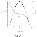
- I o represents the input power
- x is the AC modulation signal
- ⁇ is essentially the DC bias.
- the coefficient of the linear term determines the efficiency of the modulator.
- the coefficients of the second order and the third order terms for the modulator of Figure 1 are shown in Figure 3 as a function of ⁇ .
- ⁇ is assumed to be 0.947.
- the coefficient of the third order term may be zero at one or two values of ⁇ .
- the present modulator In comparison with a Mach Zehnder interferometer, the present modulator, using optimal kL and ⁇ , requires over twice the modulation voltage magnitude to obtain a similar modulation depth. However, the third order harmonic and intermodulation distortions are orders of magnitude lower than those of a conventional Mach Zehnder interferometer.
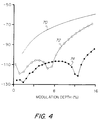
- Figure 4 illustrates the third harmonic distortions, defined as 20 log (harmonic content/linear term), versus the optical modulation depth for a conventional Mach Zehnder interferometer (solid curve 70) and for two different linear modulators in accordance with the present invention.
- IMD is present in addition to harmonic distortions.
- the third order IMD is three times (i.e, 9.54 dB higher than) the third order harmonic distortion plotted in Figure 4.
- the Mach Zehnder interferometer alone can only offer an optical modulation depth of 1.3%.
- any deviation can be partially compensated for by adjusting ⁇ .
- the modulation efficiency may be further reduced.
- Distortions are also larger as shown in Figure 4.
- the dips in Figure 4 result from details in the dependence of the third order coefficient ⁇ 3 on ⁇ . The positions of these dips can be varied.
- the distortion performance can be improved at large modulation depths if a slight deterioration in the distortion performance at small modulation depths can be tolerated.
- the second order distortions of such electrooptic modulators are always below -120 dB when they are biased at their inflection points.
- ⁇ (which establishes the scaling of the modulating signal applied to the directional coupler electrodes) must be tightly controlled. A deviation of just 2.5% from the optimal value can increase the third order distortions by 20 dB.
- the present invention provides a linear electrooptic external amplitude modulator. Both the second order and third order terms can be nulled simultaneously at zero DC bias. Second order distortions are well below those required for CATV transmission systems. With an optical modulation depth of up to 16% for each channel, third order IMD on the order of -95 dB is achievable.
- the use of an electrooptic modulator as described in conjunction with diode-pumped solid state lasers provides superior performance than directly modulated injection lasers for CATV applications.
Applications Claiming Priority (2)
| Application Number | Priority Date | Filing Date | Title |
|---|---|---|---|
| US609808 | 1990-11-06 | ||
| US07/609,808 US5119447A (en) | 1990-11-06 | 1990-11-06 | Apparatus and method for externally modulating an optical carrier |
Publications (3)
| Publication Number | Publication Date |
|---|---|
| EP0484791A2 true EP0484791A2 (fr) | 1992-05-13 |
| EP0484791A3 EP0484791A3 (en) | 1992-12-30 |
| EP0484791B1 EP0484791B1 (fr) | 1995-07-12 |
Family
ID=24442423
Family Applications (1)
| Application Number | Title | Priority Date | Filing Date |
|---|---|---|---|
| EP91118379A Expired - Lifetime EP0484791B1 (fr) | 1990-11-06 | 1991-10-29 | Procédé et dispositif pour modulation externe d'une porteuse optique |
Country Status (8)
| Country | Link |
|---|---|
| US (1) | US5119447A (fr) |
| EP (1) | EP0484791B1 (fr) |
| JP (1) | JP2698797B2 (fr) |
| CA (1) | CA2054337C (fr) |
| DE (1) | DE69111184T2 (fr) |
| HK (1) | HK90397A (fr) |
| MX (1) | MX9101952A (fr) |
| NO (1) | NO306082B1 (fr) |
Cited By (8)
| Publication number | Priority date | Publication date | Assignee | Title |
|---|---|---|---|---|
| WO1997019528A1 (fr) * | 1995-11-20 | 1997-05-29 | British Telecommunications Public Limited Company | Emetteur optique |
| FR2762944A1 (fr) * | 1997-04-30 | 1998-11-06 | France Telecom | Convertisseur electrique-optique capable de produire un spectre optique a bande laterale unique |
| US6426821B1 (en) | 1998-11-04 | 2002-07-30 | Corvis Corporation | Optical upconverter apparatuses, methods and systems |
| WO2002091074A1 (fr) * | 2001-05-03 | 2002-11-14 | Hrl Laboratories, Llc | Procede et appareil permettant de moduler un signal optique |
| US6525682B2 (en) | 2001-05-03 | 2003-02-25 | Hrl Laboratories, Llc | Photonic parallel analog-to-digital converter |
| US6529305B1 (en) | 1998-11-04 | 2003-03-04 | Corvis Corporation | Optical transmission apparatuses, methods, and systems |
| US6925212B2 (en) | 1998-11-04 | 2005-08-02 | Corvis Corporation | Optical transmission apparatuses, methods, and systems |
| US7499603B1 (en) | 2006-01-19 | 2009-03-03 | Lockheed Martin Corporation | Range extended electrooptic modulator |
Families Citing this family (37)
| Publication number | Priority date | Publication date | Assignee | Title |
|---|---|---|---|---|
| FR2670589B1 (fr) * | 1990-12-14 | 1994-04-15 | Thomson Csf | Dispositif de modulation electrooptique integre. |
| SE468267B (sv) * | 1991-04-10 | 1992-11-30 | Ericsson Telefon Ab L M | Terminal foer ett frekvensdelat, optiskt kommunikationssystem |
| JPH0534650A (ja) * | 1991-05-10 | 1993-02-12 | Fujitsu Ltd | モニタ付分岐干渉型光変調器 |
| FR2685835A1 (fr) * | 1991-12-31 | 1993-07-02 | France Telecom | Systeme de transmission tres longue distance sur fibre optique a compensation des distorsions a la reception. |
| FR2685834B1 (fr) * | 1991-12-31 | 1995-03-31 | France Telecom | Systeme de transmission numerique longue distance sur fibre optique a compensation a l'emission des distorsions. |
| US5323406A (en) * | 1992-11-02 | 1994-06-21 | Yee Ting K | Photonic mixer for photonically multiplying two electrical signals in two optically interconnected interferometric modulators operated at modulation outside the linear range |
| US5347601A (en) * | 1993-03-29 | 1994-09-13 | United Technologies Corporation | Integrated optical receiver/transmitter |
| US5600473A (en) * | 1993-06-04 | 1997-02-04 | Ciena Corporation | Optical amplifier systems with add/drop multiplexing |
| US5579143A (en) * | 1993-06-04 | 1996-11-26 | Ciena Corporation | Optical system with tunable in-fiber gratings |
| DE4427523C1 (de) * | 1994-08-03 | 1996-01-11 | Iot Integrierte Optik Gmbh | Asymmetrisches integriert-optisches Mach-Zehnder-Interferometer |
| US5502782A (en) * | 1995-01-09 | 1996-03-26 | Optelecom, Inc. | Focused acoustic wave fiber optic reflection modulator |
| US5875048A (en) * | 1995-03-06 | 1999-02-23 | Cfx Communication Systems,Llc | Linear multi-output optical transmitter system |
| US5710653A (en) * | 1995-03-06 | 1998-01-20 | Fiber Optic Network Solutions Corp. | Linear multi-output optical transmitter system |
| US5515463A (en) * | 1995-03-10 | 1996-05-07 | Hewlett-Packard Company | Multi-branch microwave line for electro-optical devices |
| US5953139A (en) * | 1996-03-06 | 1999-09-14 | Cfx Communications Systems, Llc | Wavelength division multiplexing system |
| US6204951B1 (en) | 1997-05-21 | 2001-03-20 | Keotrel Solutions, Inc. | Electro-optic modulator with improved harmonic performance |
| US5915052A (en) * | 1997-06-30 | 1999-06-22 | Uniphase Telecommunications Products, Inc. | Loop status monitor for determining the amplitude of the signal components of a multi-wavelength optical beam |
| US6151157A (en) * | 1997-06-30 | 2000-11-21 | Uniphase Telecommunications Products, Inc. | Dynamic optical amplifier |
| US5982964A (en) * | 1997-06-30 | 1999-11-09 | Uniphase Corporation | Process for fabrication and independent tuning of multiple integrated optical directional couplers on a single substrate |
| US6370290B1 (en) | 1997-09-19 | 2002-04-09 | Uniphase Corporation | Integrated wavelength-select transmitter |
| US6031849A (en) * | 1997-11-14 | 2000-02-29 | Jds Uniphase Corporation | High power three level fiber laser and method of making same |
| US6020986A (en) * | 1997-11-21 | 2000-02-01 | Jds Uniphase Corporation | Programmable add-drop module for use in an optical circuit |
| US6282332B1 (en) | 1998-06-04 | 2001-08-28 | Pirelli Cavi E Sistemi S.P.A. | Waveguide structures in particular for use in acousto-optical mode converters and method for making same |
| JP2000137125A (ja) | 1998-06-04 | 2000-05-16 | Pirelli Cavi & Syst Spa | 拡散型光導波路構造を基板に製作する方法 |
| JP3600495B2 (ja) * | 1999-08-06 | 2004-12-15 | ソニー株式会社 | プラズマアドレス表示装置 |
| US6310990B1 (en) | 2000-03-16 | 2001-10-30 | Cidra Corporation | Tunable optical structure featuring feedback control |
| US7079780B1 (en) | 1999-05-28 | 2006-07-18 | Northrop Grumman Corporation | Linearized optical link using a single Mach-Zehnder modulator and two optical carriers |
| JP3703013B2 (ja) * | 2001-01-26 | 2005-10-05 | 日本電信電話株式会社 | 干渉計光回路及びその製造方法 |
| US7142788B2 (en) | 2002-04-16 | 2006-11-28 | Corvis Corporation | Optical communications systems, devices, and methods |
| GB2407644B (en) * | 2003-10-28 | 2007-06-20 | Filtronic Plc | A coplanar waveguide line |
| US7342467B2 (en) * | 2004-06-30 | 2008-03-11 | Harris Stratex Networks, Inc. | Variable power coupling device |
| GB2426073A (en) * | 2005-05-11 | 2006-11-15 | Filtronic Plc | Optical modulator |
| JP2007248850A (ja) * | 2006-03-16 | 2007-09-27 | Oki Electric Ind Co Ltd | マッハツェンダ型半導体素子及びその制御方法 |
| JP2012118272A (ja) * | 2010-11-30 | 2012-06-21 | Sumitomo Electric Ind Ltd | 光変調装置、光変調器の制御方法、及び光変調器の制御装置 |
| JP2013122546A (ja) * | 2011-12-12 | 2013-06-20 | Sumitomo Electric Ind Ltd | 半導体光位相変調器及びその駆動方法 |
| SG11201807888XA (en) * | 2016-03-18 | 2018-10-30 | Nippon Telegraph & Telephone | Optical modulator |
| CN112769492A (zh) | 2019-10-21 | 2021-05-07 | 富士通株式会社 | 监控直流偏置抖动信号的调制深度的方法、装置和光发射机 |
Citations (2)
| Publication number | Priority date | Publication date | Assignee | Title |
|---|---|---|---|---|
| WO1985001123A1 (fr) * | 1983-08-26 | 1985-03-14 | Hughes Aircraft Company | Commutateur de guides d'ondes optiques a haute frequence de commutation, modulateur et dispositifs de filtre |
| US4940305A (en) * | 1989-03-22 | 1990-07-10 | The Boeing Company | Optical switch based on 1×2 directional coupler |
Family Cites Families (6)
| Publication number | Priority date | Publication date | Assignee | Title |
|---|---|---|---|---|
| US4776657A (en) * | 1986-03-25 | 1988-10-11 | Tektronix, Inc. | Electro-optic phase shifter with reduced input capacitance |
| US4763974A (en) * | 1987-08-13 | 1988-08-16 | Trw Inc. | Δβ-Phase reversal coupled waveguide interferometer |
| US4936644A (en) * | 1989-06-13 | 1990-06-26 | Hoechst Celanese Corp. | Polarization-insensitive interferometric waveguide electrooptic modulator |
| US4932738A (en) * | 1989-06-13 | 1990-06-12 | Hoechst Celanese Corp. | Polarization-insensitive interferometric waveguide electrooptic modulator |
| US4936645A (en) * | 1989-08-24 | 1990-06-26 | Hoechst Celanese Corp. | Waveguide electrooptic light modulator with low optical loss |
| US5031235A (en) * | 1989-10-27 | 1991-07-09 | Hoechst Celanese Corp. | Cable system incorporating highly linear optical modulator |
-
1990
- 1990-11-06 US US07/609,808 patent/US5119447A/en not_active Expired - Lifetime
-
1991
- 1991-10-28 CA CA002054337A patent/CA2054337C/fr not_active Expired - Fee Related
- 1991-10-29 DE DE69111184T patent/DE69111184T2/de not_active Expired - Fee Related
- 1991-10-29 EP EP91118379A patent/EP0484791B1/fr not_active Expired - Lifetime
- 1991-11-04 NO NO914317A patent/NO306082B1/no not_active IP Right Cessation
- 1991-11-06 JP JP3317343A patent/JP2698797B2/ja not_active Expired - Fee Related
- 1991-11-06 MX MX9101952A patent/MX9101952A/es not_active IP Right Cessation
-
1997
- 1997-06-26 HK HK90397A patent/HK90397A/xx not_active IP Right Cessation
Patent Citations (2)
| Publication number | Priority date | Publication date | Assignee | Title |
|---|---|---|---|---|
| WO1985001123A1 (fr) * | 1983-08-26 | 1985-03-14 | Hughes Aircraft Company | Commutateur de guides d'ondes optiques a haute frequence de commutation, modulateur et dispositifs de filtre |
| US4940305A (en) * | 1989-03-22 | 1990-07-10 | The Boeing Company | Optical switch based on 1×2 directional coupler |
Non-Patent Citations (1)
| Title |
|---|
| JOURNAL OF LIGHTWAVE TECHNOLOGY. vol. 7, no. 10, October 1989, NEW YORK US pages 1601 - 1605 POHLMANN ET AL 'Interferometric Activated X Switch: IAX' * |
Cited By (12)
| Publication number | Priority date | Publication date | Assignee | Title |
|---|---|---|---|---|
| WO1997019528A1 (fr) * | 1995-11-20 | 1997-05-29 | British Telecommunications Public Limited Company | Emetteur optique |
| AU703383B2 (en) * | 1995-11-20 | 1999-03-25 | British Telecommunications Public Limited Company | Optical transmitter |
| US6320688B1 (en) | 1995-11-20 | 2001-11-20 | British Telecommunications Public Limited Company | Optical transmitter |
| FR2762944A1 (fr) * | 1997-04-30 | 1998-11-06 | France Telecom | Convertisseur electrique-optique capable de produire un spectre optique a bande laterale unique |
| US6426821B1 (en) | 1998-11-04 | 2002-07-30 | Corvis Corporation | Optical upconverter apparatuses, methods and systems |
| US6522439B2 (en) | 1998-11-04 | 2003-02-18 | Corvis Corporation | Optical distortion compensation apparatuses, methods, and systems |
| US6529305B1 (en) | 1998-11-04 | 2003-03-04 | Corvis Corporation | Optical transmission apparatuses, methods, and systems |
| US6925212B2 (en) | 1998-11-04 | 2005-08-02 | Corvis Corporation | Optical transmission apparatuses, methods, and systems |
| WO2002091074A1 (fr) * | 2001-05-03 | 2002-11-14 | Hrl Laboratories, Llc | Procede et appareil permettant de moduler un signal optique |
| US6525682B2 (en) | 2001-05-03 | 2003-02-25 | Hrl Laboratories, Llc | Photonic parallel analog-to-digital converter |
| US6628849B2 (en) | 2001-05-03 | 2003-09-30 | Hrl Laboratories, Llc | Photonic encoding sampler |
| US7499603B1 (en) | 2006-01-19 | 2009-03-03 | Lockheed Martin Corporation | Range extended electrooptic modulator |
Also Published As
| Publication number | Publication date |
|---|---|
| MX9101952A (es) | 1992-07-08 |
| HK90397A (en) | 1997-08-01 |
| NO914317D0 (no) | 1991-11-04 |
| CA2054337A1 (fr) | 1992-05-07 |
| CA2054337C (fr) | 2001-03-27 |
| NO914317L (no) | 1992-05-07 |
| NO306082B1 (no) | 1999-09-13 |
| EP0484791A3 (en) | 1992-12-30 |
| DE69111184D1 (de) | 1995-08-17 |
| JP2698797B2 (ja) | 1998-01-19 |
| US5119447A (en) | 1992-06-02 |
| EP0484791B1 (fr) | 1995-07-12 |
| DE69111184T2 (de) | 1996-04-04 |
| JPH04265951A (ja) | 1992-09-22 |
Similar Documents
| Publication | Publication Date | Title |
|---|---|---|
| EP0484791B1 (fr) | Procédé et dispositif pour modulation externe d'une porteuse optique | |
| US5109441A (en) | Fiber optic external modulator | |
| US5249243A (en) | Apparatus and method for cascade coupled integrated optical phase modulator for linearization of signal transfer | |
| US5168534A (en) | Cascaded optic modulator arrangement | |
| US5835212A (en) | Variable chirp optical modulator using single modulation source | |
| EP0594088B1 (fr) | Dispositif et procédé de linéarisation d'un modulateur optique externe | |
| US5148503A (en) | Apparatus and method for linearized cascade coupled integrated optical modulator | |
| EP0403991B1 (fr) | Distribution optique de signaux analogiques et numériques, utilisant des modulateurs optiques avec des sorties complémentaires | |
| US6650458B1 (en) | Electro-optic modulator with continuously adjustable chirp | |
| EP0817988B1 (fr) | Modulateur electro-optique non affecte par la polarisation | |
| US6400490B1 (en) | Mach-Zehnder optical modulator | |
| KR0162755B1 (ko) | 고분자 도파로형 광 세기 변조기 | |
| JP2844525B2 (ja) | 偏光独立性光学装置 | |
| CA2065397A1 (fr) | Systeme de transmission par cable avec modulateurs optiques parfaitement lineaires | |
| Tavlykaev et al. | Highly linear Y-fed directional coupler modulator with low intermodulation distortion | |
| EP0803995A2 (fr) | Brouilleur de polarisation optique à haute vitesse avec modulation de fréquence parasite ajustable | |
| WO1988003278A1 (fr) | Dispositif de modulation de signaux optiques | |
| Liu et al. | In search of a linear electrooptic amplitude modulator | |
| Burns | Linearized optical modulator with fifth order correction | |
| US6101296A (en) | Linearized Y-fed directional coupler modulators | |
| JPH0764031A (ja) | 光変調器 | |
| Yasumori et al. | Mach-Zehnder Electro-optic Modulator with Multimode Interference Couplers of LiNbO 3 Waveguides for Single Sideband Modulation | |
| KR19980035328A (ko) | 편광독립 전기광학 광 위상변조기 및 그를 이용한 광 스위치와 광 강도 변조기 | |
| Modulators | THE VOLTAGE REQUIRED TO TURN THE OUTPUT LIGHT FROM ON TO OFF IS CALLED Vpi. | |
| CA2272376A1 (fr) | Modulateur optique a compression d'impulsions variable mettant en application une seule source de modulation |
Legal Events
| Date | Code | Title | Description |
|---|---|---|---|
| PUAI | Public reference made under article 153(3) epc to a published international application that has entered the european phase |
Free format text: ORIGINAL CODE: 0009012 |
|
| AK | Designated contracting states |
Kind code of ref document: A2 Designated state(s): BE CH DE FR GB IT LI NL SE |
|
| PUAL | Search report despatched |
Free format text: ORIGINAL CODE: 0009013 |
|
| AK | Designated contracting states |
Kind code of ref document: A3 Designated state(s): BE CH DE FR GB IT LI NL SE |
|
| 17P | Request for examination filed |
Effective date: 19930403 |
|
| RAP1 | Party data changed (applicant data changed or rights of an application transferred) |
Owner name: GI CORPORATION |
|
| 17Q | First examination report despatched |
Effective date: 19940926 |
|
| RAP1 | Party data changed (applicant data changed or rights of an application transferred) |
Owner name: GENERAL INSTRUMENT CORPORATION OF DELAWARE |
|
| GRAA | (expected) grant |
Free format text: ORIGINAL CODE: 0009210 |
|
| AK | Designated contracting states |
Kind code of ref document: B1 Designated state(s): BE CH DE FR GB IT LI NL SE |
|
| PG25 | Lapsed in a contracting state [announced via postgrant information from national office to epo] |
Ref country code: BE Effective date: 19950712 Ref country code: IT Free format text: LAPSE BECAUSE OF FAILURE TO SUBMIT A TRANSLATION OF THE DESCRIPTION OR TO PAY THE FEE WITHIN THE PRESCRIBED TIME-LIMIT;WARNING: LAPSES OF ITALIAN PATENTS WITH EFFECTIVE DATE BEFORE 2007 MAY HAVE OCCURRED AT ANY TIME BEFORE 2007. THE CORRECT EFFECTIVE DATE MAY BE DIFFERENT FROM THE ONE RECORDED. Effective date: 19950712 Ref country code: CH Effective date: 19950712 Ref country code: LI Effective date: 19950712 Ref country code: NL Free format text: LAPSE BECAUSE OF NON-PAYMENT OF DUE FEES Effective date: 19950712 |
|
| REF | Corresponds to: |
Ref document number: 69111184 Country of ref document: DE Date of ref document: 19950817 |
|
| PG25 | Lapsed in a contracting state [announced via postgrant information from national office to epo] |
Ref country code: SE Effective date: 19951012 |
|
| REG | Reference to a national code |
Ref country code: CH Ref legal event code: PL |
|
| ET | Fr: translation filed | ||
| NLV1 | Nl: lapsed or annulled due to failure to fulfill the requirements of art. 29p and 29m of the patents act | ||
| REG | Reference to a national code |
Ref country code: GB Ref legal event code: 727 |
|
| REG | Reference to a national code |
Ref country code: GB Ref legal event code: 727A Ref country code: GB Ref legal event code: 727 |
|
| REG | Reference to a national code |
Ref country code: GB Ref legal event code: 727B |
|
| PLBE | No opposition filed within time limit |
Free format text: ORIGINAL CODE: 0009261 |
|
| STAA | Information on the status of an ep patent application or granted ep patent |
Free format text: STATUS: NO OPPOSITION FILED WITHIN TIME LIMIT |
|
| 26N | No opposition filed | ||
| REG | Reference to a national code |
Ref country code: GB Ref legal event code: SP |
|
| REG | Reference to a national code |
Ref country code: GB Ref legal event code: 732E |
|
| REG | Reference to a national code |
Ref country code: GB Ref legal event code: IF02 |
|
| PGFP | Annual fee paid to national office [announced via postgrant information from national office to epo] |
Ref country code: GB Payment date: 20040915 Year of fee payment: 14 |
|
| PGFP | Annual fee paid to national office [announced via postgrant information from national office to epo] |
Ref country code: FR Payment date: 20041004 Year of fee payment: 14 |
|
| PGFP | Annual fee paid to national office [announced via postgrant information from national office to epo] |
Ref country code: DE Payment date: 20041029 Year of fee payment: 14 |
|
| PG25 | Lapsed in a contracting state [announced via postgrant information from national office to epo] |
Ref country code: GB Free format text: LAPSE BECAUSE OF NON-PAYMENT OF DUE FEES Effective date: 20051029 |
|
| PG25 | Lapsed in a contracting state [announced via postgrant information from national office to epo] |
Ref country code: DE Free format text: LAPSE BECAUSE OF NON-PAYMENT OF DUE FEES Effective date: 20060503 |
|
| GBPC | Gb: european patent ceased through non-payment of renewal fee |
Effective date: 20051029 |
|
| PG25 | Lapsed in a contracting state [announced via postgrant information from national office to epo] |
Ref country code: FR Free format text: LAPSE BECAUSE OF NON-PAYMENT OF DUE FEES Effective date: 20060630 |
|
| REG | Reference to a national code |
Ref country code: FR Ref legal event code: ST Effective date: 20060630 |
|
| P01 | Opt-out of the competence of the unified patent court (upc) registered |
Effective date: 20230520 |