EP0484593B1 - Method of producing a porous metal and a metal product using the same such as a catalyst carrier - Google Patents
Method of producing a porous metal and a metal product using the same such as a catalyst carrier Download PDFInfo
- Publication number
- EP0484593B1 EP0484593B1 EP90124791A EP90124791A EP0484593B1 EP 0484593 B1 EP0484593 B1 EP 0484593B1 EP 90124791 A EP90124791 A EP 90124791A EP 90124791 A EP90124791 A EP 90124791A EP 0484593 B1 EP0484593 B1 EP 0484593B1
- Authority
- EP
- European Patent Office
- Prior art keywords
- metal powder
- dried sheet
- sheet
- filter element
- dried
- Prior art date
- Legal status (The legal status is an assumption and is not a legal conclusion. Google has not performed a legal analysis and makes no representation as to the accuracy of the status listed.)
- Expired - Lifetime
Links
- 229910052751 metal Inorganic materials 0.000 title claims abstract description 103
- 239000002184 metal Substances 0.000 title claims abstract description 103
- 239000003054 catalyst Substances 0.000 title claims abstract description 37
- 238000000034 method Methods 0.000 title claims abstract description 10
- 239000000843 powder Substances 0.000 claims abstract description 57
- 238000005245 sintering Methods 0.000 claims abstract description 41
- 239000000126 substance Substances 0.000 claims abstract description 30
- 239000000203 mixture Substances 0.000 claims abstract description 15
- 238000010030 laminating Methods 0.000 claims abstract description 10
- 239000000853 adhesive Substances 0.000 claims description 22
- 230000001070 adhesive effect Effects 0.000 claims description 22
- 239000000047 product Substances 0.000 claims description 16
- 239000012467 final product Substances 0.000 claims description 8
- XLYOFNOQVPJJNP-UHFFFAOYSA-N water Substances O XLYOFNOQVPJJNP-UHFFFAOYSA-N 0.000 claims description 8
- 238000001035 drying Methods 0.000 claims description 7
- 238000005096 rolling process Methods 0.000 claims description 7
- 239000002356 single layer Substances 0.000 claims 2
- 239000007789 gas Substances 0.000 description 15
- 239000010419 fine particle Substances 0.000 description 12
- XEEYBQQBJWHFJM-UHFFFAOYSA-N Iron Chemical compound [Fe] XEEYBQQBJWHFJM-UHFFFAOYSA-N 0.000 description 9
- 238000001914 filtration Methods 0.000 description 7
- 238000002156 mixing Methods 0.000 description 7
- 229920000642 polymer Polymers 0.000 description 7
- 239000002002 slurry Substances 0.000 description 6
- 239000003292 glue Substances 0.000 description 5
- 238000004519 manufacturing process Methods 0.000 description 5
- 239000000919 ceramic Substances 0.000 description 4
- 229910052742 iron Inorganic materials 0.000 description 4
- 239000002245 particle Substances 0.000 description 4
- BASFCYQUMIYNBI-UHFFFAOYSA-N platinum Chemical compound [Pt] BASFCYQUMIYNBI-UHFFFAOYSA-N 0.000 description 4
- 239000000969 carrier Substances 0.000 description 3
- 230000000694 effects Effects 0.000 description 3
- 238000010438 heat treatment Methods 0.000 description 3
- 239000000779 smoke Substances 0.000 description 3
- 238000003756 stirring Methods 0.000 description 3
- BQCADISMDOOEFD-UHFFFAOYSA-N Silver Chemical compound [Ag] BQCADISMDOOEFD-UHFFFAOYSA-N 0.000 description 2
- 229920002472 Starch Polymers 0.000 description 2
- PCHJSUWPFVWCPO-UHFFFAOYSA-N gold Chemical compound [Au] PCHJSUWPFVWCPO-UHFFFAOYSA-N 0.000 description 2
- PXHVJJICTQNCMI-UHFFFAOYSA-N nickel Substances [Ni] PXHVJJICTQNCMI-UHFFFAOYSA-N 0.000 description 2
- 229910000510 noble metal Inorganic materials 0.000 description 2
- 229910052697 platinum Inorganic materials 0.000 description 2
- 238000004663 powder metallurgy Methods 0.000 description 2
- 235000019698 starch Nutrition 0.000 description 2
- 239000008107 starch Substances 0.000 description 2
- VYZAMTAEIAYCRO-UHFFFAOYSA-N Chromium Chemical compound [Cr] VYZAMTAEIAYCRO-UHFFFAOYSA-N 0.000 description 1
- RYGMFSIKBFXOCR-UHFFFAOYSA-N Copper Chemical compound [Cu] RYGMFSIKBFXOCR-UHFFFAOYSA-N 0.000 description 1
- 239000000956 alloy Substances 0.000 description 1
- 229910045601 alloy Inorganic materials 0.000 description 1
- 229910052782 aluminium Inorganic materials 0.000 description 1
- XAGFODPZIPBFFR-UHFFFAOYSA-N aluminium Chemical compound [Al] XAGFODPZIPBFFR-UHFFFAOYSA-N 0.000 description 1
- 125000000129 anionic group Chemical group 0.000 description 1
- 125000002091 cationic group Chemical group 0.000 description 1
- 238000004140 cleaning Methods 0.000 description 1
- 229910052802 copper Inorganic materials 0.000 description 1
- 239000010949 copper Substances 0.000 description 1
- 230000018044 dehydration Effects 0.000 description 1
- 238000006297 dehydration reaction Methods 0.000 description 1
- 238000010586 diagram Methods 0.000 description 1
- 239000000835 fiber Substances 0.000 description 1
- 235000013305 food Nutrition 0.000 description 1
- 239000000446 fuel Substances 0.000 description 1
- 229910052737 gold Inorganic materials 0.000 description 1
- 239000010931 gold Substances 0.000 description 1
- 239000007788 liquid Substances 0.000 description 1
- 239000000463 material Substances 0.000 description 1
- 238000000465 moulding Methods 0.000 description 1
- 229910052759 nickel Inorganic materials 0.000 description 1
- 231100000252 nontoxic Toxicity 0.000 description 1
- 230000003000 nontoxic effect Effects 0.000 description 1
- 239000011148 porous material Substances 0.000 description 1
- 239000002994 raw material Substances 0.000 description 1
- 230000000717 retained effect Effects 0.000 description 1
- 229910052709 silver Inorganic materials 0.000 description 1
- 239000004332 silver Substances 0.000 description 1
- 239000012209 synthetic fiber Substances 0.000 description 1
- 229920002994 synthetic fiber Polymers 0.000 description 1
Images


Classifications
-
- F—MECHANICAL ENGINEERING; LIGHTING; HEATING; WEAPONS; BLASTING
- F01—MACHINES OR ENGINES IN GENERAL; ENGINE PLANTS IN GENERAL; STEAM ENGINES
- F01N—GAS-FLOW SILENCERS OR EXHAUST APPARATUS FOR MACHINES OR ENGINES IN GENERAL; GAS-FLOW SILENCERS OR EXHAUST APPARATUS FOR INTERNAL COMBUSTION ENGINES
- F01N3/00—Exhaust or silencing apparatus having means for purifying, rendering innocuous, or otherwise treating exhaust
- F01N3/02—Exhaust or silencing apparatus having means for purifying, rendering innocuous, or otherwise treating exhaust for cooling, or for removing solid constituents of, exhaust
- F01N3/021—Exhaust or silencing apparatus having means for purifying, rendering innocuous, or otherwise treating exhaust for cooling, or for removing solid constituents of, exhaust by means of filters
- F01N3/022—Exhaust or silencing apparatus having means for purifying, rendering innocuous, or otherwise treating exhaust for cooling, or for removing solid constituents of, exhaust by means of filters characterised by specially adapted filtering structure, e.g. honeycomb, mesh or fibrous
- F01N3/0222—Exhaust or silencing apparatus having means for purifying, rendering innocuous, or otherwise treating exhaust for cooling, or for removing solid constituents of, exhaust by means of filters characterised by specially adapted filtering structure, e.g. honeycomb, mesh or fibrous the structure being monolithic, e.g. honeycombs
-
- B—PERFORMING OPERATIONS; TRANSPORTING
- B01—PHYSICAL OR CHEMICAL PROCESSES OR APPARATUS IN GENERAL
- B01D—SEPARATION
- B01D39/00—Filtering material for liquid or gaseous fluids
- B01D39/14—Other self-supporting filtering material ; Other filtering material
- B01D39/20—Other self-supporting filtering material ; Other filtering material of inorganic material, e.g. asbestos paper, metallic filtering material of non-woven wires
- B01D39/2027—Metallic material
- B01D39/2031—Metallic material the material being particulate
- B01D39/2034—Metallic material the material being particulate sintered or bonded by inorganic agents
-
- B—PERFORMING OPERATIONS; TRANSPORTING
- B01—PHYSICAL OR CHEMICAL PROCESSES OR APPARATUS IN GENERAL
- B01J—CHEMICAL OR PHYSICAL PROCESSES, e.g. CATALYSIS OR COLLOID CHEMISTRY; THEIR RELEVANT APPARATUS
- B01J35/00—Catalysts, in general, characterised by their form or physical properties
- B01J35/50—Catalysts, in general, characterised by their form or physical properties characterised by their shape or configuration
- B01J35/56—Foraminous structures having flow-through passages or channels, e.g. grids or three-dimensional monoliths
-
- B—PERFORMING OPERATIONS; TRANSPORTING
- B22—CASTING; POWDER METALLURGY
- B22F—WORKING METALLIC POWDER; MANUFACTURE OF ARTICLES FROM METALLIC POWDER; MAKING METALLIC POWDER; APPARATUS OR DEVICES SPECIALLY ADAPTED FOR METALLIC POWDER
- B22F3/00—Manufacture of workpieces or articles from metallic powder characterised by the manner of compacting or sintering; Apparatus specially adapted therefor ; Presses and furnaces
- B22F3/10—Sintering only
- B22F3/11—Making porous workpieces or articles
- B22F3/1103—Making porous workpieces or articles with particular physical characteristics
- B22F3/1115—Making porous workpieces or articles with particular physical characteristics comprising complex forms, e.g. honeycombs
-
- B—PERFORMING OPERATIONS; TRANSPORTING
- B22—CASTING; POWDER METALLURGY
- B22F—WORKING METALLIC POWDER; MANUFACTURE OF ARTICLES FROM METALLIC POWDER; MAKING METALLIC POWDER; APPARATUS OR DEVICES SPECIALLY ADAPTED FOR METALLIC POWDER
- B22F3/00—Manufacture of workpieces or articles from metallic powder characterised by the manner of compacting or sintering; Apparatus specially adapted therefor ; Presses and furnaces
- B22F3/10—Sintering only
- B22F3/11—Making porous workpieces or articles
- B22F3/1121—Making porous workpieces or articles by using decomposable, meltable or sublimatable fillers
-
- F—MECHANICAL ENGINEERING; LIGHTING; HEATING; WEAPONS; BLASTING
- F01—MACHINES OR ENGINES IN GENERAL; ENGINE PLANTS IN GENERAL; STEAM ENGINES
- F01N—GAS-FLOW SILENCERS OR EXHAUST APPARATUS FOR MACHINES OR ENGINES IN GENERAL; GAS-FLOW SILENCERS OR EXHAUST APPARATUS FOR INTERNAL COMBUSTION ENGINES
- F01N3/00—Exhaust or silencing apparatus having means for purifying, rendering innocuous, or otherwise treating exhaust
- F01N3/02—Exhaust or silencing apparatus having means for purifying, rendering innocuous, or otherwise treating exhaust for cooling, or for removing solid constituents of, exhaust
- F01N3/021—Exhaust or silencing apparatus having means for purifying, rendering innocuous, or otherwise treating exhaust for cooling, or for removing solid constituents of, exhaust by means of filters
- F01N3/023—Exhaust or silencing apparatus having means for purifying, rendering innocuous, or otherwise treating exhaust for cooling, or for removing solid constituents of, exhaust by means of filters using means for regenerating the filters, e.g. by burning trapped particles
- F01N3/027—Exhaust or silencing apparatus having means for purifying, rendering innocuous, or otherwise treating exhaust for cooling, or for removing solid constituents of, exhaust by means of filters using means for regenerating the filters, e.g. by burning trapped particles using electric or magnetic heating means
-
- F—MECHANICAL ENGINEERING; LIGHTING; HEATING; WEAPONS; BLASTING
- F01—MACHINES OR ENGINES IN GENERAL; ENGINE PLANTS IN GENERAL; STEAM ENGINES
- F01N—GAS-FLOW SILENCERS OR EXHAUST APPARATUS FOR MACHINES OR ENGINES IN GENERAL; GAS-FLOW SILENCERS OR EXHAUST APPARATUS FOR INTERNAL COMBUSTION ENGINES
- F01N3/00—Exhaust or silencing apparatus having means for purifying, rendering innocuous, or otherwise treating exhaust
- F01N3/08—Exhaust or silencing apparatus having means for purifying, rendering innocuous, or otherwise treating exhaust for rendering innocuous
- F01N3/10—Exhaust or silencing apparatus having means for purifying, rendering innocuous, or otherwise treating exhaust for rendering innocuous by thermal or catalytic conversion of noxious components of exhaust
- F01N3/18—Exhaust or silencing apparatus having means for purifying, rendering innocuous, or otherwise treating exhaust for rendering innocuous by thermal or catalytic conversion of noxious components of exhaust characterised by methods of operation; Control
- F01N3/20—Exhaust or silencing apparatus having means for purifying, rendering innocuous, or otherwise treating exhaust for rendering innocuous by thermal or catalytic conversion of noxious components of exhaust characterised by methods of operation; Control specially adapted for catalytic conversion ; Methods of operation or control of catalytic converters
- F01N3/2006—Periodically heating or cooling catalytic reactors, e.g. at cold starting or overheating
- F01N3/2013—Periodically heating or cooling catalytic reactors, e.g. at cold starting or overheating using electric or magnetic heating means
- F01N3/2026—Periodically heating or cooling catalytic reactors, e.g. at cold starting or overheating using electric or magnetic heating means directly electrifying the catalyst substrate, i.e. heating the electrically conductive catalyst substrate by joule effect
-
- F—MECHANICAL ENGINEERING; LIGHTING; HEATING; WEAPONS; BLASTING
- F01—MACHINES OR ENGINES IN GENERAL; ENGINE PLANTS IN GENERAL; STEAM ENGINES
- F01N—GAS-FLOW SILENCERS OR EXHAUST APPARATUS FOR MACHINES OR ENGINES IN GENERAL; GAS-FLOW SILENCERS OR EXHAUST APPARATUS FOR INTERNAL COMBUSTION ENGINES
- F01N3/00—Exhaust or silencing apparatus having means for purifying, rendering innocuous, or otherwise treating exhaust
- F01N3/08—Exhaust or silencing apparatus having means for purifying, rendering innocuous, or otherwise treating exhaust for rendering innocuous
- F01N3/10—Exhaust or silencing apparatus having means for purifying, rendering innocuous, or otherwise treating exhaust for rendering innocuous by thermal or catalytic conversion of noxious components of exhaust
- F01N3/24—Exhaust or silencing apparatus having means for purifying, rendering innocuous, or otherwise treating exhaust for rendering innocuous by thermal or catalytic conversion of noxious components of exhaust characterised by constructional aspects of converting apparatus
- F01N3/28—Construction of catalytic reactors
- F01N3/2803—Construction of catalytic reactors characterised by structure, by material or by manufacturing of catalyst support
- F01N3/2835—Construction of catalytic reactors characterised by structure, by material or by manufacturing of catalyst support fibrous
-
- F—MECHANICAL ENGINEERING; LIGHTING; HEATING; WEAPONS; BLASTING
- F01—MACHINES OR ENGINES IN GENERAL; ENGINE PLANTS IN GENERAL; STEAM ENGINES
- F01N—GAS-FLOW SILENCERS OR EXHAUST APPARATUS FOR MACHINES OR ENGINES IN GENERAL; GAS-FLOW SILENCERS OR EXHAUST APPARATUS FOR INTERNAL COMBUSTION ENGINES
- F01N3/00—Exhaust or silencing apparatus having means for purifying, rendering innocuous, or otherwise treating exhaust
- F01N3/08—Exhaust or silencing apparatus having means for purifying, rendering innocuous, or otherwise treating exhaust for rendering innocuous
- F01N3/10—Exhaust or silencing apparatus having means for purifying, rendering innocuous, or otherwise treating exhaust for rendering innocuous by thermal or catalytic conversion of noxious components of exhaust
- F01N3/24—Exhaust or silencing apparatus having means for purifying, rendering innocuous, or otherwise treating exhaust for rendering innocuous by thermal or catalytic conversion of noxious components of exhaust characterised by constructional aspects of converting apparatus
- F01N3/28—Construction of catalytic reactors
- F01N3/2882—Catalytic reactors combined or associated with other devices, e.g. exhaust silencers or other exhaust purification devices
-
- F—MECHANICAL ENGINEERING; LIGHTING; HEATING; WEAPONS; BLASTING
- F01—MACHINES OR ENGINES IN GENERAL; ENGINE PLANTS IN GENERAL; STEAM ENGINES
- F01N—GAS-FLOW SILENCERS OR EXHAUST APPARATUS FOR MACHINES OR ENGINES IN GENERAL; GAS-FLOW SILENCERS OR EXHAUST APPARATUS FOR INTERNAL COMBUSTION ENGINES
- F01N2250/00—Combinations of different methods of purification
- F01N2250/02—Combinations of different methods of purification filtering and catalytic conversion
-
- F—MECHANICAL ENGINEERING; LIGHTING; HEATING; WEAPONS; BLASTING
- F01—MACHINES OR ENGINES IN GENERAL; ENGINE PLANTS IN GENERAL; STEAM ENGINES
- F01N—GAS-FLOW SILENCERS OR EXHAUST APPARATUS FOR MACHINES OR ENGINES IN GENERAL; GAS-FLOW SILENCERS OR EXHAUST APPARATUS FOR INTERNAL COMBUSTION ENGINES
- F01N2330/00—Structure of catalyst support or particle filter
- F01N2330/10—Fibrous material, e.g. mineral or metallic wool
-
- F—MECHANICAL ENGINEERING; LIGHTING; HEATING; WEAPONS; BLASTING
- F01—MACHINES OR ENGINES IN GENERAL; ENGINE PLANTS IN GENERAL; STEAM ENGINES
- F01N—GAS-FLOW SILENCERS OR EXHAUST APPARATUS FOR MACHINES OR ENGINES IN GENERAL; GAS-FLOW SILENCERS OR EXHAUST APPARATUS FOR INTERNAL COMBUSTION ENGINES
- F01N2330/00—Structure of catalyst support or particle filter
- F01N2330/12—Metallic wire mesh fabric or knitting
-
- F—MECHANICAL ENGINEERING; LIGHTING; HEATING; WEAPONS; BLASTING
- F01—MACHINES OR ENGINES IN GENERAL; ENGINE PLANTS IN GENERAL; STEAM ENGINES
- F01N—GAS-FLOW SILENCERS OR EXHAUST APPARATUS FOR MACHINES OR ENGINES IN GENERAL; GAS-FLOW SILENCERS OR EXHAUST APPARATUS FOR INTERNAL COMBUSTION ENGINES
- F01N2330/00—Structure of catalyst support or particle filter
- F01N2330/14—Sintered material
-
- Y—GENERAL TAGGING OF NEW TECHNOLOGICAL DEVELOPMENTS; GENERAL TAGGING OF CROSS-SECTIONAL TECHNOLOGIES SPANNING OVER SEVERAL SECTIONS OF THE IPC; TECHNICAL SUBJECTS COVERED BY FORMER USPC CROSS-REFERENCE ART COLLECTIONS [XRACs] AND DIGESTS
- Y02—TECHNOLOGIES OR APPLICATIONS FOR MITIGATION OR ADAPTATION AGAINST CLIMATE CHANGE
- Y02T—CLIMATE CHANGE MITIGATION TECHNOLOGIES RELATED TO TRANSPORTATION
- Y02T10/00—Road transport of goods or passengers
- Y02T10/10—Internal combustion engine [ICE] based vehicles
- Y02T10/12—Improving ICE efficiencies
Definitions
- the present invention relates to a method of producing a porous metal and a metal product using the same such as a catalyst carrier and a filter element.
- Ceramic catalyst carriers are obtained by molding a raw material into a honeycomb structure and baking it. Also, catalyst carriers made of metal plates are constructed by placing a corrugated metal band and a flat metal band one over the other and rolling them as disclosed, for example, in Japanese Unexamined Patent Publication No. 71547/1987.
- the black smoke is composed of carbonized fine particles. Therefore, it is possible to eliminate them by a filter element having openings smaller than the particle diameter.
- the above catalyst converter does not have any filtering function, it cannot be used to treat black smoke simultaneously with the treatment of gases such as NO x . If the catalyst converter is made to have a filtering function, clogging will take place immediately, and as a result not only the function of the catalyst converter itself lowers but also the exhaust system of the engine is choked thereby causing the ability of the engine itself to lower.
- filter elements having openings smaller than the above carbonized fine particles those made of a porous sintered metal or ceramic are known.
- the known filter elements are used in food manufacturing processes and other manufacturing processes.
- the above metal plate catalyst carrier has a drawback that the cost is high because adjacent parts of the two metal plates are needed to be welded and a large-sized press apparatus is needed for corrugating a metal band. Further, the Fe-Al metal used in the catalyst carrier involves a manufacturing problem that it is difficult to roll.
- a filter element used in the exhaust system of an engine must be one that can be easily regenerated. If the filter element cannot be regenerated and is replaced at every time of its clogging, not only the cost becomes so high that it cannot be adopted but also a problem that replacing work is needed arises.
- the present invention has been made to overcome the above problems and a first object of the present invention is to provide a method of producing a porous metal suitable for catalyst carriers and filter elements without requiring a large-scale manufacturing apparatus such as a rolling mill.
- Another object of the present invention is to provide inexpensive and tough catalyst carrier and filter element made of a porous metal.
- a still another object of the present invention is to provide a filter element that can be readily regenerated.
- the fibrous substance indicated in claim 1 may comprise pulp.
- the mixture indicated in claim 1 comprises one obtained by mixing and stirring a metal powder and a fibrous substance in water and subjecting the mixture to dehydration and drying treatment.
- Said mixture is comprises a dried sheet obtained by mixing and stirring a metal powder and a fibrous substance in water, removing water from the mixture by a screen to form a sheet, and subjecting the sheet to drying treatment.
- Said dried sheet is worked into the shape of a catalyst carrier, a filter element or the like and the worked item is subjected to sintering treatment.
- the working of the worked item into the shape of a catalyst carrier, a filter element or the like is carried out by using an adhesive containing a metal powder.
- the catalyst carrier as given in claim 4 is obtained by laminating a dried sheet wherein a metal powder is supported in a fibrous substance with a dried sheet obtained by corrugating a dried sheet similar to the first-mentioned sheet to form an assembly of a number of cells having both opposite ends opened and subjecting the assembly of cells to sintering treatment.
- the assembly of cells is formed by laminating a dried sheet with a corrugated dried sheet and rolling the laminate.
- the filter element as given in claim 6 is obtained by laminating a dried sheet wherein a metal powder is supported in a fibrous substance and a dried sheet obtained by corrugating a dried sheet similar to the first-mentioned sheet to form an assembly of a number of cells whose one end is opened and whose other end is closed and subjecting the assembly to sintering treatment.
- Said assembly of cells comprises one obtained by laminating a dried sheet and a corrugated dried sheet and rolling the laminate.
- Said filter element is provided with electric current applying means.
- any powder of an iron or non-iron type metal such as iron, copper, aluminum, gold, and silver or an alloy may be used, and the type of the metal powder is not restricted if it can be subjected to sintering treatment. Further, a mixture of two or more metal powders may be used.
- the type of metal powder to be used will be decided depending on the application of the final product. For example, if the final product is a decorative article made of a noble metal, a noble metal powder such as gold powder or silver powder is used, while if the final product is used as a filter element or a catalyst carrier for treating exhaust gas from engines, an Fe-Al type powder is used.
- any of natural fibers or synthetic fibers can be used if it can support the metal powder and can be burnt out when subjected to sintering treatment. Pulp is particularly preferably used since it is inexpensive and readily available.
- a known sintering oven used in powder metallurgy or the like can be employed. It is not required particularly to compress the material as known powder metallurgy.
- the sintering temperature is decided depending on the type of the metal powder and the particle diameter of the metal powder.
- the sintering temperature is from 1,100 to 1,250°C for Fe powder.
- the mixture of a metal powder and a fibrous substance is obtained in the presence of water. That is, the mixture is obtained by placing a metal powder, a fibrous substance, and water in a tank and mixing and stirring them by an agitator.
- the mixing ratio of the thus obtained mixture (slurry) will be decided depending on the use of the final product, that is, depending on the thickness of the final product and the proportion of the openings of the porous metal.
- a polymer flocculant is added, by which the metal powder can be supported uniformly on the fibrous substance.
- a cationic or anionic flocculant is selected depending the type of the metal powder and the type of the fibrous substance and the amount of the polymer flocculant to be added is suitably selected depending, for example, on the the type of the fibrous substance and the metal powder. If the fibrous substance is a synthetic fibrous substance, some types of the fibrous substances do not require the addition of a polymer flocculant. Therefore the addition of a polymer flocculant is not an essential requirement.
- the slurry is dehydrated by a screen. That is, the slurry is dehydrated according to the principle known in paper making and is formed into a sheet. With respect to the openings of the screen used, it is enough if they can catch most of the fibrous substance and those having a size of from 60 to 100 meshes can be used.
- the sheet can be formed into the shape of a band by constructing the screen into an endless belt as is known in a paper making machine.
- the sheet formed on a screen is dehydrated by solar drying or forced drying. Since the sheet that has been dried (dried sheet) has a shape and properties similar to common papers, the sheet can be worked, for example, cut, folded, bent, or stuck like common papers.
- the thickness of the dried sheet will be decided taking the thickness of the final product into consideration. That is, since the dried sheet shrinks to a certain degree, when subjected to sintering treatment, depending on the type of the fibrous substance, the type of the metal powder, the mixing ratio of them, and the sintering temperature, the thickness of the dried sheet is decided taking this degree of shrinkage into account. Similarly, the outer shape of the dried sheet is also decided taking the degree of shrinkage into account.
- Fig. 1 is a flow sheet showing an example for carrying out the present method.
- Fig. 2 is a flow chart showing an example for producing a catalyst carrier.
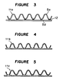
- Figs. 3 to 5 are diagrams illustrating the effect of an adhesive.
- Figs. 6 to 8 show a first filter element: Fig. 6 is a front view thereof; Fig. 7 (a) is a left side view thereof; Fig. 7 (b) is a right side view thereof; and Fig. 8 is a longitudinal sectional view thereof.
- Figs. 9 and 10 show a second filter element: Fig. 9 is a perspective view thereof; and Fig. 10 is an exploded perspective view thereof.
- a catalyst carrier was produced by using the elongate dried sheets 5b having a width of 15 cm obtained in Example 1 above.
- the process of producing it is shown in Fig. 2. That is, one of the sheets 5b was molded by gear type presses 9a, 9b into a corrugate sheet 5d having a sine-wave shape with a height of 3 mm, the corrugated sheet 5d and the other flat sheet 5b were bonded together with an adhesive to form a laminate 10a, and the laminate 10a was rolled to form an assembly 10b having a diameter of 14 cm.
- the adhesive that was used was one obtained by adding the same metal powder as above to a commercially available glue in a volume ratio of 0.1 to 1.
- the rolled assembly 10b was sintered in the sintering oven 8 at 1,100°C for 120 min.
- a porous metal catalyst carrier 10c having a cylindrical shape with a length of 11 cm and a diameter of 10 cm and having a thickness of 50 ⁇ m was obtained.
- Fig. 2 one end of the cylinder of the catalyst carrier 10c is shown.
- Figs. 3 to 5 are views illustrating the difference in bonding effect in the case where a metal powder was contained in an adhesive and in the case where a metal powder was not contained in the adhesive.
- the worked item 11a shown in Fig. 3 was obtained by putting together the above flat dried sheet member 5b and a dried sheet member 5d obtained by corrugating a similar flat dried sheet 5b, with an adhesive 12.
- the adhesive 12 was prepared by mixing uniformly a metal powder similar to that contained in the dried sheet member 5a (5b) with a starch glue in a volume ratio of 0.1 to 1.
- Fig. 4 shows a porous sintered metal 11b obtained by subjecting the above worked item 11a to sintering treatment in a sintering oven at 1,200°C for 120 min.
- the dried sheet member 5b which was uniformly joined throughout and the corrugated dried sheet member 5d were integrated.
- the proportion of the metal powder to be contained in the adhesive is not limited to the above ratio and may be in the range of from 0.003 to 0.5 (in the volume ratio) to 1 of the glue.
- the degree of the mixing proportion will be decided depending on the aimed porous metal product or the like.
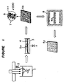
- Figs. 6 to 9 show a filter element 12a according to the first Example of a filter element: Fig. 6 is its front view; Fig. 7(a) is its left side elevational view; Fig. 7(b) is its right side elevational view; and Fig. 8 is its longitudinal sectional view.
- the filter element 12a has a cylindrical shape in appearance and comprises an assembly 14a having a number of porous metal cells 13a, 13a...one end of which is opened and the other end of which is closed.
- the assembly 14a is formed by putting together a dried sheet member 5b as shown in Fig. 2 above, wherein a metal powder is supported, and a dried corrugated sheet member 5d formed by corrugating a dried sheet similar to the first dried sheet 5b and rolling them into a cylinder, and every other alternative honeycomb openings in the opposite end surfaces of the cylinder are cut by scissors and are closed by sticking with a glue containing a metal powder.
- the shaded parts show the closed end wall surfaces. The closing is effected in such a manner that the both opposite ends of each cell 13 are not closed simultaneously. Then the thus formed cylindrical worked item is subjected to sintering treatment to obtain a filter element 12a.
- the size of the openings and the ratio of the openings of the filter element are decided arbitrarily depending on conditions such as the sintering treatment temperature, the heating time, and the particle diameter of the metal powder. For example, even a pore diameter of 30 ⁇ m which is required for eliminating carbonized fine particles from the above exhaust gas can be easily obtained.
- the filter element 12a When the filter element 12a is used for treatment of exhaust gas from an engine, the filter element 12a is loaded in an exhaust gas path 15 of an engine as shown in Fig. 8. Therefore, the exhaust gas passing through the exhaust gas path 15 enters the inside from end surface where cells 13a are open as shown by arrows, flows into adjacent cells 13a through the side walls of the particular cells 13a, and leaves from the openings of the latter cells 13a. Of course, the exhaust gas will pass through the closed ends of the cells 13a 13a...since the closed ends are porous.
- the filter element 12a When the exhaust gas passes through the wall surfaces of the cells 13a, carbonized fine-particles in the exhaust gas are caught on the wall surfaces, and the purified exhaust gas is released into the atmosphere. Since it is possible to allow the filter element 12a to carry a catalyst such as platinum, it can be possible to allow the filter element 12a to serve also as a catalyst converter.
- the wall surfaces of the cells 13a will be clogged with carbonized fine particles. This clogging can be removed by heating the filter element 12a to burn out the carbonized fine particles. That is, since the filter element 12a is metallic and conductive, when an electric current is passed from a power source 16 to the filter element 12a by turning the switch 17 on, the filter element 12a generates heat in proportion to the electric resistance. In other words, the filter element 12a acts as an electric heater to burn out the carbonized fine particles.
- the electric resistance of the filter element 12a is decided arbitrarily by choosing the type of the metal powder contained in the dried sheet member. In the case of a metal powder high in electric resistance such as nickel or chromium powder, heat can be generated efficiently.
- the filter element 12a according to this Example is an assembly of porous metal cells whose adjacent ends are alternatively opened and closed, the filtering area can be made large, and when the filter element 12a is placed in an exhaust system of an engine, carbonized fine particles can be effectively eliminated.
- the carbonized fine particles caught by the filter element 12a are burnt by causing the filter element 12a to act as an electric heater, so that the filter element can be regenerated.
- Figs. 9 and 10 show the filter element 12b according to the second Example of a filter element; Fig. 9 shows its perspective view; and Fig. 10 is its exploded perspective view.
- the filter element 12b comprises an assembled body 14b of porous metal cells 13b, 13b...in the shape of a polygonal tube and is generally in the shape of a prism.
- the shaded sections in Fig. 9 are closed end walls of the cells 13b, and in the same manner as in the first filter element 12a, the ends of the adjacent cells are alternatively closed and opened.
- the filter element 12b of this Example is produced by associating four types of dried sheets containing a metal powder as shown in Figs. 10(a) to (d) to form an assembly 14b and subjecting it to sintering treatment.
- flat dried sheet members 20a having the same shape as that of the upper surface of the assembly 14b as shown in Fig. 10(a) and corrugated sheets 20b that are obtained by corrugating flat dried sheet members similar to the sheet members 20a and that have length and breadth dimensions in conformity with the dried sheet members 20a are alternatively laid and bonded with an adhesive containing a metal powder. Dried sheet members 20a are bonded also to the top and bottom corrugated sheets 20b.
- Side plates 20c and 20d made of dried sheet members similar to the above dried sheets and having openings with a prescribed interval between them as shown in Figs. 10(c) and (d) are bonded to the left and right ends of the above laminate with the adhesive containing a powder metal.
- the positional relationship of the openings of the side plates 20c and 20d is such that the openings of the cells 13b on the one side of the assembly 14b are alternatively opened and closed and the openings of the particular cells 13b on the other side of the assembly 14b are alternatively closed and opened so that one end of the cells 13b may be opened and the opposite end of the cells 13b may be closed.
- the thus obtained assembly 14b is subjected to sintering treatment, and the fibrous substance is burned away by the sintering treatment and a sintered metal is formed from the remaining metal power.
- the sintered metal product is a porous metal product having the original shape retained and has a function as a filter element. Therefore this filter element 12b can filter carbonized fine particles in exhaust gas in the same way as the above first filter element 12a, and the carbonized fine particles can be burnt and removed by allowing the filter element 12b to act as an electric heater.
- the openings of the cells may not always be completely alternatively closed and opened but may be arranged in a scattered manner if the same filtering effect is obtained.
- the filter element is used for treating gasses, it may be used for treating liquids of course.
- the assembly 14b is formed without the side plates 20c and 20d and the assembly 14b is subjected to sintering treatment, the both opposite ends of the cells 13b are opened and it can be used as a catalyst carrier.
- a porous metal product having that shape Before sintering treatment, by working the shape of a dried sheet into the shape of the final product, for example, a complicated shape such as a folded crane, a catalyst carrier or a filter element, a porous metal product having that shape can be obtained. When dried sheets are twisted together, a threadlike porous metal product can be obtained.
- the adhesive used in the production of an item contains the same metal powder as that contained in the sheet member, even if the sheet members are not joined firmly, the sections bonded with the adhesive can be joined uniformly after sintering treatment.
- the catalyst carrier is obtained by subjecting a mixture of a metal powder and a fibrous substance to sintering treatment, the catalyst carrier can be molded into a porous metal catalyst carrier having a quite large surface area. Further, the catalyst carrier can be made as a tough catalyst carrier having a honeycomb structure.
- the filter element comprises an assembly having porous metal cells whose ends are alternatively opened and closed or are opened and closed in a scattered manner, the filtering area can be made large, and when the filter element is placed in an exhaust system of an engine, carbonized fine particles in exhaust gas can be eliminated efficiently.
Landscapes
- Chemical & Material Sciences (AREA)
- Engineering & Computer Science (AREA)
- Chemical Kinetics & Catalysis (AREA)
- Mechanical Engineering (AREA)
- Combustion & Propulsion (AREA)
- General Engineering & Computer Science (AREA)
- Health & Medical Sciences (AREA)
- Toxicology (AREA)
- Manufacturing & Machinery (AREA)
- Inorganic Chemistry (AREA)
- Life Sciences & Earth Sciences (AREA)
- Geology (AREA)
- Materials Engineering (AREA)
- Organic Chemistry (AREA)
- Catalysts (AREA)
- Powder Metallurgy (AREA)
Abstract
Description
- The present invention relates to a method of producing a porous metal and a metal product using the same such as a catalyst carrier and a filter element.
- Conventionally, in order to make NOx or the like contained in exhaust gas from engines nontoxic, use is made of catalyst converters using platinum as a catalyst. As the carrier for supporting the catalyst, ceramics and metal plates that are molded into a honeycomb structure are known.
- Ceramic catalyst carriers are obtained by molding a raw material into a honeycomb structure and baking it. Also, catalyst carriers made of metal plates are constructed by placing a corrugated metal band and a flat metal band one over the other and rolling them as disclosed, for example, in Japanese Unexamined Patent Publication No. 71547/1987.
- Also, the tendency of desire for cleaning the environment has recently increased, and it is even desired to eliminate black smoke released from engines, particularly from diesel engines that use light oil as fuel. The black smoke is composed of carbonized fine particles. Therefore, it is possible to eliminate them by a filter element having openings smaller than the particle diameter.
- However, since the above catalyst converter does not have any filtering function, it cannot be used to treat black smoke simultaneously with the treatment of gases such as NOx. If the catalyst converter is made to have a filtering function, clogging will take place immediately, and as a result not only the function of the catalyst converter itself lowers but also the exhaust system of the engine is choked thereby causing the ability of the engine itself to lower.
- As filter elements having openings smaller than the above carbonized fine particles, those made of a porous sintered metal or ceramic are known. The known filter elements are used in food manufacturing processes and other manufacturing processes.
- However, the above ceramic catalyst carrier is attended with drawbacks that it is weak in impact and is liable to be broken.
- The above metal plate catalyst carrier has a drawback that the cost is high because adjacent parts of the two metal plates are needed to be welded and a large-sized press apparatus is needed for corrugating a metal band. Further, the Fe-Al metal used in the catalyst carrier involves a manufacturing problem that it is difficult to roll.
- It is impossible to arrange the above known filter element in a limited space such as the exhaust system of an engine with the filtering area made large. This is because the known filter element only has a flat filtering surface or at most only has a single cylindrical shape.
- Further, a filter element used in the exhaust system of an engine must be one that can be easily regenerated. If the filter element cannot be regenerated and is replaced at every time of its clogging, not only the cost becomes so high that it cannot be adopted but also a problem that replacing work is needed arises.
- The present invention has been made to overcome the above problems and a first object of the present invention is to provide a method of producing a porous metal suitable for catalyst carriers and filter elements without requiring a large-scale manufacturing apparatus such as a rolling mill.
- Another object of the present invention is to provide inexpensive and tough catalyst carrier and filter element made of a porous metal.
- A still another object of the present invention is to provide a filter element that can be readily regenerated.
- The method of producing a porous metal according to the present invention is given in claim 1.
- The fibrous substance indicated in claim 1 may comprise pulp.
- The mixture indicated in claim 1 comprises one obtained by mixing and stirring a metal powder and a fibrous substance in water and subjecting the mixture to dehydration and drying treatment.
- Said mixture is comprises a dried sheet obtained by mixing and stirring a metal powder and a fibrous substance in water, removing water from the mixture by a screen to form a sheet, and subjecting the sheet to drying treatment.
- Said dried sheet is worked into the shape of a catalyst carrier, a filter element or the like and the worked item is subjected to sintering treatment.
- The working of the worked item into the shape of a catalyst carrier, a filter element or the like is carried out by using an adhesive containing a metal powder.
- The catalyst carrier as given in
claim 4 is obtained by laminating a dried sheet wherein a metal powder is supported in a fibrous substance with a dried sheet obtained by corrugating a dried sheet similar to the first-mentioned sheet to form an assembly of a number of cells having both opposite ends opened and subjecting the assembly of cells to sintering treatment. - The assembly of cells is formed by laminating a dried sheet with a corrugated dried sheet and rolling the laminate.
- The filter element as given in
claim 6 is obtained by laminating a dried sheet wherein a metal powder is supported in a fibrous substance and a dried sheet obtained by corrugating a dried sheet similar to the first-mentioned sheet to form an assembly of a number of cells whose one end is opened and whose other end is closed and subjecting the assembly to sintering treatment. - Said assembly of cells comprises one obtained by laminating a dried sheet and a corrugated dried sheet and rolling the laminate.
- Said filter element is provided with electric current applying means.
- As the metal powder, any powder of an iron or non-iron type metal such as iron, copper, aluminum, gold, and silver or an alloy may be used, and the type of the metal powder is not restricted if it can be subjected to sintering treatment. Further, a mixture of two or more metal powders may be used.
- The type of metal powder to be used will be decided depending on the application of the final product. For example, if the final product is a decorative article made of a noble metal, a noble metal powder such as gold powder or silver powder is used, while if the final product is used as a filter element or a catalyst carrier for treating exhaust gas from engines, an Fe-Al type powder is used.
- As the fibrous substance, any of natural fibers or synthetic fibers can be used if it can support the metal powder and can be burnt out when subjected to sintering treatment. Pulp is particularly preferably used since it is inexpensive and readily available.
- For the sintering treatment, a known sintering oven used in powder metallurgy or the like can be employed. It is not required particularly to compress the material as known powder metallurgy.
- The sintering temperature is decided depending on the type of the metal powder and the particle diameter of the metal powder. For example, the sintering temperature is from 1,100 to 1,250°C for Fe powder.
- The mixture of a metal powder and a fibrous substance is obtained in the presence of water. That is, the mixture is obtained by placing a metal powder, a fibrous substance, and water in a tank and mixing and stirring them by an agitator.
- The mixing ratio of the thus obtained mixture (slurry) will be decided depending on the use of the final product, that is, depending on the thickness of the final product and the proportion of the openings of the porous metal.
- When the slurry is produced, a polymer flocculant is added, by which the metal powder can be supported uniformly on the fibrous substance.
- As the polymer flocculant to be added, a cationic or anionic flocculant is selected depending the type of the metal powder and the type of the fibrous substance and the amount of the polymer flocculant to be added is suitably selected depending, for example, on the the type of the fibrous substance and the metal powder. If the fibrous substance is a synthetic fibrous substance, some types of the fibrous substances do not require the addition of a polymer flocculant. Therefore the addition of a polymer flocculant is not an essential requirement.
- The slurry is dehydrated by a screen. That is, the slurry is dehydrated according to the principle known in paper making and is formed into a sheet. With respect to the openings of the screen used, it is enough if they can catch most of the fibrous substance and those having a size of from 60 to 100 meshes can be used. The sheet can be formed into the shape of a band by constructing the screen into an endless belt as is known in a paper making machine.
- The sheet formed on a screen is dehydrated by solar drying or forced drying. Since the sheet that has been dried (dried sheet) has a shape and properties similar to common papers, the sheet can be worked, for example, cut, folded, bent, or stuck like common papers.
- The thickness of the dried sheet will be decided taking the thickness of the final product into consideration. That is, since the dried sheet shrinks to a certain degree, when subjected to sintering treatment, depending on the type of the fibrous substance, the type of the metal powder, the mixing ratio of them, and the sintering temperature, the thickness of the dried sheet is decided taking this degree of shrinkage into account. Similarly, the outer shape of the dried sheet is also decided taking the degree of shrinkage into account.
- Fig. 1 is a flow sheet showing an example for carrying out the present method.
- Fig. 2 is a flow chart showing an example for producing a catalyst carrier.
- Figs. 3 to 5 are diagrams illustrating the effect of an adhesive.
- Figs. 6 to 8 show a first filter element: Fig. 6 is a front view thereof; Fig. 7 (a) is a left side view thereof; Fig. 7 (b) is a right side view thereof; and Fig. 8 is a longitudinal sectional view thereof.
- Figs. 9 and 10 show a second filter element: Fig. 9 is a perspective view thereof; and Fig. 10 is an exploded perspective view thereof.
-
- (1) A porous metal product was obtained by following the flow sheet shown in Fig. 1.
First, 1163 mℓ of water was placed in the tank 1, then 6.25 g of a metal powder of pure iron having an average particle diameter of 2.7 µm and 3.125 g of pulp (a 8:2 mixture of NBKP and LBKP) were added thereto, and after 0.94 × 10⁻² g of a polymer flocculant(Hiholder 936 manufactured by Kurita Kogyo KK) was added, they were mixed and stirred by an agitator 2 thereby obtaining a slurry.
The slurry was transferred into acontainer 3 and was screened through a 80-mesh screen 4 in the same way as in paper making to obtain asheet 5a.
Thesheet 5a was forcibly dried by warm air. The driedsheet 5b had a thickness of from 120 to 130 µm.
In Fig. 1, (a) shows the state of the driedsheet 5b which is magnified 1000 times, from which it can be understood that themetal powder 7 is supported uniformly in thepulp 6.
When the polymer flocculant was not added, themetal powder 7 supported by thepulp 6 was scattered unevenly and after the sintering treatment, a desired porous metal product in the form of a sheet could not be obtained.
The driedsheet 5b was sintered by heating it in asintering oven 8 at 1,100°C for 120 min. Thus, aporous metal product 5c in the form of a sheet having a thickness of 50 µm was obtained.
When the sintering temperature was 1,200°C, the porousness disappeared, and a flat platelike metal product was obtained. - (2) The dried
sheet 5b obtained as above was cut into squares, the square sheet was folded to form a folded crane, and when the folded crane was subjected to sintering treatment in thesintering oven 8 for 120 min, a porous metal product was obtained with the original shape of the folded crane almost kept. The porous metal product, i.e., a folded crane had a value enough as a decorative article. - A catalyst carrier was produced by using the elongate dried
sheets 5b having a width of 15 cm obtained in Example 1 above. The process of producing it is shown in Fig. 2. That is, one of thesheets 5b was molded by gear type presses 9a, 9b into acorrugate sheet 5d having a sine-wave shape with a height of 3 mm, thecorrugated sheet 5d and the otherflat sheet 5b were bonded together with an adhesive to form a laminate 10a, and the laminate 10a was rolled to form anassembly 10b having a diameter of 14 cm. The adhesive that was used was one obtained by adding the same metal powder as above to a commercially available glue in a volume ratio of 0.1 to 1. - The rolled
assembly 10b was sintered in thesintering oven 8 at 1,100°C for 120 min. Thus, a porousmetal catalyst carrier 10c having a cylindrical shape with a length of 11 cm and a diameter of 10 cm and having a thickness of 50 µm was obtained. In Fig. 2, one end of the cylinder of thecatalyst carrier 10c is shown. - It is important that an adhesive containing a metal powder is used when the dried
sheet member 5b is shaped into an intended porous metal product. - Figs. 3 to 5 are views illustrating the difference in bonding effect in the case where a metal powder was contained in an adhesive and in the case where a metal powder was not contained in the adhesive.
- The worked
item 11a shown in Fig. 3 was obtained by putting together the above flat driedsheet member 5b and a driedsheet member 5d obtained by corrugating a similar flatdried sheet 5b, with an adhesive 12. The adhesive 12 was prepared by mixing uniformly a metal powder similar to that contained in the driedsheet member 5a (5b) with a starch glue in a volume ratio of 0.1 to 1. - Fig. 4 shows a porous
sintered metal 11b obtained by subjecting the above workeditem 11a to sintering treatment in a sintering oven at 1,200°C for 120 min. At the joined sections of the obtained porous sintered metal, the driedsheet member 5b which was uniformly joined throughout and the corrugated driedsheet member 5d were integrated. - In contrast, in the case wherein a worked
item 11c was prepared by using an adhesive containing no metal powder in a starch glue and was subjected to sintering treatment under the same conditions as above, the joined sections after the sintering treatment did not give a satisfactory joined state as shown in Fig. 5. - The proportion of the metal powder to be contained in the adhesive is not limited to the above ratio and may be in the range of from 0.003 to 0.5 (in the volume ratio) to 1 of the glue. The degree of the mixing proportion will be decided depending on the aimed porous metal product or the like.
- A filter element according to the present invention will now be described with reference to Figs. 6 to 10.
- Figs. 6 to 9 show a
filter element 12a according to the first Example of a filter element: Fig. 6 is its front view; Fig. 7(a) is its left side elevational view; Fig. 7(b) is its right side elevational view; and Fig. 8 is its longitudinal sectional view. - The
filter element 12a has a cylindrical shape in appearance and comprises anassembly 14a having a number ofporous metal cells assembly 14a is formed by putting together a driedsheet member 5b as shown in Fig. 2 above, wherein a metal powder is supported, and a driedcorrugated sheet member 5d formed by corrugating a dried sheet similar to the first driedsheet 5b and rolling them into a cylinder, and every other alternative honeycomb openings in the opposite end surfaces of the cylinder are cut by scissors and are closed by sticking with a glue containing a metal powder. In Figs. 7(a) and 7(b), the shaded parts show the closed end wall surfaces. The closing is effected in such a manner that the both opposite ends of eachcell 13 are not closed simultaneously. Then the thus formed cylindrical worked item is subjected to sintering treatment to obtain afilter element 12a. - The size of the openings and the ratio of the openings of the filter element are decided arbitrarily depending on conditions such as the sintering treatment temperature, the heating time, and the particle diameter of the metal powder. For example, even a pore diameter of 30 µm which is required for eliminating carbonized fine particles from the above exhaust gas can be easily obtained.
- When the
filter element 12a is used for treatment of exhaust gas from an engine, thefilter element 12a is loaded in anexhaust gas path 15 of an engine as shown in Fig. 8. Therefore, the exhaust gas passing through theexhaust gas path 15 enters the inside from end surface wherecells 13a are open as shown by arrows, flows intoadjacent cells 13a through the side walls of theparticular cells 13a, and leaves from the openings of thelatter cells 13a. Of course, the exhaust gas will pass through the closed ends of thecells 13a - When the exhaust gas passes through the wall surfaces of the
cells 13a, carbonized fine-particles in the exhaust gas are caught on the wall surfaces, and the purified exhaust gas is released into the atmosphere. Since it is possible to allow thefilter element 12a to carry a catalyst such as platinum, it can be possible to allow thefilter element 12a to serve also as a catalyst converter. - When the treatment of exhaust gas is continued, the wall surfaces of the
cells 13a will be clogged with carbonized fine particles. This clogging can be removed by heating thefilter element 12a to burn out the carbonized fine particles. That is, since thefilter element 12a is metallic and conductive, when an electric current is passed from apower source 16 to thefilter element 12a by turning theswitch 17 on, thefilter element 12a generates heat in proportion to the electric resistance. In other words, thefilter element 12a acts as an electric heater to burn out the carbonized fine particles. - The electric resistance of the
filter element 12a is decided arbitrarily by choosing the type of the metal powder contained in the dried sheet member. In the case of a metal powder high in electric resistance such as nickel or chromium powder, heat can be generated efficiently. - Since the
filter element 12a according to this Example is an assembly of porous metal cells whose adjacent ends are alternatively opened and closed, the filtering area can be made large, and when thefilter element 12a is placed in an exhaust system of an engine, carbonized fine particles can be effectively eliminated. - The carbonized fine particles caught by the
filter element 12a are burnt by causing thefilter element 12a to act as an electric heater, so that the filter element can be regenerated. - Figs. 9 and 10 show the filter element 12b according to the second Example of a filter element; Fig. 9 shows its perspective view; and Fig. 10 is its exploded perspective view.
- The filter element 12b comprises an assembled body 14b of
porous metal cells cells 13b, and in the same manner as in thefirst filter element 12a, the ends of the adjacent cells are alternatively closed and opened. - The filter element 12b of this Example is produced by associating four types of dried sheets containing a metal powder as shown in Figs. 10(a) to (d) to form an assembly 14b and subjecting it to sintering treatment.
- That is, flat dried
sheet members 20a having the same shape as that of the upper surface of the assembly 14b as shown in Fig. 10(a) andcorrugated sheets 20b that are obtained by corrugating flat dried sheet members similar to thesheet members 20a and that have length and breadth dimensions in conformity with the driedsheet members 20a are alternatively laid and bonded with an adhesive containing a metal powder. Driedsheet members 20a are bonded also to the top and bottomcorrugated sheets 20b. -
Side plates side plates cells 13b on the one side of the assembly 14b are alternatively opened and closed and the openings of theparticular cells 13b on the other side of the assembly 14b are alternatively closed and opened so that one end of thecells 13b may be opened and the opposite end of thecells 13b may be closed. - The thus obtained assembly 14b is subjected to sintering treatment, and the fibrous substance is burned away by the sintering treatment and a sintered metal is formed from the remaining metal power. The sintered metal product is a porous metal product having the original shape retained and has a function as a filter element. Therefore this filter element 12b can filter carbonized fine particles in exhaust gas in the same way as the above
first filter element 12a, and the carbonized fine particles can be burnt and removed by allowing the filter element 12b to act as an electric heater. - In this connection, the openings of the cells may not always be completely alternatively closed and opened but may be arranged in a scattered manner if the same filtering effect is obtained.
- In the above case, although the filter element is used for treating gasses, it may be used for treating liquids of course.
- Further, if the assembly 14b is formed without the
side plates cells 13b are opened and it can be used as a catalyst carrier. - Since a metal powder is supported in a fibrous substance and is subjected to sintering treatment to mold the metal, a porous metal item can be quite easily obtained.
- When the fibrous substance is pulp, a porous metal item can be obtained quite inexpensively.
- Further, when a fibrous substance supporting a metal is made into a sheet in the way as used in paper making and the sheet is subjected to sintering treatment, a porous metal molded item that is in the shape of a quite thin sheet or band can be obtained.
- Before sintering treatment, by working the shape of a dried sheet into the shape of the final product, for example, a complicated shape such as a folded crane, a catalyst carrier or a filter element, a porous metal product having that shape can be obtained. When dried sheets are twisted together, a threadlike porous metal product can be obtained.
- Since the adhesive used in the production of an item contains the same metal powder as that contained in the sheet member, even if the sheet members are not joined firmly, the sections bonded with the adhesive can be joined uniformly after sintering treatment.
- Since the catalyst carrier is obtained by subjecting a mixture of a metal powder and a fibrous substance to sintering treatment, the catalyst carrier can be molded into a porous metal catalyst carrier having a quite large surface area. Further, the catalyst carrier can be made as a tough catalyst carrier having a honeycomb structure.
- Since the filter element comprises an assembly having porous metal cells whose ends are alternatively opened and closed or are opened and closed in a scattered manner, the filtering area can be made large, and when the filter element is placed in an exhaust system of an engine, carbonized fine particles in exhaust gas can be eliminated efficiently.
Claims (8)
- A method of producing a porous metal product, comprising the steps of:
forming a mixture of a metal powder and a fibrous substance in water;
removing water from the mixture by a screen to form first and second sheets,
subjecting the sheets to a drying treatment;
bonding said first dried sheet from said drying step to the second dried sheet from said drying step to form a laminate sheet by using an adhesive comprising a metal powder that is the same as the metal powder used to form the mixture;
working said laminate sheet into the shape of a final product of a decorative article, a catalyst carrier or a filter element; and
subjecting said worked laminate sheet to a sintering treatment. - The method of producing a porous metal product according to Claim 1, wherein said fibrous substance comprises pulp.
- The method of producing a porous metal product according to Claim 1 or 2, wherein said dried sheet is worked into the shape of a catalyst carrier or a filter element and the worked item is subjected to sintering treatment.
- A catalyst carrier comprising an assembly of a number of cells having both ends opened, wherein said assembly of cells is obtained by laminating a dried sheet wherein a metal powder is supported in a fibrous substance with a dried sheet obtained by corrugating a dried sheet similar to the first-mentioned dried sheet by using an adhesive containing a metal powder and subjecting the laminated assembly to sintering treatment to burn off the fibrous substance and to sinter the metal powder contained in the dried sheets and the adhesive .
- The catalyst carrier according to Claim 4, wherein said assembly of cells is obtained by laminating a dried sheet with a corrugated dried sheet to form a monolayer laminate by using an adhesive containing a metal powder, rolling the laminate into a spiral cylinder shape and subjecting the rolled laminate to sintering treatment.
- A filter element comprising an assembly of a number of calls having one end opened and having the other end closed, wherein said assembly of cells is obtained by laminating a dried sheet wherein a metal powder is supported in a fibrous substance with a dried sheet obtained by corrugating a dried sheet similar to the first-mentioned dried sheet by using an adhesive containing a metal powder and subjecting the laminated assembly to sintering treatment to burn off the fibrous substance and to sinter the metal powder contained in the dried sheets and the adhesive.
- The filter element according to Claim 6, wherein said assembly of cells is obtained by laminating a dried sheet with a corrugated dried sheet to form a monolayer laminate by using an adhesive containing a metal powder, rolling the laminate into a spiral cylinder shape and subjecting the rolled laminate to sintering treatment.
- The filter element according to Claim 6 or 7, wherein said filter element is provided with electric current applying means.
Applications Claiming Priority (4)
| Application Number | Priority Date | Filing Date | Title |
|---|---|---|---|
| JP299634/90 | 1990-11-05 | ||
| JP2299634A JPH04171014A (en) | 1990-11-05 | 1990-11-05 | Filter element |
| JP29963590A JPH04173905A (en) | 1990-11-05 | 1990-11-05 | Adhesive for sintered metal |
| JP299635/90 | 1990-11-05 |
Publications (2)
| Publication Number | Publication Date |
|---|---|
| EP0484593A1 EP0484593A1 (en) | 1992-05-13 |
| EP0484593B1 true EP0484593B1 (en) | 1996-06-19 |
Family
ID=26562012
Family Applications (1)
| Application Number | Title | Priority Date | Filing Date |
|---|---|---|---|
| EP90124791A Expired - Lifetime EP0484593B1 (en) | 1990-11-05 | 1990-12-19 | Method of producing a porous metal and a metal product using the same such as a catalyst carrier |
Country Status (6)
| Country | Link |
|---|---|
| US (1) | US5174951A (en) |
| EP (1) | EP0484593B1 (en) |
| AT (1) | ATE139471T1 (en) |
| AU (1) | AU640722B2 (en) |
| CA (1) | CA2032932C (en) |
| DE (1) | DE69027532T2 (en) |
Families Citing this family (6)
| Publication number | Priority date | Publication date | Assignee | Title |
|---|---|---|---|---|
| JP2707049B2 (en) * | 1993-12-09 | 1998-01-28 | 株式会社いすゞセラミックス研究所 | Diesel particulate filter |
| US5592686A (en) * | 1995-07-25 | 1997-01-07 | Third; Christine E. | Porous metal structures and processes for their production |
| EP0853601A1 (en) * | 1995-10-06 | 1998-07-22 | Lanxide Technology Company, Lp | Thin ceramic composite bodies and methods for making the same |
| DE19832625C2 (en) * | 1998-07-21 | 2001-05-17 | Xcellsis Gmbh | Process for producing a stacked reactor and stacked reactor for generating hydrogen from hydrocarbons |
| DE102004035311A1 (en) * | 2004-07-21 | 2006-02-16 | Robert Bosch Gmbh | Method for producing at least one region of a filter structure, in particular for a particle filter in the exhaust system of an internal combustion engine |
| TW200927463A (en) * | 2007-12-26 | 2009-07-01 | Jiun-Guang Luo | Ant nest-like connection scaffold structure, method of manufacturing the same, ant nest-like connection scaffold structure device and its manufacturing method |
Family Cites Families (18)
| Publication number | Priority date | Publication date | Assignee | Title |
|---|---|---|---|---|
| US2970905A (en) * | 1957-09-18 | 1961-02-07 | Haller Inc | Method of making a composite sintered powdered material article |
| GB922599A (en) * | 1960-03-11 | 1963-04-03 | Ici Ltd | Methods of manufacturing electrodes |
| FR1307084A (en) * | 1961-11-29 | 1962-10-19 | Gen Electric | Laminated metal foams and process for preparing them |
| US3409473A (en) * | 1962-08-13 | 1968-11-05 | Clevite Corp | Porous plate and method of making same |
| US3454396A (en) * | 1964-07-09 | 1969-07-08 | Minnesota Mining & Mfg | Fuel elements |
| GB1263696A (en) * | 1968-04-16 | 1972-02-16 | British Ropes Ltd | Improvements in or relating to the manufacture of sheets of sintered material |
| US3887365A (en) * | 1971-03-24 | 1975-06-03 | Nasa | Process for making sheets with parallel pores of uniform size |
| US4017570A (en) * | 1971-04-05 | 1977-04-12 | Chemotronics International, Inc. | Method of producing three dimensional skeletal structures |
| JPS4948060B1 (en) * | 1971-04-27 | 1974-12-19 | ||
| FR2521887A1 (en) * | 1982-02-24 | 1983-08-26 | Comp Generale Electricite | PROCESS FOR PREPARING A POROUS METAL BODY |
| JPS58213684A (en) * | 1982-06-02 | 1983-12-12 | 凸版印刷株式会社 | Manufacture of laminate ceramic body |
| US4562039A (en) * | 1984-06-27 | 1985-12-31 | Pall Corporation | Porous metal article and method of making |
| US4613369A (en) * | 1984-06-27 | 1986-09-23 | Pall Corporation | Porous metal article and method of making |
| US4729871A (en) * | 1985-06-21 | 1988-03-08 | Hiroshi Kawaguchi | Process for preparing porous metal plate |
| JPS62154572A (en) * | 1985-12-27 | 1987-07-09 | Fuji Electric Corp Res & Dev Ltd | Manufacture of molten carbonate fuel cell |
| US4722824A (en) * | 1986-06-04 | 1988-02-02 | Fine Particle Technology Corp. | Method of joining green bodies prior to sintering |
| JPS63171802A (en) * | 1987-01-08 | 1988-07-15 | Kobe Steel Ltd | Prodoction of porous sintered metallic body |
| US4780437A (en) * | 1987-02-11 | 1988-10-25 | The United States Of America As Represented By The United States Department Of Energy | Fabrication of catalytic electrodes for molten carbonate fuel cells |
-
1990
- 1990-12-18 AU AU68206/90A patent/AU640722B2/en not_active Ceased
- 1990-12-19 AT AT90124791T patent/ATE139471T1/en not_active IP Right Cessation
- 1990-12-19 DE DE69027532T patent/DE69027532T2/en not_active Expired - Fee Related
- 1990-12-19 EP EP90124791A patent/EP0484593B1/en not_active Expired - Lifetime
- 1990-12-21 US US07/631,875 patent/US5174951A/en not_active Expired - Fee Related
- 1990-12-21 CA CA002032932A patent/CA2032932C/en not_active Expired - Fee Related
Also Published As
| Publication number | Publication date |
|---|---|
| DE69027532D1 (en) | 1996-07-25 |
| CA2032932A1 (en) | 1992-05-06 |
| CA2032932C (en) | 1999-05-25 |
| US5174951A (en) | 1992-12-29 |
| AU640722B2 (en) | 1993-09-02 |
| EP0484593A1 (en) | 1992-05-13 |
| AU6820690A (en) | 1992-06-04 |
| DE69027532T2 (en) | 1996-12-19 |
| ATE139471T1 (en) | 1996-07-15 |
Similar Documents
| Publication | Publication Date | Title |
|---|---|---|
| US5194078A (en) | Exhaust filter element and exhaust gas-treating apparatus | |
| EP0087067A1 (en) | Exhaust gas filter and method of making the same | |
| DE3332345C2 (en) | Filter material made of metal mesh | |
| DE69937730T2 (en) | METAL FILTER | |
| EP0484593B1 (en) | Method of producing a porous metal and a metal product using the same such as a catalyst carrier | |
| DE3818281A1 (en) | EXHAUST FILTER | |
| EP0373648B1 (en) | Catalytic composite on delafosite basis for purifying exhaust gases and a method for preparing the same | |
| KR20010022633A (en) | Production of composite porous fibre structures | |
| JPH0372907A (en) | Manufacturing process of filter, and filter | |
| US20030209488A1 (en) | Ceramic fiber-based filter web and method | |
| AU624037B2 (en) | Exhaust filter element and exhaust gas-treating apparatus | |
| KR910018080A (en) | Heat-resistant metal monolith and manufacturing method thereof | |
| EP0410200A1 (en) | Porous body for the treatment of gases and/or vapours and/or liquids and process for the production thereof | |
| CN102316956A (en) | Method for producing a ceramic filter element and filter element | |
| US5599360A (en) | Method for the manufacture of char-containing articles | |
| NL9102117A (en) | Porous metal-containing laminate and method for its production | |
| DE2202152C3 (en) | Process for the production of a catalyst carrier for the detoxification of exhaust gases | |
| JPH0328301A (en) | Method for compacting metal | |
| US20030012676A1 (en) | Formed membrane and method of making | |
| DE10329229B3 (en) | Flat membrane stack and method for producing such | |
| JPS648568B2 (en) | ||
| JPH04171014A (en) | Filter element | |
| JPS58223420A (en) | Manufacture of filter element made of ceramic fiber | |
| JPH02164455A (en) | Exhaust gas purifying catalyst | |
| JPS61168582A (en) | Manufacture of inorganic formed body |
Legal Events
| Date | Code | Title | Description |
|---|---|---|---|
| PUAI | Public reference made under article 153(3) epc to a published international application that has entered the european phase |
Free format text: ORIGINAL CODE: 0009012 |
|
| AK | Designated contracting states |
Kind code of ref document: A1 Designated state(s): AT BE CH DE DK ES FR GB GR IT LI LU NL SE |
|
| 17P | Request for examination filed |
Effective date: 19920925 |
|
| 17Q | First examination report despatched |
Effective date: 19940411 |
|
| GRAH | Despatch of communication of intention to grant a patent |
Free format text: ORIGINAL CODE: EPIDOS IGRA |
|
| GRAH | Despatch of communication of intention to grant a patent |
Free format text: ORIGINAL CODE: EPIDOS IGRA |
|
| GRAA | (expected) grant |
Free format text: ORIGINAL CODE: 0009210 |
|
| AK | Designated contracting states |
Kind code of ref document: B1 Designated state(s): AT BE CH DE DK ES FR GB GR IT LI LU NL SE |
|
| PG25 | Lapsed in a contracting state [announced via postgrant information from national office to epo] |
Ref country code: NL Free format text: LAPSE BECAUSE OF FAILURE TO SUBMIT A TRANSLATION OF THE DESCRIPTION OR TO PAY THE FEE WITHIN THE PRESCRIBED TIME-LIMIT Effective date: 19960619 Ref country code: LI Effective date: 19960619 Ref country code: GR Free format text: LAPSE BECAUSE OF FAILURE TO SUBMIT A TRANSLATION OF THE DESCRIPTION OR TO PAY THE FEE WITHIN THE PRESCRIBED TIME-LIMIT Effective date: 19960619 Ref country code: ES Free format text: THE PATENT HAS BEEN ANNULLED BY A DECISION OF A NATIONAL AUTHORITY Effective date: 19960619 Ref country code: DK Effective date: 19960619 Ref country code: CH Effective date: 19960619 Ref country code: BE Effective date: 19960619 Ref country code: AT Effective date: 19960619 |
|
| REF | Corresponds to: |
Ref document number: 139471 Country of ref document: AT Date of ref document: 19960715 Kind code of ref document: T |
|
| ITF | It: translation for a ep patent filed |
Owner name: ING. A. GIAMBROCONO & C. S.R.L. |
|
| REF | Corresponds to: |
Ref document number: 69027532 Country of ref document: DE Date of ref document: 19960725 |
|
| ET | Fr: translation filed | ||
| PG25 | Lapsed in a contracting state [announced via postgrant information from national office to epo] |
Ref country code: SE Effective date: 19960919 |
|
| NLV1 | Nl: lapsed or annulled due to failure to fulfill the requirements of art. 29p and 29m of the patents act | ||
| PG25 | Lapsed in a contracting state [announced via postgrant information from national office to epo] |
Ref country code: LU Free format text: LAPSE BECAUSE OF NON-PAYMENT OF DUE FEES Effective date: 19961231 |
|
| REG | Reference to a national code |
Ref country code: CH Ref legal event code: PL |
|
| PLBE | No opposition filed within time limit |
Free format text: ORIGINAL CODE: 0009261 |
|
| STAA | Information on the status of an ep patent application or granted ep patent |
Free format text: STATUS: NO OPPOSITION FILED WITHIN TIME LIMIT |
|
| 26N | No opposition filed | ||
| PGFP | Annual fee paid to national office [announced via postgrant information from national office to epo] |
Ref country code: DE Payment date: 20011211 Year of fee payment: 12 |
|
| PGFP | Annual fee paid to national office [announced via postgrant information from national office to epo] |
Ref country code: FR Payment date: 20011212 Year of fee payment: 12 |
|
| PGFP | Annual fee paid to national office [announced via postgrant information from national office to epo] |
Ref country code: GB Payment date: 20011219 Year of fee payment: 12 |
|
| REG | Reference to a national code |
Ref country code: GB Ref legal event code: IF02 |
|
| PG25 | Lapsed in a contracting state [announced via postgrant information from national office to epo] |
Ref country code: GB Free format text: LAPSE BECAUSE OF NON-PAYMENT OF DUE FEES Effective date: 20021219 |
|
| PG25 | Lapsed in a contracting state [announced via postgrant information from national office to epo] |
Ref country code: DE Free format text: LAPSE BECAUSE OF NON-PAYMENT OF DUE FEES Effective date: 20030701 |
|
| GBPC | Gb: european patent ceased through non-payment of renewal fee |
Effective date: 20021219 |
|
| PG25 | Lapsed in a contracting state [announced via postgrant information from national office to epo] |
Ref country code: FR Free format text: LAPSE BECAUSE OF NON-PAYMENT OF DUE FEES Effective date: 20030901 |
|
| REG | Reference to a national code |
Ref country code: FR Ref legal event code: ST |
|
| PG25 | Lapsed in a contracting state [announced via postgrant information from national office to epo] |
Ref country code: IT Free format text: LAPSE BECAUSE OF NON-PAYMENT OF DUE FEES;WARNING: LAPSES OF ITALIAN PATENTS WITH EFFECTIVE DATE BEFORE 2007 MAY HAVE OCCURRED AT ANY TIME BEFORE 2007. THE CORRECT EFFECTIVE DATE MAY BE DIFFERENT FROM THE ONE RECORDED. Effective date: 20051219 |