EP0484585B1 - Paraglider - Google Patents
Paraglider Download PDFInfo
- Publication number
- EP0484585B1 EP0484585B1 EP90121459A EP90121459A EP0484585B1 EP 0484585 B1 EP0484585 B1 EP 0484585B1 EP 90121459 A EP90121459 A EP 90121459A EP 90121459 A EP90121459 A EP 90121459A EP 0484585 B1 EP0484585 B1 EP 0484585B1
- Authority
- EP
- European Patent Office
- Prior art keywords
- wing
- paraglider
- flattener
- upper side
- lower side
- Prior art date
- Legal status (The legal status is an assumption and is not a legal conclusion. Google has not performed a legal analysis and makes no representation as to the accuracy of the status listed.)
- Expired - Lifetime
Links
- 239000004744 fabric Substances 0.000 claims abstract description 8
- 239000000725 suspension Substances 0.000 claims description 12
- 239000012209 synthetic fiber Substances 0.000 claims description 6
- 229920002994 synthetic fiber Polymers 0.000 claims description 6
- 239000000463 material Substances 0.000 claims description 4
- 230000006866 deterioration Effects 0.000 description 1
- 238000009958 sewing Methods 0.000 description 1
Images


Classifications
-
- B—PERFORMING OPERATIONS; TRANSPORTING
- B64—AIRCRAFT; AVIATION; COSMONAUTICS
- B64D—EQUIPMENT FOR FITTING IN OR TO AIRCRAFT; FLIGHT SUITS; PARACHUTES; ARRANGEMENT OR MOUNTING OF POWER PLANTS OR PROPULSION TRANSMISSIONS IN AIRCRAFT
- B64D17/00—Parachutes
- B64D17/02—Canopy arrangement or construction
- B64D17/025—Canopy arrangement or construction for gliding chutes
Definitions
- the present invention relates to a paraglider which is for gliding in the air and has a wing which is made of a cloth and into which the air is taken through air intake ports to inflate the wing to a proper wing-like form.
- Fig. 10 is a longitudinally sectional view of a part of a wing 1 of a conventional paraglider.
- Fig. 11 is a cross-sectional view of the wing 1.
- the wing 1 is made of a cloth of synthetic fibers as a whole, and includes an upper side 2, a lower side 3, a plurality of ribs 4 provided between the upper and the lower sides and extending from one of the sides to the other, a plurality of wing chambers 5 defined among the upper and the lower sides and the ribs, and air intake ports provided at the font ends of the wing chambers.
- Each of the ribs 4 has air passage holes 7 through which the mutually adjacent wing chambers 5 communicate with each other. As shown in Fig.
- each of the ribs 4 has a wing-like form for applying a lift to the wing 1.
- each of the ribs 4 has a streamline form slightly convex upward so that the wing chambers 5 generate the wing-like form when air is taken into the chambers through the air intake ports 6.
- Suspension lines 8 are coupled at the upper ends thereof to the bottoms of the ribs 4, and coupled at the lower ends of the lines to the operator of the paraglider through a fitting belt or the like, which is not shown in the drawings.
- the paraglider is of the type in which the suspension lines 8 are coupled to all the ribs 4, there is a paraglider of the other type in which a suspension line is coupled to every other rib. The paraglider of the latter type is used more often than that of the former type.
- the upper and lower sides 2 and 3 of the conventional paraglider are curved convexly upward and downward, respectively, between the ribs 4 at the time of the inflation of the wing 1, a recess 9 is formed in the upper side 2 at the top of the rib and a recess 10 is formed in the lower side 3 at the bottom of the rib, as shown in Fig. 10. Since the ribs 4 are pulled down relative to the other portions of the wing 1 by the suspension lines 8, the recess 9 of the upper side 2 is larger than that 10 of the lower side 3. Because of the recesses 9 and 10, the form of the surface of the wing 1 is unsmooth to make the flow of air on the wing unsmooth.
- the ribs coupled to the suspension lines are pulled down relative to the other portions of the wing of the paraglider of the latter type more than that in the paraglider of the former type to make the recess of the upper side of the wing of the paraglider of the latter type larger than that in the paraglider of the former type to deteriorate the flying performance of the paraglider of the latter type more than that of the paraglider of the former type.
- the present invention was made in order to solve the problem mentioned above. Accordingly, it is an object of the present invention to provide a paraglider, the surface of the wing of which is flattened to achieve the increase in the lift to the wing, the decrease in the resistance thereto, the improvement of the paraglider, the decrease in the dynamic deformation of the wing and so forth so as to enhance the flying performance of the paraglider much more than that of the conventional paraglider.
- the paraglider provided in accordance with the present invention includes the wing made of sheet material and having an upper side, a lower side, a plurality of ribs provided between the upper and the lower sides and extending from one of them to the other, a plurality of wing chambers defined amoung the upper and the lower sides and the ribs, and air intake ports opened into the chambers at the front ends thereof; and suspension lines coupled to some or all of the ribs.
- the paraglider also includes means for coverring recesses made in the upper side or/and the lower side and extending in the front-to-rear direction of the wing.
- the covering means invludes one or more wing flatteners made of sheet material and attached to the upper side and/or the lower side of the wing so as to cover the recesses.
- the paraglider provided in accordance with the present invention flies, air is taken into the wing chambers through the air intake ports to inflate the chambers to spread the wing in a arc-shaped state as a whole.
- the wing flattener is pulled toward both the ends thereof by the upper side or/and the lower side so that the flattener is stretched along the recesses of the upper side or/and the lower side to flatten the surface of the wing.
- FIGs. 1, 2, 3, 4, 5 and 6 show a paraglider which is one of the embodiments.
- a wing flattener 11 nearly shaped as a band and made of a cloth of synthetic fibers is sewn to the wing 1 of the paraglider at and near the front edge of the upper side 2 of the wing along the total length thereof as follows:
- the wing flattener 11 Since the wing flattener 11 is sewn to the wing 1 at the portions (a), (b), (c) and (d) of them so that the flattener covers the recesses 9 of the upper side 2 of the wing, the flattener is stretched along the recesses because of the above-mentioned pulling or the flattener toward the right and left ends thereof by the upper side 2 so that the flattener is separated upward from the tops of the ribs 4 pulled down by the suspension lines 8 of the paraglider, and the surface of the wing is thus flattened at the place of the flattener, as shown in Fig. 1.
- the flow of the air on the upper side 2 of the wing 1 is smoothed to achieve the increase in the lift to the wing, the decrease in the resistance thereto, the improvement of the glide ratio of the paraglider, the decrease in the dynamic deformation of the wing and so forth to enhance the flying performance of the paraglider.
- the wing flattener 11 is provided only at and near the front edge of the upper side 2 of the wing 1 in the embodiment, the flattener may be provided at the other portion of the upper side or at the whole upper side.
- the wing flattener 11 may also be provided at not only the upper side 2 but also the lower side 3, or at only the lower side.
- Fig. 7 shows a part of a paraglider which is another of the embodiments.
- Wing flatteners 11 and 13 are sewn to the upper and lower sides 2 and 3 of the wing of the paraglider at and near the front edges of the sides.
- the manner of the sewing of the wing flattener 11 to the upper side 2 is the same as the preceding embodiment shown in Figs. 1, 2, 3, 4, 5 and 6.
- the other wing flattener 13 is sewn to the lower side 3 as follows:
- Figs. 8 and 9 show a part of a paraglider which is yet another of the embodiments.
- a suspension line 8 is coupled to every other rib of the wing 1 of the paraglider.
- a plurality of wing flatteners 14 each made of a cloth of synthetic fibers and shaped as an oblong are provided on the wing 1 so as to cover recesses 9 made in the upper side 2 of the wing near the tops of the ribs 4 of the wing.
- Each of the wing flatteners 14 is sewn at the right and left side edges thereof to the upper side 2 near and between the ribs 4 not coupled to the suspension lines 8, and is also sewn at the rear end of the flattener to the upper side.
- This embodiment produces the same effect as the preceding ones.
- the wing flatteners are sewn to the wings in the embodiments described above, the flatteners may be attached to the wings by a different means such as adhesion.
- the surface of the wing of a paraglider provided in accordance with the present invention is flattened to smooth the flow of air on the surface to achieve the increase in the lift to the wing, the decrease in the resistance thereto, the improvement of the glide ratio of the paraglider, the decrease in the dynamic deformation of the wing and so forth to enhance the flying performance of the paraglider much more than that of the conventional paraglider. An excellent effect is thus produced.
Landscapes
- Engineering & Computer Science (AREA)
- Aviation & Aerospace Engineering (AREA)
- Air Bags (AREA)
- Addition Polymer Or Copolymer, Post-Treatments, Or Chemical Modifications (AREA)
- Toys (AREA)
Abstract
Description
- The present invention relates to a paraglider which is for gliding in the air and has a wing which is made of a cloth and into which the air is taken through air intake ports to inflate the wing to a proper wing-like form.
- Fig. 10 is a longitudinally sectional view of a part of a wing 1 of a conventional paraglider. Fig. 11 is a cross-sectional view of the wing 1. The wing 1 is made of a cloth of synthetic fibers as a whole, and includes an
upper side 2, alower side 3, a plurality ofribs 4 provided between the upper and the lower sides and extending from one of the sides to the other, a plurality ofwing chambers 5 defined among the upper and the lower sides and the ribs, and air intake ports provided at the font ends of the wing chambers. Each of theribs 4 hasair passage holes 7 through which the mutuallyadjacent wing chambers 5 communicate with each other. As shown in Fig. 11, each of theribs 4 has a wing-like form for applying a lift to the wing 1. In other words, each of theribs 4 has a streamline form slightly convex upward so that thewing chambers 5 generate the wing-like form when air is taken into the chambers through theair intake ports 6.Suspension lines 8 are coupled at the upper ends thereof to the bottoms of theribs 4, and coupled at the lower ends of the lines to the operator of the paraglider through a fitting belt or the like, which is not shown in the drawings. Although the paraglider is of the type in which thesuspension lines 8 are coupled to all theribs 4, there is a paraglider of the other type in which a suspension line is coupled to every other rib. The paraglider of the latter type is used more often than that of the former type. - Since the upper and
lower sides ribs 4 at the time of the inflation of the wing 1, arecess 9 is formed in theupper side 2 at the top of the rib and arecess 10 is formed in thelower side 3 at the bottom of the rib, as shown in Fig. 10. Since theribs 4 are pulled down relative to the other portions of the wing 1 by thesuspension lines 8, therecess 9 of theupper side 2 is larger than that 10 of thelower side 3. Because of therecesses - The present invention was made in order to solve the problem mentioned above. Accordingly, it is an object of the present invention to provide a paraglider, the surface of the wing of which is flattened to achieve the increase in the lift to the wing, the decrease in the resistance thereto, the improvement of the paraglider, the decrease in the dynamic deformation of the wing and so forth so as to enhance the flying performance of the paraglider much more than that of the conventional paraglider.
- The paraglider provided in accordance with the present invention includes the wing made of sheet material and having an upper side, a lower side, a plurality of ribs provided between the upper and the lower sides and extending from one of them to the other, a plurality of wing chambers defined amoung the upper and the lower sides and the ribs, and air intake ports opened into the chambers at the front ends thereof; and suspension lines coupled to some or all of the ribs. The paraglider also includes means for coverring recesses made in the upper side or/and the lower side and extending in the front-to-rear direction of the wing. The covering means invludes one or more wing flatteners made of sheet material and attached to the upper side and/or the lower side of the wing so as to cover the recesses.
- When the paraglider provided in accordance with the present invention flies, air is taken into the wing chambers through the air intake ports to inflate the chambers to spread the wing in a arc-shaped state as a whole. At that time, since a force acts to the wing because of the flow of air thereon so as to spread the wing more, the wing flattener is pulled toward both the ends thereof by the upper side or/and the lower side so that the flattener is stretched along the recesses of the upper side or/and the lower side to flatten the surface of the wing.
- In the accompanying drawings:
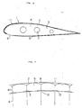
- Fig. 1 is a longitudinally sectional view of a part of the wing of a paraglider which is an embodiment of the present invention;
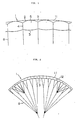
- Fig. 2 is a front view of the paraglider;
- Fig. 3 is a plan view of the paraglider;
- Fig. 4 is a side view of the paraglider;
- Fig. 5 is a perspective view of the front edge of the wing and the vicinity thereof;
- Fig. 6 is a cross-sectional view of the wing;
- Fig. 7 is a longitudinally sectional view of a part of the wing of a paraglider which is another embodiment of the present invention;
- Fig. 8 is a longitudinally sectional view of a part of the wing of a paraglider which is yet another embodiment of the present invention;
- Fig. 9 is a plan view of a part of the wing shown in Fig. 8;
- Fig. 10 is a longitudinally sectional view of a part of the wing of a conventional paraglider; and
- Fig. 11 is a cross-sectional view of the wing of the conventional paraglider.
- Embodiments of the present invention are hereinafter described in detail with reference to the drawings attached hereto.
- Figs. 1, 2, 3, 4, 5 and 6 show a paraglider which is one of the embodiments. A
wing flattener 11 nearly shaped as a band and made of a cloth of synthetic fibers is sewn to the wing 1 of the paraglider at and near the front edge of theupper side 2 of the wing along the total length thereof as follows: - (a) Some mutually sewn portions of the wing 1 and the
wing flattener 11 are the parts of theupper side 2 of the wing at the middle of the distance between the mutuallyadjacent ribs 4 of the wing and the corresponding parts of the flattener, and are shown bydotted lines 12 in Fig. 3. - (b) Other mutually sewn portions of the wing 1 and the
wing flattener 11 are the parts of the wing at the right and left ends thereof and the parts of the flattener at the right and left ends thereof. - (c) Yet other mutually sewn portions of the wing 1 and the
wing flattener 11 are the parts of theupper side 2 of the wing near the front edge of thelower side 3 thereof and the parts of the flattener at the front edge thereof. - (d) Yet other mutually sewn portions of the
wing flattener 11 and the wing 1 are the parts of the flattener at the rear edge thereof and the corresponding parts of theupper side 2 of the wing. - The operation of the paraglider which is the embodiment is described from now on. When the paraglider flies, air is taken into the
wing chambers 5 of the wing 1 throughair intake ports 6 so that the chambers are inflated and the wing is spread in an arc-shaped state as a whole. At that time, since a force acts to the wing 1 because of the flow of air thereon so as to spread the wing more, thewing flattener 11 is pulled toward the right and left ends thereof by theupper side 2 of the wing. Since thewing flattener 11 is sewn to the wing 1 at the portions (a), (b), (c) and (d) of them so that the flattener covers therecesses 9 of theupper side 2 of the wing, the flattener is stretched along the recesses because of the above-mentioned pulling or the flattener toward the right and left ends thereof by theupper side 2 so that the flattener is separated upward from the tops of theribs 4 pulled down by thesuspension lines 8 of the paraglider, and the surface of the wing is thus flattened at the place of the flattener, as shown in Fig. 1. As a result, the flow of the air on theupper side 2 of the wing 1 is smoothed to achieve the increase in the lift to the wing, the decrease in the resistance thereto, the improvement of the glide ratio of the paraglider, the decrease in the dynamic deformation of the wing and so forth to enhance the flying performance of the paraglider. - Although the
wing flattener 11 is provided only at and near the front edge of theupper side 2 of the wing 1 in the embodiment, the flattener may be provided at the other portion of the upper side or at the whole upper side. Thewing flattener 11 may also be provided at not only theupper side 2 but also thelower side 3, or at only the lower side. - Fig. 7 shows a part of a paraglider which is another of the embodiments. Wing flatteners 11 and 13 are sewn to the upper and
lower sides wing flattener 11 to theupper side 2 is the same as the preceding embodiment shown in Figs. 1, 2, 3, 4, 5 and 6. Theother wing flattener 13 is sewn to thelower side 3 as follows: - (A) Some mutually sewn portions of the
lower side 3 and thewing flattener 13 are the parts of the lower side at the middle of the distance between the mutuallyadjacent ribs 4 of the wing 1 and the corresponding parts of the flattener. - (B) Other mutually sewn portions of the
lower side 3 and thewing flattener 13 are the parts of the lower side at the right and left ends of the wing 1 and the parts of the flattener at the right and left ends thereof. - (C) Yet other mutually sewn portions of
lower side 3 and thewing flattener 13 are the parts of the lower side and near the front edge of the thereof and the parts of the flattener at the front edge thereof. - (D) Yet other mutually sewn portions of the
wing flattener 13 and thelower side 3 are the parts of the flattener at the rear edge thereof and the corresponding parts of the lower side. - Figs. 8 and 9 show a part of a paraglider which is yet another of the embodiments. In the paraglider, a
suspension line 8 is coupled to every other rib of the wing 1 of the paraglider. A plurality ofwing flatteners 14 each made of a cloth of synthetic fibers and shaped as an oblong are provided on the wing 1 so as to coverrecesses 9 made in theupper side 2 of the wing near the tops of theribs 4 of the wing. Each of thewing flatteners 14 is sewn at the right and left side edges thereof to theupper side 2 near and between theribs 4 not coupled to thesuspension lines 8, and is also sewn at the rear end of the flattener to the upper side. This embodiment produces the same effect as the preceding ones. - Although the wing flatteners are sewn to the wings in the embodiments described above, the flatteners may be attached to the wings by a different means such as adhesion.
- The surface of the wing of a paraglider provided in accordance with the present invention is flattened to smooth the flow of air on the surface to achieve the increase in the lift to the wing, the decrease in the resistance thereto, the improvement of the glide ratio of the paraglider, the decrease in the dynamic deformation of the wing and so forth to enhance the flying performance of the paraglider much more than that of the conventional paraglider. An excellent effect is thus produced.
The paraglider is the same in the other part of the constitution as the conventional paraglider shown in Figs. 10 and 11.
As a result, not only the
Claims (5)
- A paraglider comprising a wing (1) made of sheet material, which includes an upper side (2), a lower side (3), a plurality of ribs (4) provided between said sides to extend from one of said sides to the other, a plurality of wing chambers (5) defined among said sides and said ribs, and air intake ports (6) opened into said chambers at the front ends thereof; and suspension lines (8) coupled to some or all of said ribs, characterized in that said paraglider further comprises means (11,13,14) for covering recesses (9,10) which are formed in said upper side and/or said lower side and which extend in the front-to-rear direction of said wing, thereby flattening said wing.
- The paraglider according to claim 1, wherein said covering means includes a wing flattener (11,13) made of sheet material and attached to said upper side or/and said lower side so as to cover said recesses.
- The paraglider according to claim 1, wherein said covering means includes a wing flattener (11) nearly shaped as a band and made of a cloth of synthetic fibers, said wing flattener being sewn to said wing at and near the front edge of said upper side of said wing along the total length thereof.
- The paraglider according to claim 1, wherein said covering means includes wing flatteners (11,13), each of which is shaped as a band and made of a cloth of synthetic fibers, said wing flatteners being sewn to said wing at and near the front edge of said upper and lower sides of said wing along the total length thereof, respectively.
- The paraglider according to claim 1, wherein said covering means includes a plurality of wing flatteners (14), each made of a cloth of synthetic fibers and shaped as an oblong, each of said wing flatteners being attached to corresponding one of portions of said upper side and/or said lower side, where said recesses are formed, so as to cover said recesses.
Priority Applications (3)
| Application Number | Priority Date | Filing Date | Title |
|---|---|---|---|
| DE90121459T DE69002460T2 (en) | 1990-11-09 | 1990-11-09 | Paraglider. |
| EP90121459A EP0484585B1 (en) | 1990-11-09 | 1990-11-09 | Paraglider |
| AT90121459T ATE91984T1 (en) | 1990-11-09 | 1990-11-09 | PARAGLIDER. |
Applications Claiming Priority (1)
| Application Number | Priority Date | Filing Date | Title |
|---|---|---|---|
| EP90121459A EP0484585B1 (en) | 1990-11-09 | 1990-11-09 | Paraglider |
Publications (2)
| Publication Number | Publication Date |
|---|---|
| EP0484585A1 EP0484585A1 (en) | 1992-05-13 |
| EP0484585B1 true EP0484585B1 (en) | 1993-07-28 |
Family
ID=8204699
Family Applications (1)
| Application Number | Title | Priority Date | Filing Date |
|---|---|---|---|
| EP90121459A Expired - Lifetime EP0484585B1 (en) | 1990-11-09 | 1990-11-09 | Paraglider |
Country Status (3)
| Country | Link |
|---|---|
| EP (1) | EP0484585B1 (en) |
| AT (1) | ATE91984T1 (en) |
| DE (1) | DE69002460T2 (en) |
Families Citing this family (1)
| Publication number | Priority date | Publication date | Assignee | Title |
|---|---|---|---|---|
| ATE353305T1 (en) * | 2004-02-23 | 2007-02-15 | Advance Thun Ag | SLIDING OR PARACHUTE |
Family Cites Families (3)
| Publication number | Priority date | Publication date | Assignee | Title |
|---|---|---|---|---|
| US4015801A (en) * | 1974-12-02 | 1977-04-05 | Womble William H | Maneuverable, ram air inflated, flexible aerial wing |
| FR2648427A1 (en) * | 1989-06-19 | 1990-12-21 | Vermot Jacques | Device for regulation, with or without aerodynamic lift augmentation effect, for the front end of a parapent cell or a parachute inflatable by the relative wind |
| DE9015289U1 (en) * | 1990-11-07 | 1991-01-31 | Bauer, Karl, Dipl.-Ing., 8176 Schaftlach | Paragliding |
-
1990
- 1990-11-09 DE DE90121459T patent/DE69002460T2/en not_active Expired - Fee Related
- 1990-11-09 AT AT90121459T patent/ATE91984T1/en not_active IP Right Cessation
- 1990-11-09 EP EP90121459A patent/EP0484585B1/en not_active Expired - Lifetime
Also Published As
| Publication number | Publication date |
|---|---|
| ATE91984T1 (en) | 1993-08-15 |
| DE69002460D1 (en) | 1993-09-02 |
| EP0484585A1 (en) | 1992-05-13 |
| DE69002460T2 (en) | 1993-11-25 |
Similar Documents
| Publication | Publication Date | Title |
|---|---|---|
| US4406433A (en) | Leading edge inlet for ram air pressurized airfoil | |
| US4191349A (en) | Parachute having an improved multi-cell canopy | |
| US5362017A (en) | Parawing | |
| US3524613A (en) | Flexible gliding wing | |
| US3428277A (en) | Gliding parachute | |
| US3174453A (en) | Sail | |
| US3093354A (en) | Inflatable kite | |
| US4741282A (en) | Sail | |
| GB2170156A (en) | An aerial device | |
| EP0484585B1 (en) | Paraglider | |
| US5573207A (en) | Valve apparatus for ram-air wings | |
| US3480238A (en) | Glide wing | |
| US4930726A (en) | Built-in control flaps for a multi-cell wing type canopy | |
| US4658845A (en) | Umbrella cloth mounting assembly and method | |
| CA1172228A (en) | Gliding airfoil parachute canopy construction | |
| US1864964A (en) | Sail, parachute, airplane wing, and the like | |
| US2858789A (en) | Jib sail | |
| US2097475A (en) | Tape for slide fasteners | |
| US4930727A (en) | Cross braced airfoil | |
| US3366348A (en) | Aircraft high-lift wing | |
| US3612449A (en) | Boundary layer control parachutes | |
| JPH0447038Y2 (en) | ||
| US2203150A (en) | Kite | |
| JPH0316899A (en) | Paraglider | |
| GB2141079A (en) | Canopy loading system for ram air parachutes |
Legal Events
| Date | Code | Title | Description |
|---|---|---|---|
| PUAI | Public reference made under article 153(3) epc to a published international application that has entered the european phase |
Free format text: ORIGINAL CODE: 0009012 |
|
| 17P | Request for examination filed |
Effective date: 19910920 |
|
| AK | Designated contracting states |
Kind code of ref document: A1 Designated state(s): AT BE CH DE DK ES FR GB GR IT LI LU NL SE |
|
| 17Q | First examination report despatched |
Effective date: 19921111 |
|
| GRAA | (expected) grant |
Free format text: ORIGINAL CODE: 0009210 |
|
| AK | Designated contracting states |
Kind code of ref document: B1 Designated state(s): AT BE CH DE DK ES FR GB GR IT LI LU NL SE |
|
| PG25 | Lapsed in a contracting state [announced via postgrant information from national office to epo] |
Ref country code: IT Free format text: LAPSE BECAUSE OF FAILURE TO SUBMIT A TRANSLATION OF THE DESCRIPTION OR TO PAY THE FEE WITHIN THE PRE;WARNING: LAPSES OF ITALIAN PATENTS WITH EFFECTIVE DATE BEFORE 2007 MAY HAVE OCCURRED AT ANY TIME BEFORE 2007. THE CORRECT EFFECTIVE DATE MAY BE DIFFERENT FROM THE ONE RECORDED.SCRIBED TIME-LIMIT Effective date: 19930728 Ref country code: DK Effective date: 19930728 Ref country code: SE Effective date: 19930728 Ref country code: ES Free format text: THE PATENT HAS BEEN ANNULLED BY A DECISION OF A NATIONAL AUTHORITY Effective date: 19930728 Ref country code: GR Free format text: LAPSE BECAUSE OF FAILURE TO SUBMIT A TRANSLATION OF THE DESCRIPTION OR TO PAY THE FEE WITHIN THE PRESCRIBED TIME-LIMIT Effective date: 19930728 Ref country code: BE Effective date: 19930728 Ref country code: NL Effective date: 19930728 |
|
| REF | Corresponds to: |
Ref document number: 91984 Country of ref document: AT Date of ref document: 19930815 Kind code of ref document: T |
|
| REF | Corresponds to: |
Ref document number: 69002460 Country of ref document: DE Date of ref document: 19930902 |
|
| ET | Fr: translation filed | ||
| PG25 | Lapsed in a contracting state [announced via postgrant information from national office to epo] |
Ref country code: LU Free format text: LAPSE BECAUSE OF NON-PAYMENT OF DUE FEES Effective date: 19931130 |
|
| NLV1 | Nl: lapsed or annulled due to failure to fulfill the requirements of art. 29p and 29m of the patents act | ||
| PLBE | No opposition filed within time limit |
Free format text: ORIGINAL CODE: 0009261 |
|
| STAA | Information on the status of an ep patent application or granted ep patent |
Free format text: STATUS: NO OPPOSITION FILED WITHIN TIME LIMIT |
|
| 26N | No opposition filed | ||
| PGFP | Annual fee paid to national office [announced via postgrant information from national office to epo] |
Ref country code: GB Payment date: 19961031 Year of fee payment: 7 |
|
| PGFP | Annual fee paid to national office [announced via postgrant information from national office to epo] |
Ref country code: AT Payment date: 19961114 Year of fee payment: 7 Ref country code: CH Payment date: 19961114 Year of fee payment: 7 |
|
| PGFP | Annual fee paid to national office [announced via postgrant information from national office to epo] |
Ref country code: FR Payment date: 19961129 Year of fee payment: 7 |
|
| PGFP | Annual fee paid to national office [announced via postgrant information from national office to epo] |
Ref country code: DE Payment date: 19970109 Year of fee payment: 7 |
|
| PG25 | Lapsed in a contracting state [announced via postgrant information from national office to epo] |
Ref country code: GB Free format text: LAPSE BECAUSE OF NON-PAYMENT OF DUE FEES Effective date: 19971109 Ref country code: AT Free format text: LAPSE BECAUSE OF NON-PAYMENT OF DUE FEES Effective date: 19971109 |
|
| PG25 | Lapsed in a contracting state [announced via postgrant information from national office to epo] |
Ref country code: LI Free format text: LAPSE BECAUSE OF NON-PAYMENT OF DUE FEES Effective date: 19971130 Ref country code: FR Free format text: THE PATENT HAS BEEN ANNULLED BY A DECISION OF A NATIONAL AUTHORITY Effective date: 19971130 Ref country code: CH Free format text: LAPSE BECAUSE OF NON-PAYMENT OF DUE FEES Effective date: 19971130 |
|
| GBPC | Gb: european patent ceased through non-payment of renewal fee |
Effective date: 19971109 |
|
| REG | Reference to a national code |
Ref country code: CH Ref legal event code: PL |
|
| PG25 | Lapsed in a contracting state [announced via postgrant information from national office to epo] |
Ref country code: DE Free format text: LAPSE BECAUSE OF NON-PAYMENT OF DUE FEES Effective date: 19980801 |
|
| REG | Reference to a national code |
Ref country code: FR Ref legal event code: ST |