EP0484531A1 - Reinforcing element for dispersed reinforcement of concrete - Google Patents
Reinforcing element for dispersed reinforcement of concrete Download PDFInfo
- Publication number
- EP0484531A1 EP0484531A1 EP90912886A EP90912886A EP0484531A1 EP 0484531 A1 EP0484531 A1 EP 0484531A1 EP 90912886 A EP90912886 A EP 90912886A EP 90912886 A EP90912886 A EP 90912886A EP 0484531 A1 EP0484531 A1 EP 0484531A1
- Authority
- EP
- European Patent Office
- Prior art keywords
- sections
- concrete
- reinforcing element
- parts
- section
- Prior art date
- Legal status (The legal status is an assumption and is not a legal conclusion. Google has not performed a legal analysis and makes no representation as to the accuracy of the status listed.)
- Withdrawn
Links
Images

Classifications
-
- E—FIXED CONSTRUCTIONS
- E04—BUILDING
- E04C—STRUCTURAL ELEMENTS; BUILDING MATERIALS
- E04C5/00—Reinforcing elements, e.g. for concrete; Auxiliary elements therefor
- E04C5/01—Reinforcing elements of metal, e.g. with non-structural coatings
- E04C5/012—Discrete reinforcing elements, e.g. fibres
Definitions
- the present invention relates to construction materials or, more particularly, to reinforcing elements used for dispersion reinforcement of concrete.
- Reinforcing elements used in dispersion reinforcement of concrete and comprised in the reinforced concrete composition are uniformly distributed through its volume during manufacture. Should any cracks occur within the reinforced concrete, the reinforcing elements will prevent them from developing any further, taking up the stresses transmitted frog the concrete. Structures fabricated from reinforced concrete are generally subject to alternating loads. It is this factor that determines the basic requirements that the reinforcing elements are supposed to meet, viz.: high element strength and high reliability of the element retention in a concrete.
- High reinforcing element strength can be achieved by eliminating from the reinforcing element such high stress concentrators that may lead to breakdown of the element.
- High reliability of the element retention in a concrete can be attained by increasing the mechanical bonding between the element and the concrete due to irregularities provided on the element surface, as well as by improving the engagement of the element within the concrete owing to the presence of anchorage zones in the element.
- a reinforcing element for dispersion reinforcement of concrete (FR, B, 2061681), having the form of a wire length with bent ends.
- the bent ends make anchorage zones providing mechanical engagement for the reinforcing element.
- the wire bend points bake stress concentrators, whose presence in the element will lower its strength.
- the stresses transmitted from the concrete are chiefly applied to the relatively small sections of the element, i.e. to its bent ends, leading to considerably increased stresses therein and thereby to still lower element strength.
- Another disadvantage inherent in these elements is their tendency to aggregate - due to the presence of bent ends. The result is the necessity for undertaking arduous operations to separate elements from one another, as well as reduced uniformity of their distribution in the concrete. Said disadvantages combine to reduce the strength of reinforced concrete structures.
- Another known reinforcing element for dispersion reinforcement of concrete (SU, A, 1353876) consists of an elongated metal body C-shaped in cross section and comprising anchorage zones. These zones are formed as bulges provided on the concave side of the elongated metal body at one of its ends.
- One of the surfaces of the reinforcing element is made rough, thus providing an increased bond surface between element and concrete.
- the bulges forming the anchrorage zones serve as relatively high stress concentrators, leading to lower reinforcing element strength.
- making only one of the element surfaces leads to unequal bond strengths between these surfaces and the concrete. This initiates additional bending stresses in the element, this also reducing the strength of the reinforcing element and thereby decreasing the reliability of reinforced concrete structures.
- the present invention is based upon the objective of providing a reinforcing element for dispersion reinforcement of concrete, wherein the anchorage zones would be executed so as to enhance the strength of the element while providing for its reliable retention within the concrete thus improving the reliability of the reinforced concrete structure.
- a reinforcing element for dispersion reinforcement of concrete comprising an elongated metal body C-shaped in cross section and containing anchorage zones, in which element said body comprises, in accordance with the invention, interconjugated convex and concave sections as viewed in the longitudinal section, said convex and concave sections forming anchorage zones.
- the reinforcing element may have different embodiments. In some of these embodiments, the reinforcing element contains intermediate sections interconnecting adjacent concave sections. In other embodiments there are none of such intermediate sections.
- the reinforcing element is such that there are two concave sections interconnected by an intermediate section conjugated with these concave sections between each two adjacent convex sections
- said intermediate section to consist of two parts, each being of rectilinear form in the longitudinal section and executed and arranged relative to each other in a manner such that in the longitudinal section of the elongated metal body the ratio of the distance between the two points, farthest removed from each other,on each two adjacent convex sections to the sum of the lengths of these two adjacent sections would be between 2.0 and 2.5
- said parts of said intermediate section would be disposed at an angle to the longitudinal axis of the metal body and at an angle relative to each other, and the spot on each of the two parts of the intermediate section, farthest removed from the nominal straight line passing through the vertices of said convex sections, would be the point of intersection of these two parts.
- This embodiment of the reinforcing element permits of easy fabrication while retaining high element strength and reliable element retention in concrete.
- the reinforcing element for dispersion reinforcement of concrete is made in the form of an elongated metal body 1 C-shaped in cross section.
- the body 1 In the longitudinal section (FIG.2), the body 1 has convex sections 2 and concave sections 3 conjugated with one another.
- the longitudinally convex and concave sections 2 and 3 form anchorage zones in the body 1.
- Adjacent concave sections 3 are interconnected by means of an intermediate section 4 conjugated with these concave sections 3.
- the intermediate section 4 consists of two parts 4a and 4b, each of the latter being longitudinally of rectilinear form.
- the ratio of the distance C between two points, farthest removed from each other, on each two adjacent convex sections 2 to the sum of the lengths d1 and d2 of these two adjacent sections 2 is within 2.0 to 2.5.
- the parts 4a and 4b are disposed at an angle ⁇ to the longitudinal axis 5 of the body 1 and at an angle ⁇ to each other.
- the spot on each of the two parts 4a and 4b of the intermediate section 4, farthest removed from a nominal straight line 6 passing through the vertices of said convex sections 2, is the intersection 7 of said parts 4a and 4b.
- the angles ⁇ and ⁇ may be different in different longitudinal sections of the element and vary from the angles ⁇ and ⁇ in the longitudinal section as illustrated in FIG.2.
- angle ⁇ is selected based on the provision of reliable retention of the reinforcing element in concrete.
- the value of angle ⁇ can be determined in a known manner for various reinforcing elements and various concrete compositions. The inventors have established both by calculation and experimentally that at angles ⁇ les than 1.5 o the reliability of element retention in concrete is considerably lowered. In practice, elements have been produced with a maximum angle equal to 5 o .
- the reinforcing element without an intermediate section 4 is possible, as shown in FIG.3.
- the element has the form of a body 9 having in the longitudinal section only convex and concave sections 10 and 11, respectively, in alternate arrangement.
- a reinforcing element is less easy to fabricate.
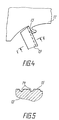
- Fabrication of a reinforcing element is carried out in a known manner by machining a steel blank (casting or slab) 12 (FIG.4) using a milling tool (not shown) fitted with grooves 14 (FIG.5) in the front surface 15 of the cutting blade 13.
- the convex sections 2 (FIG.2), concave sections 3, and intermediate section 4 of the body 1 are formed directly in the process of fabrication of the reinforcing element as a result of deformation of the cut-away metal (chips) in the cutting zone which are in the state of plastic flow, filling the grooves 14 (FIG.5).
- the convex and concave sections 10 and 11, respectively, of the body 9 are formed in a similar way directly in the process of fabrication.
- the grooves 14 (FIG.5) provided in the milling tool are arranged close to one another while the cutting blade edge sections in between said grooves 14 are small in length. It has been established experimentally that in the cutting process the main load is that affecting these edge sections. High stress concentrations at these sections, resulting from their small lengths, will lead to considerable chipping in these sections and therefore to high wear on the cutting blade of the milling tool.
- FIGS.1 and 2 To fabricate the element shown in FIGS.1 and 2, use is made of a milling tool, in which the grooves 14 (FIG.5) are arranged at a large distance from one another. Increasing the length of the cutting blade sections in between the grooves 14 will reduce the specific loads on these sections, resulting in lower wear on the cutting blade and therefore making element fabrication less difficult.
- the ratio of the distance C to the sum of the lengths d1 and d2 of the convex sections 2 is less than 2.0, the ease of fabrication of the element is reduced due to the wear on the cutting blade of the milling tool, caused by the small lengths of the edge sections in between the grooves.
- the reinforcing element illustrated in FIG.3 does not comprise any relatively high stress concentrators either, which makes for higher strength.
- the stresses transmitted from the concrete are distributed over the entire length of the element, which also increases its strength.
- anchorage zones occupy the entire length of the body 9, assuring good engagement for the element in concrete and thus its adequate retention in concrete. All this combines to enhance the reliability of the reinforced concrete structure using a concrete reinforced with such reinforcing elements.
- the proposed reinforcing element can be used in the fabrication of building structures and products based on the use of composite material, thus a concrete mix reinforced with steel fibers.
Landscapes
- Engineering & Computer Science (AREA)
- Architecture (AREA)
- Civil Engineering (AREA)
- Structural Engineering (AREA)
- Nitrogen And Oxygen Or Sulfur-Condensed Heterocyclic Ring Systems (AREA)
- Reinforcement Elements For Buildings (AREA)
Abstract
A reinforcing element consists of an elongated metal body (1) "U" shaped in its cross-section and provided, in its longitudinal cross-section, with convex (2), concave (3) and intermediate sections (4) interconjugating and constituting anchor sections. The intermediate section (4) consists of two parts (4a) and (4b) oriented at an angle α to the longitudinal axis (5) of the body (1) and at an angle β to each other.
Description
- The present invention relates to construction materials or, more particularly, to reinforcing elements used for dispersion reinforcement of concrete.
- Reinforcing elements used in dispersion reinforcement of concrete and comprised in the reinforced concrete composition are uniformly distributed through its volume during manufacture. Should any cracks occur within the reinforced concrete, the reinforcing elements will prevent them from developing any further, taking up the stresses transmitted frog the concrete. Structures fabricated from reinforced concrete are generally subject to alternating loads. It is this factor that determines the basic requirements that the reinforcing elements are supposed to meet, viz.: high element strength and high reliability of the element retention in a concrete.
- High reinforcing element strength can be achieved by eliminating from the reinforcing element such high stress concentrators that may lead to breakdown of the element.
- High reliability of the element retention in a concrete can be attained by increasing the mechanical bonding between the element and the concrete due to irregularities provided on the element surface, as well as by improving the engagement of the element within the concrete owing to the presence of anchorage zones in the element.
- Realization of these basic requirements for reinforcing elements will lead to higher reliability in reinforced concrete structures.
- There is known a reinforcing element for dispersion reinforcement of concrete (FR, B, 2061681), having the form of a wire length with bent ends. The bent ends make anchorage zones providing mechanical engagement for the reinforcing element. The wire bend points bake stress concentrators, whose presence in the element will lower its strength. Besides, the stresses transmitted from the concrete are chiefly applied to the relatively small sections of the element, i.e. to its bent ends, leading to considerably increased stresses therein and thereby to still lower element strength. Another disadvantage inherent in these elements is their tendency to aggregate - due to the presence of bent ends. The result is the necessity for undertaking arduous operations to separate elements from one another, as well as reduced uniformity of their distribution in the concrete. Said disadvantages combine to reduce the strength of reinforced concrete structures.
- Another known reinforcing element for dispersion reinforcement of concrete (SU, A, 1353876) consists of an elongated metal body C-shaped in cross section and comprising anchorage zones. These zones are formed as bulges provided on the concave side of the elongated metal body at one of its ends. One of the surfaces of the reinforcing element is made rough, thus providing an increased bond surface between element and concrete. However the bulges forming the anchrorage zones serve as relatively high stress concentrators, leading to lower reinforcing element strength. Besides, making only one of the element surfaces leads to unequal bond strengths between these surfaces and the concrete. This initiates additional bending stresses in the element, this also reducing the strength of the reinforcing element and thereby decreasing the reliability of reinforced concrete structures.
- The present invention is based upon the objective of providing a reinforcing element for dispersion reinforcement of concrete, wherein the anchorage zones would be executed so as to enhance the strength of the element while providing for its reliable retention within the concrete thus improving the reliability of the reinforced concrete structure.
- The objective as stated above is achieved by providing a reinforcing element for dispersion reinforcement of concrete, comprising an elongated metal body C-shaped in cross section and containing anchorage zones, in which element said body comprises, in accordance with the invention, interconjugated convex and concave sections as viewed in the longitudinal section, said convex and concave sections forming anchorage zones.
- Providing anchorage zones in the form of interconjugated convex and concave body sections as viewed in the longitudinal section avoids the presence of relatively high stress concentrators owing to gradual conjugation of the sections. This makes for increased reinforcing element strength. Besides, the stresses transmitted from the concrete are distributed along the entire length of the convex and concave body sections, which also serves to increase the strength of the element. Also, this arrangement provides for reliable retention of the element in the concrete, due to the engagement therein of the convex and concave sections of the body.
- The reinforcing element may have different embodiments. In some of these embodiments, the reinforcing element contains intermediate sections interconnecting adjacent concave sections. In other embodiments there are none of such intermediate sections.
- Where the reinforcing element is such that there are two concave sections interconnected by an intermediate section conjugated with these concave sections between each two adjacent convex sections, it is convenient for said intermediate section to consist of two parts, each being of rectilinear form in the longitudinal section and executed and arranged relative to each other in a manner such that in the longitudinal section of the elongated metal body the ratio of the distance between the two points, farthest removed from each other,on each two adjacent convex sections to the sum of the lengths of these two adjacent sections would be between 2.0 and 2.5, said parts of said intermediate section would be disposed at an angle to the longitudinal axis of the metal body and at an angle relative to each other, and the spot on each of the two parts of the intermediate section, farthest removed from the nominal straight line passing through the vertices of said convex sections, would be the point of intersection of these two parts.
- This embodiment of the reinforcing element permits of easy fabrication while retaining high element strength and reliable element retention in concrete.
- The invention will be more fully apparent through a detailed description of its embodiments taken in conjunction with the accompanying drawings, wherein:
- FIG.1
- illustrates, in axonometric projection, a portion of the reinforcing element for dispersion reinforcement of concrete, fabricated in accordance with the invention;
- FIG.2
- illustrates a portion of the longitudinal section of the reinforcing element;
- FIG.3
- illustrates a portion of the longitudinal section of the reinforcing element fabricated in accordance with another embodiment of the invention;
- FIG.4
- is a schematic illustration of the mutual arrangement of a blank and the cutting blade of a milling tool in the process of fabrication of a reinforcing element; and
- FIG.5
- is a sectional view taken along the line V-V of FIG.4.
- In accordance with FIG.1, the reinforcing element for dispersion reinforcement of concrete is made in the form of an elongated metal body 1 C-shaped in cross section. In the longitudinal section (FIG.2), the body 1 has convex
sections 2 andconcave sections 3 conjugated with one another. The longitudinally convex andconcave sections concave sections 3 are interconnected by means of anintermediate section 4 conjugated with theseconcave sections 3. Theintermediate section 4 consists of two parts 4a and 4b, each of the latter being longitudinally of rectilinear form. The ratio of the distance C between two points, farthest removed from each other, on each twoadjacent convex sections 2 to the sum of the lengths d₁ and d₂ of these twoadjacent sections 2 is within 2.0 to 2.5. The parts 4a and 4b are disposed at an angle α to the longitudinal axis 5 of the body 1 and at an angle β to each other. The spot on each of the two parts 4a and 4b of theintermediate section 4, farthest removed from a nominal straight line 6 passing through the vertices of saidconvex sections 2, is theintersection 7 of said parts 4a and 4b. The angles α and β may be different in different longitudinal sections of the element and vary from the angles α and β in the longitudinal section as illustrated in FIG.2. The angle α is selected based on the provision of reliable retention of the reinforcing element in concrete. The value of angle α can be determined in a known manner for various reinforcing elements and various concrete compositions. The inventors have established both by calculation and experimentally that at angles α les than 1.5o the reliability of element retention in concrete is considerably lowered. In practice, elements have been produced with a maximum angle equal to 5o. - An embodiment of the reinforcing element without an
intermediate section 4 is possible, as shown in FIG.3. In this embodiment, the element has the form of a body 9 having in the longitudinal section only convex andconcave sections - Fabrication of a reinforcing element is carried out in a known manner by machining a steel blank (casting or slab) 12 (FIG.4) using a milling tool (not shown) fitted with grooves 14 (FIG.5) in the
front surface 15 of thecutting blade 13. The convex sections 2 (FIG.2),concave sections 3, andintermediate section 4 of the body 1 are formed directly in the process of fabrication of the reinforcing element as a result of deformation of the cut-away metal (chips) in the cutting zone which are in the state of plastic flow, filling the grooves 14 (FIG.5). - In the case of fabrication of the reinforcing element illustrated in FIG.3, the convex and
concave sections grooves 14 are small in length. It has been established experimentally that in the cutting process the main load is that affecting these edge sections. High stress concentrations at these sections, resulting from their small lengths, will lead to considerable chipping in these sections and therefore to high wear on the cutting blade of the milling tool. To fabricate the element shown in FIGS.1 and 2, use is made of a milling tool, in which the grooves 14 (FIG.5) are arranged at a large distance from one another. Increasing the length of the cutting blade sections in between thegrooves 14 will reduce the specific loads on these sections, resulting in lower wear on the cutting blade and therefore making element fabrication less difficult. - Owing to the parts 4a and 4b (FIG.2) of the
intermediate section 4 being disposed at an angle α to the longitudinal axis 5 of the body 1, good engagement is assured for the element in concrete, and thereby its reliable retention in concrete. Thanks to the smooth interconnection of thesections - If the ratio of the distance C to the sum of the lengths d₁ and d₂ of the
convex sections 2 is less than 2.0, the ease of fabrication of the element is reduced due to the wear on the cutting blade of the milling tool, caused by the small lengths of the edge sections in between the grooves. - If this ratio is more than 2.5, then, as shown experimentally, there is formed between the parts 4a and 4b a part oriented along the longitudinal axis 5 of the body 1. The presence of such a part - which does not serve as an anchorage zone - impaire the element engagement within the concrete and by virtue of this reduces the reliability of its retention in the concrete.
- The reinforcing element illustrated in FIG.3 does not comprise any relatively high stress concentrators either, which makes for higher strength. In a leaded reinforced concrete structure, the stresses transmitted from the concrete are distributed over the entire length of the element, which also increases its strength. Owing to the alternation of convex and
concave sections - The proposed reinforcing element can be used in the fabrication of building structures and products based on the use of composite material, thus a concrete mix reinforced with steel fibers.
Claims (2)
- A reinforcing element for dispersion reinforcement of concrete, comprising an elongated metal body (1) C-shaped in cross section and containing anchorage zones, characterized in that said body (1) has interconjugated convex sections (2) and concave sections (3) as viewed in the longitudinal section, said convex sections (2) and concave sections (3) forming anchorage zones.
- A reinforcing element for dispersion reinforcement of concrete as defined in Claim 1, wherein between each two adjacent convex sections (2) there are two concave sections (3) interconnected by an intermediate section (4) conjugated with said concave sections (3), characterized in that said intermediate section (4) consists of two parts (4a) and (4b) having each rectilinear form longitudinally, fabricated and arranged relative to each other in a manner such that in the longitudinal section of the elongated metal body (1) the ratio of the distance (C) between two points, farthest removed from each other, on each two adjacent convex sections (2) to the sum of the lengths (d₁) and (d₂) of these two adjacent sections (2) is within 2.0 to 2.5, said parts (4a) and (4b) of the intermediate section (4) are disposed at an angle ( α ) to the longitudinal axis (5) of said body (1) and at an angle ( β ) relative to each other, and the spot on each of the two parts (4a) and (4b) of the intermediate section (4), farthest removed from the nominal straight line passing through the vertices of said convex sections (2), is the intersection (7) of said two parts (4a) and (4b).
Applications Claiming Priority (2)
| Application Number | Priority Date | Filing Date | Title |
|---|---|---|---|
| SU4733667 | 1989-07-26 | ||
| SU894733667A SU1679008A1 (en) | 1989-07-26 | 1989-07-26 | Reinforcement member for continuously reinforcing concrete |
Publications (2)
| Publication Number | Publication Date |
|---|---|
| EP0484531A1 true EP0484531A1 (en) | 1992-05-13 |
| EP0484531A4 EP0484531A4 (en) | 1992-12-02 |
Family
ID=21467980
Family Applications (1)
| Application Number | Title | Priority Date | Filing Date |
|---|---|---|---|
| EP19900912886 Withdrawn EP0484531A4 (en) | 1989-07-26 | 1990-07-05 | Reinforcing element for dispersed reinforcement of concrete |
Country Status (4)
| Country | Link |
|---|---|
| EP (1) | EP0484531A4 (en) |
| FI (1) | FI920320A0 (en) |
| SU (1) | SU1679008A1 (en) |
| WO (1) | WO1991002130A1 (en) |
Cited By (1)
| Publication number | Priority date | Publication date | Assignee | Title |
|---|---|---|---|---|
| US20170283320A1 (en) * | 2014-09-24 | 2017-10-05 | Kosteel Co., Ltd. | Arched steel fibers for reinforcing cement-based material |
Families Citing this family (2)
| Publication number | Priority date | Publication date | Assignee | Title |
|---|---|---|---|---|
| FR2740335B1 (en) * | 1995-10-26 | 1997-12-19 | Oreal | USE OF LANTHANIDE, LITHIUM, TIN, ZINC, MANGANESE OR YTTRIUM SALT AS A SUBSTANCE P ANTAGONIST |
| CN107932004B (en) * | 2017-12-20 | 2019-08-30 | 河北纵横集团丰南钢铁有限公司 | A kind of manufacturing method of part boss steel plate strip |
Family Cites Families (7)
| Publication number | Priority date | Publication date | Assignee | Title |
|---|---|---|---|---|
| FR2393896A1 (en) * | 1977-06-06 | 1979-01-05 | Michelin & Cie | CORRUGATED METAL WIRE FOR ARMING COMPOSITE MATERIALS |
| DE2832495C2 (en) * | 1978-07-25 | 1984-07-12 | Van Thiel's Draadindustrie (Thibodraad) B.V., Beek en Donk | Reinforcement fiber and device for the production of the reinforcement fiber |
| ATE25727T1 (en) * | 1982-07-01 | 1987-03-15 | Eurosteel Sa | REINFORCEMENT FIBERS FOR PASTABLE BUILDING MATERIALS WITH HYDRAULIC OR OTHER BINDERS AND THEIR PRODUCTION. |
| SU1213156A1 (en) * | 1984-08-31 | 1986-02-23 | Комбинат "Стройиндустрия" Главмоспромстройматериалов | Reinforcement element for dispersed reinforcement of concrete |
| SU1213157A1 (en) * | 1984-09-07 | 1986-02-23 | Челябинский Политехнический Институт Им.Ленинского Комсомола | Reinforcement element for dispersed reinforcement of concrete and apparatus for manufacturing same |
| SU1384688A1 (en) * | 1986-10-08 | 1988-03-30 | Ленинградский зональный научно-исследовательский и проектный институт типового и экспериментального проектирования жилых и общественных зданий | Reinforcement element for particulate reinforcement of concrete |
| SU1479590A1 (en) * | 1987-09-24 | 1989-05-15 | Волховский Комбинат Строительных Конструкций | Reinforcement member for dispersed reinforcing, and apparatus for making same |
-
1989
- 1989-07-26 SU SU894733667A patent/SU1679008A1/en active
-
1990
- 1990-07-05 EP EP19900912886 patent/EP0484531A4/en not_active Withdrawn
- 1990-07-05 WO PCT/SU1990/000174 patent/WO1991002130A1/en not_active Application Discontinuation
-
1992
- 1992-01-24 FI FI920320A patent/FI920320A0/en not_active Application Discontinuation
Non-Patent Citations (2)
| Title |
|---|
| No further relevant documents disclosed * |
| See also references of WO9102130A1 * |
Cited By (2)
| Publication number | Priority date | Publication date | Assignee | Title |
|---|---|---|---|---|
| US20170283320A1 (en) * | 2014-09-24 | 2017-10-05 | Kosteel Co., Ltd. | Arched steel fibers for reinforcing cement-based material |
| US10414691B2 (en) * | 2014-09-24 | 2019-09-17 | Kosteel Co., Ltd. | Arched steel fibers for reinforcing cement-based material |
Also Published As
| Publication number | Publication date |
|---|---|
| EP0484531A4 (en) | 1992-12-02 |
| WO1991002130A1 (en) | 1991-02-21 |
| SU1679008A1 (en) | 1991-09-23 |
| FI920320A0 (en) | 1992-01-24 |
Similar Documents
| Publication | Publication Date | Title |
|---|---|---|
| US3183628A (en) | Masonry wall reinforcing means | |
| EP2652221B1 (en) | Steel fibre reinforced concrete | |
| US9435122B2 (en) | Steel fibre for reinforcing concrete or mortar having an anchorage end with at least three straight sections | |
| US5865000A (en) | Steel fiber reinforced concrete with high flexural strength | |
| US5651635A (en) | Concrete barrier with reinforcement | |
| SK284180B6 (en) | Steel wire element for mixing into subsequently hardening materials | |
| SU1036252A3 (en) | Reinforcement member for disperse reinforcement of concrete | |
| EP0484531A1 (en) | Reinforcing element for dispersed reinforcement of concrete | |
| JP4412196B2 (en) | Calculation method of shear strength of reinforced concrete beam, design method using this calculation method, reinforced concrete beam designed by this design method and beam / floor structure of reinforced concrete | |
| KR200406191Y1 (en) | Steel fiber for Reinforcing concrete | |
| JPH05156720A (en) | Welding connector | |
| KR20180008206A (en) | Concrete Precast Slab | |
| GB2149832A (en) | Stirrup basket | |
| DE19835075A1 (en) | Reinforcing fibers for hardenable materials, especially concrete, comprises twisted instead of notched fibers to enhance grip with the matrix material | |
| JPH06294017A (en) | Steel fiber for concrete reinforcement | |
| HU185499B (en) | Lattise truss | |
| EP2652220B1 (en) | Steel fibre for reinforcing concrete or mortar provided with flattened sections | |
| US3323263A (en) | Long-span prestressed beam structure | |
| US3335539A (en) | Spirally ribbed reinforcing bar for concrete | |
| US542206A (en) | Concrete-iron construction | |
| JPH0531620B2 (en) | ||
| SU1127960A1 (en) | Reinforced concrete beam | |
| EP0351229A2 (en) | Improvements relating to soil reinforcement | |
| CN220377655U (en) | Transverse steel bar for reinforced concrete member | |
| JPS6113612Y2 (en) |
Legal Events
| Date | Code | Title | Description |
|---|---|---|---|
| PUAI | Public reference made under article 153(3) epc to a published international application that has entered the european phase |
Free format text: ORIGINAL CODE: 0009012 |
|
| 17P | Request for examination filed |
Effective date: 19920213 |
|
| AK | Designated contracting states |
Kind code of ref document: A1 Designated state(s): AT BE DE FR |
|
| A4 | Supplementary search report drawn up and despatched |
Effective date: 19921009 |
|
| AK | Designated contracting states |
Kind code of ref document: A4 Designated state(s): AT BE DE FR |
|
| 17Q | First examination report despatched |
Effective date: 19930712 |
|
| STAA | Information on the status of an ep patent application or granted ep patent |
Free format text: STATUS: THE APPLICATION IS DEEMED TO BE WITHDRAWN |
|
| 18D | Application deemed to be withdrawn |
Effective date: 19931123 |