EP0484345B1 - Improvements in and relating to composite beams - Google Patents
Improvements in and relating to composite beams Download PDFInfo
- Publication number
- EP0484345B1 EP0484345B1 EP90909826A EP90909826A EP0484345B1 EP 0484345 B1 EP0484345 B1 EP 0484345B1 EP 90909826 A EP90909826 A EP 90909826A EP 90909826 A EP90909826 A EP 90909826A EP 0484345 B1 EP0484345 B1 EP 0484345B1
- Authority
- EP
- European Patent Office
- Prior art keywords
- ladder
- profiles
- concrete
- steel
- connecting elements
- Prior art date
- Legal status (The legal status is an assumption and is not a legal conclusion. Google has not performed a legal analysis and makes no representation as to the accuracy of the status listed.)
- Expired - Lifetime
Links
Images
Classifications
-
- E—FIXED CONSTRUCTIONS
- E04—BUILDING
- E04C—STRUCTURAL ELEMENTS; BUILDING MATERIALS
- E04C3/00—Structural elongated elements designed for load-supporting
- E04C3/02—Joists; Girders, trusses, or trusslike structures, e.g. prefabricated; Lintels; Transoms; Braces
- E04C3/29—Joists; Girders, trusses, or trusslike structures, e.g. prefabricated; Lintels; Transoms; Braces built-up from parts of different material, i.e. composite structures
- E04C3/293—Joists; Girders, trusses, or trusslike structures, e.g. prefabricated; Lintels; Transoms; Braces built-up from parts of different material, i.e. composite structures the materials being steel and concrete
-
- E—FIXED CONSTRUCTIONS
- E04—BUILDING
- E04B—GENERAL BUILDING CONSTRUCTIONS; WALLS, e.g. PARTITIONS; ROOFS; FLOORS; CEILINGS; INSULATION OR OTHER PROTECTION OF BUILDINGS
- E04B5/00—Floors; Floor construction with regard to insulation; Connections specially adapted therefor
- E04B5/16—Load-carrying floor structures wholly or partly cast or similarly formed in situ
- E04B5/17—Floor structures partly formed in situ
- E04B5/23—Floor structures partly formed in situ with stiffening ribs or other beam-like formations wholly or partly prefabricated
- E04B5/29—Floor structures partly formed in situ with stiffening ribs or other beam-like formations wholly or partly prefabricated the prefabricated parts of the beams consisting wholly of metal
-
- E—FIXED CONSTRUCTIONS
- E04—BUILDING
- E04C—STRUCTURAL ELEMENTS; BUILDING MATERIALS
- E04C5/00—Reinforcing elements, e.g. for concrete; Auxiliary elements therefor
- E04C5/01—Reinforcing elements of metal, e.g. with non-structural coatings
- E04C5/06—Reinforcing elements of metal, e.g. with non-structural coatings of high bending resistance, i.e. of essentially three-dimensional extent, e.g. lattice girders
Landscapes
- Engineering & Computer Science (AREA)
- Architecture (AREA)
- Civil Engineering (AREA)
- Structural Engineering (AREA)
- Chemical & Material Sciences (AREA)
- Composite Materials (AREA)
- Physics & Mathematics (AREA)
- Electromagnetism (AREA)
- Rod-Shaped Construction Members (AREA)
- Joining Of Building Structures In Genera (AREA)
- Ladders (AREA)
- Reinforcement Elements For Buildings (AREA)
Abstract
Description
- The present invention relates to an improvement in a twin-webbed floor beam of steel in composite action with concrete, wherein said beam comprises at least one projecting, horizontal bearing plate for supporting floor structures and said improvement consists of a ladder intended to be fastened to an upper part of the beam in its longitudinal extension.
- For steel beams in composite action with concrete it is necessary that the transmission of shear force between the steel cross-section and concrete is guaranteed. This is often done by aid of so called studs (bolts), which are welded to the steel beam, preferably to its upper flange. Depending on actual forces which shall be transmitted, a lot of studs can be required. In the composite cross-section concrete only takes up compression forces, sometimes together with a smaller part of the steel cross-section, while the tensile forces are only taken up by the steel. Before the concrete has hardened the load carrying capacity is therefore limited since the concrete compression zone is lacking. The load carrying capacity of the steel cross-section itself often is so limited that not even the dead load of the floor can be supported, hence the beam must be propped until the concrete has obtained the strength required. The propping involves an evident drawback, since it often is a bar for rational construction.
- US-A-2 731 824 discloses a steel beam comprising a projecting horizontal bearing plate suitable for supporting floor structures and a ladder which is fastened to an upper part of the beam, and which comprises two longitudinal profiles running parallel to and in a predetermined distance from each other and a number of transverse connecting elements extending between said profiles in a predetermined distance from each other. However, here the function is not a static composite action construction between steel and concrete as the fact is according to the present invention, but the concrete takes mainly the the forces and the function of the steel envelope or housing is to facilitate cross-connecting between the arces. The ties which have a ladderlike appearance have no force transfering function, but only a function in keeping together the two parts of the steel envelope.
- An object of the present invention is to provide an improvement in the form of a separate and prefabricated ladder in composite beams by which the steel area of the upper part of a beam in a simple way can be increased and hereby increase the compression zone of the steel cross-section before the hardening of the concrete. By this the need for propping is eliminated in the same time as said ladder in an effective way guarantee the transmission of shear force between steel and concrete in the composite cross-section. The ladder also means that the manufacturing of the same can be rationalized in that it can be prefabricated in a number of variants and sizes and be kept in stock for use to different beam sizes depending on loads and spans. The ladder also has such a design that it very easy and quickly can be fixed to the upper part of a floor structure supporting beam e.g by longutudinal, intermittent welding, which also can be performed by an automatic machine. The characteristic features of the invention are set forth in the following claims.
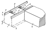
- The invention will now be described in more detail below with reference to the accompanying drawing, which illustrates a preferable embodiment of the ladder according to the invention in a schematic perspective view, when it is mounted to the upper part of a steel beam schematically indicated.
- As will be seen from the drawing it illustrates a schematically indicated, as a composite beam formed steel twin-webbed beam 1 in a perspective view having a preferable embodiment of the present invention in the form of a
prefabricated ladder 2, which is fastened to an upper part 6 of the beam 1 in its longitudinal extension. The beam 1 is made of steel and has a form not closer illustrated in the drawing, which admits a composite action with concrete and comprises at least one projecting, horizontal bearing plate 3 for supportingfloor structures 4. Theprefabricated ladder 2 comprises at least twolongitudinal profiles 5 running parallel to and at a predetermined distance from each other, saidprofiles 5 are positionally fixable to the upper part 6 of the beam 1. In the preferred embodiment illustrated, theprofiles 5 consist of steel bars of rectangular cross section. A number of transverse connecting elements 7 provided in a predetermined distance from each other extend between theprofiles 5. These bring about necessary transmission of shear force for static composite action between the beam 1 and concrete which is performed later. - In a preferred embodiment according to the present invention, the connecting elements 7 consist of steel angle profiles with an
apex formation 8, which are fixed by welding to thelongitudinal profiles 5 with their axes perpendicular to the webs of said twin-webbed beam. The connecting elements 7 can be designed with any suitable form, but steel angle profiles are to be preferred. The connecting elements 7 are mounted parallel to each other with a mutual spacing of about 200-600 mm along the whole extension of theladder 2.
Claims (4)
- A ladder in a steel twin-webbed beam (1) for use in composite action with concrete, said beam (1) comprising at least a projecting, horizontal bearing plate (3) for supporting floor structures (4) and said ladder (2) being fastenable to an upper part (6) of said twin-webbed beam (1), characterized in that said ladder (2) is a separate and prefabricated ladder comprising at least two longitudinal profiles (5) running parallel to and at a predetermined distance from each other, said profiles (5) are positionally fixable to the upper part (6) of the beam (1) and between said profiles a number of transverse shear connecting elements (7) extend at a pre-determined spacing from each other for transfer of shear force between the beam (1) and concrete under said composite action.
- A ladder according to claim 1, characterized in that the connecting elements (7) consist of steel angle profiles, which are fixed to the longitudinal profiles (5) with their axes perpendicular to the webs of said twin-webbed beam.
- A ladder according to claim 1, characterized in that the longitudinal profiles (5) consist of steel bars of rectangular cross section.
- A ladder according to claim 1 or 2, characterized in that the connecting elements (7) are provided parallel to each other with a mutual spacing of about 200-600 mm.
Applications Claiming Priority (3)
| Application Number | Priority Date | Filing Date | Title |
|---|---|---|---|
| SE8902163 | 1989-06-15 | ||
| SE8902163A SE466609B (en) | 1989-06-15 | 1989-06-15 | DEVICE AT A COLLABORATION BALL |
| PCT/SE1990/000427 WO1990015907A1 (en) | 1989-06-15 | 1990-06-15 | Improvements in and relating to composite beams |
Publications (2)
| Publication Number | Publication Date |
|---|---|
| EP0484345A1 EP0484345A1 (en) | 1992-05-13 |
| EP0484345B1 true EP0484345B1 (en) | 1994-12-21 |
Family
ID=20376291
Family Applications (1)
| Application Number | Title | Priority Date | Filing Date |
|---|---|---|---|
| EP90909826A Expired - Lifetime EP0484345B1 (en) | 1989-06-15 | 1990-06-15 | Improvements in and relating to composite beams |
Country Status (5)
| Country | Link |
|---|---|
| EP (1) | EP0484345B1 (en) |
| AU (1) | AU5846090A (en) |
| DE (1) | DE69015360T2 (en) |
| SE (1) | SE466609B (en) |
| WO (1) | WO1990015907A1 (en) |
Family Cites Families (5)
| Publication number | Priority date | Publication date | Assignee | Title |
|---|---|---|---|---|
| US2731824A (en) * | 1956-01-24 | hadley | ||
| US4628654A (en) * | 1982-09-20 | 1986-12-16 | Wesmer Konstruksie (Eiedoms) Beperk | Composite floor structures |
| SE448897B (en) * | 1983-06-21 | 1987-03-23 | Rolf Nystrom | Joist-supporting steel beam |
| US4646496A (en) * | 1985-03-21 | 1987-03-03 | Wilnau John A | Structural wall and concrete form system |
| SE457364B (en) * | 1987-05-11 | 1988-12-19 | Joergen Thor | FIRE-RESISTABLE BEAM LAYER Beam OF STEEL IN CONNECTION WITH CONCRETE |
-
1989
- 1989-06-15 SE SE8902163A patent/SE466609B/en not_active IP Right Cessation
-
1990
- 1990-06-15 AU AU58460/90A patent/AU5846090A/en not_active Abandoned
- 1990-06-15 WO PCT/SE1990/000427 patent/WO1990015907A1/en active IP Right Grant
- 1990-06-15 DE DE69015360T patent/DE69015360T2/en not_active Expired - Fee Related
- 1990-06-15 EP EP90909826A patent/EP0484345B1/en not_active Expired - Lifetime
Also Published As
| Publication number | Publication date |
|---|---|
| DE69015360T2 (en) | 1995-08-10 |
| SE8902163D0 (en) | 1989-06-15 |
| SE466609B (en) | 1992-03-09 |
| WO1990015907A1 (en) | 1990-12-27 |
| AU5846090A (en) | 1991-01-08 |
| SE8902163L (en) | 1990-12-16 |
| DE69015360D1 (en) | 1995-02-02 |
| EP0484345A1 (en) | 1992-05-13 |
Similar Documents
| Publication | Publication Date | Title |
|---|---|---|
| US3183628A (en) | Masonry wall reinforcing means | |
| US4616464A (en) | Composite fire-resistant concrete/steel column or post | |
| US3885369A (en) | Structural element | |
| US4353664A (en) | Free gusset metal ledger hanger | |
| WO2009010366A1 (en) | Improved girders for reinforcing concrete and method for connecting them to pillars in order to provide continuity from bay to bay | |
| FI92949B (en) | Combined load-bearing element | |
| US3268251A (en) | Composite trussjoist with end bearing clips | |
| US4549381A (en) | Composite joist system | |
| EP0678142B1 (en) | Prefabricated steel-concrete composite beam | |
| US5054964A (en) | Stiffening element for a lattice girder | |
| US4085556A (en) | Device for anchoring fixing means in a concrete element | |
| US3800491A (en) | Ribbed concrete slab | |
| EP0484345B1 (en) | Improvements in and relating to composite beams | |
| EP0371983B1 (en) | Lattice girder | |
| JP7240102B2 (en) | Precast synthetic slab, method of joining precast synthetic slab and beam material, and joining structure | |
| JP3769071B2 (en) | Fiber reinforced plastic / concrete composite structure | |
| JP3603012B2 (en) | Reinforcement structure using metal fittings for wooden buildings | |
| WO1991000400A1 (en) | Prefabricated floor slab | |
| JPH05133032A (en) | Beam structure of floor | |
| CN215330933U (en) | Steel skeleton beam structure and steel structure building | |
| JP2689255B2 (en) | Inner diaphragm type concrete filled steel pipe | |
| JPS63233133A (en) | Steel plate/concrete panel structure | |
| JP2540314B2 (en) | Steel rebar concrete columns and beams | |
| EP0187123B1 (en) | Improved structural beam of the mixed type concrete-metal structure | |
| SU922257A1 (en) | Reinforcement structure for ferroconcrete girders |
Legal Events
| Date | Code | Title | Description |
|---|---|---|---|
| PUAI | Public reference made under article 153(3) epc to a published international application that has entered the european phase |
Free format text: ORIGINAL CODE: 0009012 |
|
| 17P | Request for examination filed |
Effective date: 19920113 |
|
| AK | Designated contracting states |
Kind code of ref document: A1 Designated state(s): DE DK FR GB NL |
|
| 17Q | First examination report despatched |
Effective date: 19921008 |
|
| GRAA | (expected) grant |
Free format text: ORIGINAL CODE: 0009210 |
|
| AK | Designated contracting states |
Kind code of ref document: B1 Designated state(s): DE DK FR GB NL |
|
| PG25 | Lapsed in a contracting state [announced via postgrant information from national office to epo] |
Ref country code: DK Effective date: 19941221 |
|
| REF | Corresponds to: |
Ref document number: 69015360 Country of ref document: DE Date of ref document: 19950202 |
|
| ET | Fr: translation filed | ||
| PLBE | No opposition filed within time limit |
Free format text: ORIGINAL CODE: 0009261 |
|
| STAA | Information on the status of an ep patent application or granted ep patent |
Free format text: STATUS: NO OPPOSITION FILED WITHIN TIME LIMIT |
|
| 26N | No opposition filed | ||
| PGFP | Annual fee paid to national office [announced via postgrant information from national office to epo] |
Ref country code: GB Payment date: 19970612 Year of fee payment: 8 |
|
| PGFP | Annual fee paid to national office [announced via postgrant information from national office to epo] |
Ref country code: FR Payment date: 19970620 Year of fee payment: 8 |
|
| PGFP | Annual fee paid to national office [announced via postgrant information from national office to epo] |
Ref country code: NL Payment date: 19970630 Year of fee payment: 8 |
|
| PGFP | Annual fee paid to national office [announced via postgrant information from national office to epo] |
Ref country code: DE Payment date: 19970822 Year of fee payment: 8 |
|
| PG25 | Lapsed in a contracting state [announced via postgrant information from national office to epo] |
Ref country code: GB Free format text: LAPSE BECAUSE OF NON-PAYMENT OF DUE FEES Effective date: 19980615 |
|
| PG25 | Lapsed in a contracting state [announced via postgrant information from national office to epo] |
Ref country code: NL Free format text: LAPSE BECAUSE OF NON-PAYMENT OF DUE FEES Effective date: 19990101 |
|
| GBPC | Gb: european patent ceased through non-payment of renewal fee |
Effective date: 19980615 |
|
| PG25 | Lapsed in a contracting state [announced via postgrant information from national office to epo] |
Ref country code: FR Free format text: LAPSE BECAUSE OF NON-PAYMENT OF DUE FEES Effective date: 19990226 |
|
| NLV4 | Nl: lapsed or anulled due to non-payment of the annual fee |
Effective date: 19990101 |
|
| PG25 | Lapsed in a contracting state [announced via postgrant information from national office to epo] |
Ref country code: DE Free format text: LAPSE BECAUSE OF NON-PAYMENT OF DUE FEES Effective date: 19990401 |
|
| REG | Reference to a national code |
Ref country code: FR Ref legal event code: ST |