EP0484191B1 - Selbstnachstellender Bremsmotor - Google Patents
Selbstnachstellender Bremsmotor Download PDFInfo
- Publication number
- EP0484191B1 EP0484191B1 EP19910402459 EP91402459A EP0484191B1 EP 0484191 B1 EP0484191 B1 EP 0484191B1 EP 19910402459 EP19910402459 EP 19910402459 EP 91402459 A EP91402459 A EP 91402459A EP 0484191 B1 EP0484191 B1 EP 0484191B1
- Authority
- EP
- European Patent Office
- Prior art keywords
- piston
- nut
- brake motor
- pivot
- bore
- Prior art date
- Legal status (The legal status is an assumption and is not a legal conclusion. Google has not performed a legal analysis and makes no representation as to the accuracy of the status listed.)
- Expired - Lifetime
Links
- 238000012423 maintenance Methods 0.000 claims description 8
- 238000000605 extraction Methods 0.000 claims description 4
- 238000010276 construction Methods 0.000 description 2
- 238000006073 displacement reaction Methods 0.000 description 2
- 238000000034 method Methods 0.000 description 2
- 230000000149 penetrating effect Effects 0.000 description 2
- 238000000926 separation method Methods 0.000 description 2
- 230000002159 abnormal effect Effects 0.000 description 1
- 238000004891 communication Methods 0.000 description 1
- 230000006835 compression Effects 0.000 description 1
- 238000007906 compression Methods 0.000 description 1
- 230000001627 detrimental effect Effects 0.000 description 1
- 238000005553 drilling Methods 0.000 description 1
- 230000000694 effects Effects 0.000 description 1
- 239000004519 grease Substances 0.000 description 1
- 238000012986 modification Methods 0.000 description 1
- 230000004048 modification Effects 0.000 description 1
- 238000013022 venting Methods 0.000 description 1
Images
Classifications
-
- F—MECHANICAL ENGINEERING; LIGHTING; HEATING; WEAPONS; BLASTING
- F16—ENGINEERING ELEMENTS AND UNITS; GENERAL MEASURES FOR PRODUCING AND MAINTAINING EFFECTIVE FUNCTIONING OF MACHINES OR INSTALLATIONS; THERMAL INSULATION IN GENERAL
- F16D—COUPLINGS FOR TRANSMITTING ROTATION; CLUTCHES; BRAKES
- F16D65/00—Parts or details
- F16D65/38—Slack adjusters
- F16D65/40—Slack adjusters mechanical
- F16D65/52—Slack adjusters mechanical self-acting in one direction for adjusting excessive play
- F16D65/56—Slack adjusters mechanical self-acting in one direction for adjusting excessive play with screw-thread and nut
-
- F—MECHANICAL ENGINEERING; LIGHTING; HEATING; WEAPONS; BLASTING
- F16—ENGINEERING ELEMENTS AND UNITS; GENERAL MEASURES FOR PRODUCING AND MAINTAINING EFFECTIVE FUNCTIONING OF MACHINES OR INSTALLATIONS; THERMAL INSULATION IN GENERAL
- F16D—COUPLINGS FOR TRANSMITTING ROTATION; CLUTCHES; BRAKES
- F16D2125/00—Components of actuators
- F16D2125/18—Mechanical mechanisms
- F16D2125/58—Mechanical mechanisms transmitting linear movement
- F16D2125/66—Wedges
Definitions
- the invention relates to a brake motor capable of applying a brake, in particular intended to equip a motor vehicle.
- the invention relates in particular to an automatically adjustable brake motor intended to automatically compensate for the wear of the friction linings in order to maintain the stroke of the brake pedal and of the mechanical control if the brake is equipped with it, necessary for setting implementation of the latter, at a substantially constant and low level.
- the object of the invention is therefore to provide an automatic adjustment brake motor of simple construction, of increased reliability and of easy maintenance.
- the invention provides an automatic adjustment brake motor of the type comprising a screw-nut system, the elongation of which is controlled by a gear wheel and pawl sensitive to the relative axial movement between a control piston and a fixed body receiving the piston, the pawl being associated with the piston by means of a pivot forming a ball joint integral with the piston, by means of a bore characterized in that the nut comprises a groove defining an annular volume into which is introduced at least one ball, to prevent the extraction of the nut from the piston during maintenance operations of the brake motor.
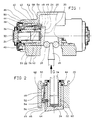
- the brake motor shown in Figure 1 is of the wedge type used in particular in drum brakes.
- This brake motor comprises in a conventional manner, a body 20 comprising two bores 22 in which are mounted pistons 24 capable of being spaced from one another by means of a wedge 26 and rollers 28 acting on the inclined bottoms 30 of the pistons 24 when the corner 26 is moved in the direction of the arrow G in FIG. 1.
- the pistons 24 by means of nuts 32 and screws 34 are capable of spreading the brake shoes to drum (not shown) thus applying the brake.
- the end 36 of the screw 34 comprises a device 38 preventing the rotation of the screw relative to the segment during the operation of the brake but allowing manual rotation of the screw 34 to screw or unscrew the latter.
- the end of the bore 22 is equipped with a protection device 40 placed between the body 20 of the brake motor and the screw 34 so as to protect the interior of the brake motor.
- the brake motor comprises an automatic adjustment device designated as a whole by the reference 42.
- the automatic adjustment 42 is formed on the one hand by the screw 34 and the nut 32, and on the other hand by a ratchet 44 associated with the nut 32 and controlled by a pawl 46 associated axially with the piston 24 by means of a pivot 48.
- the pawl 46 formed by a substantially planar plate has a first end associated with the pivot 48 so that the pawl follows the axial displacements of the piston 24, the pivot 48 being rigidly fixed to the piston 24 in a bore 49.
- the other end of the pawl 46 has a folded portion 50 of shape conjugate to the teeth of the toothed wheel 44.
- This folded portion 50 is applied elastically to the teeth by means of a spring 52 placed under a head 54 of the pivot 48 and acting radially on the pawl 46.
- the pivot 48 includes a portion 56 in the form of a portion of a sphere and forming a ball joint allowing the pawl 46 to tilt around this portion 56 against the spring 52.
- an opening 58 is made in the piston 24 so as to introduce therein a pin 59 forming a projection inside the piston and penetrating into a groove 60 formed in the nut 32 so as to limit the axial movements of the nut 32 relative to the piston 24, and keep the nut 32 - ratchet 44 assembly inside the piston 24 during any interventions on the automatic adjustment, while allowing the rotation of the nut 32 relative to the piston 24.
- the head 54 of the pivot 48 is mounted in a groove 62 formed in the body 20 of the brake motor, the diameter of the head 54 being such that the piston 24 and the pivot 48 are circumferentially positioned relative to the body 20 in which they are likely to move together axially due to this groove 62.
- the brake which has just been described operates in the following manner: when the brake motor must be actuated, a push is exerted on the corner 26 in the direction of the arrow G in FIG. 1. Under the effect of this push , the wedge enters between the two rollers 28 which roll on the one hand on the wedge 26 and on the other hand on the bottoms 30 of the pistons 24, and as the wedge and the bottoms 30 are inclined, the pistons 24 are moved apart one of the other so as to stress the brake shoes (not shown). The piston 24 shown on the left side of Figure 1 therefore moves to the left when the brake is actuated. This movement of the piston causes all of the automatic adjustment comprising, inter alia, the nut, the screw and the pawl thanks to the pivot 48.
- the movement of the pivot 48 causes the movement of the pawl 46, the ratchet 44 also moving under the thrust piston 24, the displacement of the free end of the pawl 46 relative to the teeth of the ratchet 44 being ensured by a ramp of the pawl 46 bearing on a fixed axis secured to the support 20 during the advance of the corresponding piston. If the axial progression of the piston 24 is sufficient, the portion 50 of the pawl 46 jumps a tooth of the ratchet 44 and performs the adjustment on return.
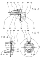
- Figures 2 and 3 show on a larger scale the piston of the brake motor of Figure 1, where the same elements have the same reference numbers. It can be seen that, according to the invention, the groove 60 is formed on the nut 32 in line with the bore 49 provided for mounting the pivot 48 when the brake motor is assembled.
- a ball 64 is introduced into the bore 49 so that it enters the groove 60.
- the ball working in shear between the edge 66 of the groove 60 and the edge 68 drilling 49 will prohibit the extraction of the nut 32 from the piston 24 during maintenance operations.
- the rotation of the nut 32 relative to the piston 24 is completely free, the ball 64 being held in place by the end of the pivot 48.
- a bore 70 is made in the pivot 48, thus putting the volume delimited by the groove 60 in communication with the external atmosphere.
- the purpose of this venting is to avoid compression of the air when the screw 34 is mounted in the nut 32.
- the threads of the screws 34 and nut 32 are lubricated with grease, as well as the bore of piston 24 in which nut 32 rotates. This therefore results in airtightness, which is detrimental to assembly or disassembly easy of the whole. This drawback is therefore eliminated thanks to the passage 70 made in the pivot 48.
- FIG. 4 a groove 60 ′ has been formed inside the bore of the piston 24, in line with the bore 49 provided for the pivot 48, and therefore opposite the groove 60 formed on the nut 32 when the latter is in its operating position.
- One or more balls 64 can therefore be introduced into the bore 49 in order to be housed in the annular volume delimited by the grooves 60 and 60 ′ at an angle a.
- the ball or balls 64 prevent the separation of the nut 32 and the piston 24, by working in shear between the edge 66 of the groove 60 of the nut 32 and the edge 68 ′ of the groove 60 ′ of the piston 24.
- the pivot 48 can penetrate more or less into the groove 60 ′ and into the groove 60, in which case the ball or balls 64 can only move over part of the volume delimited by the grooves 60 and 60 ′ at an angle a, as shown in Figures 4 and 5.
- the pivot 48 may also not enter the groove 60 ', as in the case of Figure 3, in which case the balls 64 can move in the entire volume defined by the grooves 60 and 60 ′, a volume which is as previously connected to the atmosphere by means of the hole 70 made in the pivot 48.
Landscapes
- Engineering & Computer Science (AREA)
- General Engineering & Computer Science (AREA)
- Mechanical Engineering (AREA)
- Braking Arrangements (AREA)
Claims (7)
- Selbstnachstellende Bremsbetätigungsvorrichtung (42), die ein Schraube-Mutter-System (32, 34) enthält, dessen Längenzunahme von einer ein Sperrad (44) und eine Sperrklinke (46) enthaltenden Vorrichtung gesteuert wird, die auf eine relative Axialverstellung zwischen einem Steuerkolben (24) und einem feststehenden, den Kolben (24) aufnehmenden Körper (20) anspricht, wobei die Sperrklinke (46) dem Kolben (24) über einen ein Kugelgelenk (56) bildenden Gelenkzapfen (48) zugeordnet ist, der über eine Bohrung (49) fest mit dem Kolben (24) verbunden ist, dadurch gekennzeichnet, daß die Mutter (32) eine Nut (60) aufweist, die ein ringförmiges Volumen bildet, in das wenigstens eine Kugel (64) eingebracht ist, um das Herausziehen der Mutter (32) aus dem Kolben (24) bei Wartungsarbeiten des Bremsmotors zu verhindern.
- Bremsbetätigungsvorrichtung nach Anspruch 1, dadurch gekennzeichnet, daß die Nut (60), wenn die Bremsbetätigungsvorrichtung zusammengebaut ist, auf der Mutter (32) gegenüber der zur Montage des Gelenkzapfens (48) vorgesehenen Bohrung (49) gebildet ist.
- Bremsbetätigungsvorrichtung nach Anspruch 2, dadurch gekennzeichnet, daß in die auf der Mutter gebildete Nut (60) wenigstens eine Kugel (64) durch die Bohrung (49) vor der Montage des Gelenkzapfens (48) in der Bohrung (49) eingebracht ist.
- Bremsbetätigungsvorrichtung nach Anspruch 3, dadurch gekennzeichnet, daß im Inneren einer das Schraube-Mutter-System (32, 34) aufnehmenden Bohrung des Kolbens (24) gegenüber der Bohrung (49) zur Montage des Gelenkzapfens (48) eine Nut (60') gebildet ist.
- Bremsbetätigungsvorrichtung nach Anspruch 4, dadurch gekennzeichnet, daß wenigstens eine Kugel (64) in ein ringförmiges Volumen eingebracht ist, das von den auf der Mutter (32) und dem Kolben (24) gebildeten Nuten (60, 60') abgegrenzt ist.
- Bremsbetätigungsvorrichtung nach Anspruch 5, dadurch gekennzeichnet, daß ein Ende des Gelenkzapfens (48) in das ringförmige Volumen eindringt, das von den auf der Mutter (32) und dem Kolben (24) gebildeten Nuten (60, 60') abgegrenzt ist.
- Bremsbetätigungsvorrichtung nach einem der vorangehenden Ansprüche, dadurch gekennzeichnet, daß der Gelenkzapfen (48) eine Bohrung (70) aufweist.
Applications Claiming Priority (2)
| Application Number | Priority Date | Filing Date | Title |
|---|---|---|---|
| FR9013434A FR2668565B1 (fr) | 1990-10-30 | 1990-10-30 | Moteur de frein a reglage automatique. |
| FR9013434 | 1990-10-30 |
Publications (2)
| Publication Number | Publication Date |
|---|---|
| EP0484191A1 EP0484191A1 (de) | 1992-05-06 |
| EP0484191B1 true EP0484191B1 (de) | 1994-12-07 |
Family
ID=9401696
Family Applications (1)
| Application Number | Title | Priority Date | Filing Date |
|---|---|---|---|
| EP19910402459 Expired - Lifetime EP0484191B1 (de) | 1990-10-30 | 1991-09-17 | Selbstnachstellender Bremsmotor |
Country Status (4)
| Country | Link |
|---|---|
| EP (1) | EP0484191B1 (de) |
| DE (1) | DE69105699T2 (de) |
| ES (1) | ES2065642T3 (de) |
| FR (1) | FR2668565B1 (de) |
Family Cites Families (3)
| Publication number | Priority date | Publication date | Assignee | Title |
|---|---|---|---|---|
| FR1447464A (fr) * | 1965-06-21 | 1966-07-29 | Bendix Corp | Dispositif de réglage automatique pour frein à tambour |
| FR1470078A (fr) * | 1966-02-25 | 1967-02-17 | Teves Kg Alfred | Frein hydraulique destiné notamment aux véhicules à moteur |
| FR2547004B1 (fr) * | 1983-05-31 | 1987-08-28 | Dba | Moteur de frein a reglage automatique |
-
1990
- 1990-10-30 FR FR9013434A patent/FR2668565B1/fr not_active Expired - Lifetime
-
1991
- 1991-09-17 ES ES91402459T patent/ES2065642T3/es not_active Expired - Lifetime
- 1991-09-17 EP EP19910402459 patent/EP0484191B1/de not_active Expired - Lifetime
- 1991-09-17 DE DE1991605699 patent/DE69105699T2/de not_active Expired - Fee Related
Also Published As
| Publication number | Publication date |
|---|---|
| DE69105699D1 (de) | 1995-01-19 |
| DE69105699T2 (de) | 1995-04-13 |
| FR2668565A1 (fr) | 1992-04-30 |
| ES2065642T3 (es) | 1995-02-16 |
| FR2668565B1 (fr) | 1992-12-24 |
| EP0484191A1 (de) | 1992-05-06 |
Similar Documents
| Publication | Publication Date | Title |
|---|---|---|
| EP0250285B1 (de) | Bremsmotor mit einer rückstellbaren automatischen Nachstellvorrichtung | |
| EP0145535B1 (de) | Automatisch regulierter Bremsmotor | |
| EP0028955B1 (de) | Schwimmsattel-Scheibenbremse | |
| WO2000053374A1 (fr) | Procede de pose d'un collier elastique et outillages le mettant en oeuvre | |
| EP0133389A1 (de) | Scheibenbremse mit abnehmbarem Verstärkungssattelarm | |
| EP0249522B1 (de) | Selbsttätig nachstellende Bremsbetätigungsvorrichtung | |
| EP3087285B1 (de) | Verbesserte scheibenbremse mit einer hydraulisch betätigten feststellbremse und einer verschleisseinstellungseinheit | |
| EP0734496B1 (de) | Automatisch nachstellbare strebe für eine trommelbremse | |
| EP3087286B1 (de) | Scheibenbremse mit einer parkbremse mit hydraulischer betätigung | |
| EP0484191B1 (de) | Selbstnachstellender Bremsmotor | |
| EP0128081B1 (de) | Automatisch regulierter Bremsmotor | |
| EP0172064B1 (de) | Scheibenbremse | |
| FR2537230A2 (fr) | Dispositif de reglage automatique pour frein | |
| EP0151070B1 (de) | Selbsttätig nachstellende Bremsbetätigungsvorrichtung | |
| EP1228320A1 (de) | Rampe mit kugeln sowie bremszylinder mit einer solchen rampe | |
| FR2600734A1 (fr) | Dispositif de reglage automatique pour frein a disque. | |
| FR2676490A1 (fr) | Dispositif de surete apte a realiser un blocage du barillet en cas de tentative de forcage et mecanisme de serrure equipe de ce dispositif. | |
| FR2809463A1 (fr) | Agencement de transmission d'entrainement a accouplement a roue libre | |
| EP0725709B1 (de) | Schraubenschlüssel | |
| EP0531178A1 (de) | Selbsttätige Nachstellvorrichtung für einen Bremsmechanismus | |
| EP0326774A1 (de) | Scheibenbremse und Bremsbacke dafür | |
| FR2778712A1 (fr) | Dispositif de rattrapage d'usure notamment pour un frein de vehicule | |
| EP3087290B1 (de) | Scheibenbremse mit einer feststellbremse mit verbesserter hydraulischer betätigung | |
| EP0167415B1 (de) | Drehmomentbegrenzer | |
| EP0907035A1 (de) | Strebe mit automatischer Verschleissnachstellung für eine Trommelbremse sowie mit einer solchen Strebe ausgerüstete Trommelbremse |
Legal Events
| Date | Code | Title | Description |
|---|---|---|---|
| PUAI | Public reference made under article 153(3) epc to a published international application that has entered the european phase |
Free format text: ORIGINAL CODE: 0009012 |
|
| AK | Designated contracting states |
Kind code of ref document: A1 Designated state(s): DE ES FR GB IT |
|
| 17P | Request for examination filed |
Effective date: 19920519 |
|
| 17Q | First examination report despatched |
Effective date: 19930727 |
|
| RAP1 | Party data changed (applicant data changed or rights of an application transferred) |
Owner name: ALLIEDSIGNAL EUROPE SERVICES TECHNIQUES |
|
| GRAA | (expected) grant |
Free format text: ORIGINAL CODE: 0009210 |
|
| AK | Designated contracting states |
Kind code of ref document: B1 Designated state(s): DE ES FR GB IT |
|
| ITF | It: translation for a ep patent filed | ||
| REF | Corresponds to: |
Ref document number: 69105699 Country of ref document: DE Date of ref document: 19950119 |
|
| GBT | Gb: translation of ep patent filed (gb section 77(6)(a)/1977) |
Effective date: 19950110 |
|
| REG | Reference to a national code |
Ref country code: ES Ref legal event code: FG2A Ref document number: 2065642 Country of ref document: ES Kind code of ref document: T3 |
|
| PLBE | No opposition filed within time limit |
Free format text: ORIGINAL CODE: 0009261 |
|
| STAA | Information on the status of an ep patent application or granted ep patent |
Free format text: STATUS: NO OPPOSITION FILED WITHIN TIME LIMIT |
|
| 26N | No opposition filed | ||
| PGFP | Annual fee paid to national office [announced via postgrant information from national office to epo] |
Ref country code: GB Payment date: 19960808 Year of fee payment: 6 |
|
| PGFP | Annual fee paid to national office [announced via postgrant information from national office to epo] |
Ref country code: FR Payment date: 19960910 Year of fee payment: 6 |
|
| PGFP | Annual fee paid to national office [announced via postgrant information from national office to epo] |
Ref country code: ES Payment date: 19960920 Year of fee payment: 6 |
|
| PGFP | Annual fee paid to national office [announced via postgrant information from national office to epo] |
Ref country code: DE Payment date: 19960927 Year of fee payment: 6 |
|
| PG25 | Lapsed in a contracting state [announced via postgrant information from national office to epo] |
Ref country code: GB Free format text: LAPSE BECAUSE OF NON-PAYMENT OF DUE FEES Effective date: 19970917 |
|
| PG25 | Lapsed in a contracting state [announced via postgrant information from national office to epo] |
Ref country code: ES Free format text: LAPSE BECAUSE OF THE APPLICANT RENOUNCES Effective date: 19970918 |
|
| PG25 | Lapsed in a contracting state [announced via postgrant information from national office to epo] |
Ref country code: FR Free format text: THE PATENT HAS BEEN ANNULLED BY A DECISION OF A NATIONAL AUTHORITY Effective date: 19970930 |
|
| GBPC | Gb: european patent ceased through non-payment of renewal fee |
Effective date: 19970917 |
|
| PG25 | Lapsed in a contracting state [announced via postgrant information from national office to epo] |
Ref country code: DE Free format text: LAPSE BECAUSE OF NON-PAYMENT OF DUE FEES Effective date: 19980603 |
|
| REG | Reference to a national code |
Ref country code: FR Ref legal event code: ST |
|
| REG | Reference to a national code |
Ref country code: ES Ref legal event code: FD2A Effective date: 20001009 |
|
| PG25 | Lapsed in a contracting state [announced via postgrant information from national office to epo] |
Ref country code: IT Free format text: LAPSE BECAUSE OF NON-PAYMENT OF DUE FEES;WARNING: LAPSES OF ITALIAN PATENTS WITH EFFECTIVE DATE BEFORE 2007 MAY HAVE OCCURRED AT ANY TIME BEFORE 2007. THE CORRECT EFFECTIVE DATE MAY BE DIFFERENT FROM THE ONE RECORDED. Effective date: 20050917 |