EP0484162A2 - Method and apparatus for conveying molten glass - Google Patents
Method and apparatus for conveying molten glass Download PDFInfo
- Publication number
- EP0484162A2 EP0484162A2 EP91310082A EP91310082A EP0484162A2 EP 0484162 A2 EP0484162 A2 EP 0484162A2 EP 91310082 A EP91310082 A EP 91310082A EP 91310082 A EP91310082 A EP 91310082A EP 0484162 A2 EP0484162 A2 EP 0484162A2
- Authority
- EP
- European Patent Office
- Prior art keywords
- channel
- nozzle
- molten glass
- heating fluid
- heating
- Prior art date
- Legal status (The legal status is an assumption and is not a legal conclusion. Google has not performed a legal analysis and makes no representation as to the accuracy of the status listed.)
- Withdrawn
Links
Images
Classifications
-
- C—CHEMISTRY; METALLURGY
- C03—GLASS; MINERAL OR SLAG WOOL
- C03B—MANUFACTURE, SHAPING, OR SUPPLEMENTARY PROCESSES
- C03B7/00—Distributors for the molten glass; Means for taking-off charges of molten glass; Producing the gob, e.g. controlling the gob shape, weight or delivery tact
- C03B7/02—Forehearths, i.e. feeder channels
- C03B7/06—Means for thermal conditioning or controlling the temperature of the glass
Definitions
- the present invention relates to molten glass conveying apparatus and methods of conveying molten glass.
- the invention is described with respect to its applicability in glass forehearths. However, the invention is not limited to these forehearths since it additionally finds uses in, for instance, the working ends of glass manufacturing furnaces.
- the forehearth is located between a glass melting tank and a feeder bowl which provides molten gobs to be fed into glassware forming machines.
- a typical forehearth comprises a refractory channel along which the molten glass flows and which is provided with an insulating roof.
- the temperature of the glass is not homogeneous throughout its cross-section.
- the glass tends to be cooler at its side portions compared to the temperature of the molten glass at the centre of the channel. This is due to the cooling effect of the side walls of the channel.
- the temperature differences result in differing viscosities which themselves result in a range of molten glass velocities across the channel. It is also normally a requirement that the molten glass be at a lower temperature than the furnace exit temperature.
- a heating fluid e.g a gas-air flame
- nozzles which fire the heating fluid from the side walls of the forehearth transverse to the direction of flow of the molten glass or, as in the case of US 1 893 061 (Peiler) a nozzle in an angled, complex section of the roof of the forehearth which directs the heating fluid into a firing chamber constituted by a space above the molten glass adjacent to the feed spout, the heating fluid then passes rearwardly along the surface of the glass in opposite side portions of the forehearth channel to stacks which induce the flow of the gasses out to the atmosphere.
- a heating fluid e.g a gas-air flame
- the side burner arrangements in the prior proposals require a plurality of burners for a short section of forehearth and the flames from the burners may extend to the centre of the glass stream resulting in the need for extra cooling of the centre of the glass stream.
- the roof firing arrangement suggested in US 1 893 061 (Peiler) requires a complex refractory arrangement and detailed management of the stacks to control the molten glass temperature.
- the required cooling is achieved in several ways, for instance, by radiation from openings in the sides or roof, by air jets fired from the side walls directed onto the central region of the internal roof structure, longitudinal air flows on the inside of the centre of the roof along the channel or from longirudinal air flows on the outside of the centre of the roof. All except the first of these methods of cooling act by reducing the temperature of the central portion of the roof refractory and by the roof absorbing heat from the glass.
- a molten glass conveying apparatus comprising a channel along which molten glass may flow, a roof structure over the channel and extending between the two sides thereof and at least one nozzle in the roof structure through which a heating fluid may be passed, wherein in use the direction of the output of the heating fluid from the nozzle is substantially along the channel whereby at leat one side portion of the molten glass is heated.
- a method of conveying molten glass along a channel comprising passing a heating fluid through at least one nozzle in a roof structure over the channel, wherein roof structure extends between the two sides of the channel,wherein the direction of the output of the heating fluid from the nozzle is substantially along the channel whereby at least one side portion of the molten glass is heated.
- the vector component of the output of the heating fluid along the channel is at leats twice the magnitude of the other vector components.
- said at least one nozzle for the heating fluid is provided in a roof member of the roof structure.
- At least one nozzle is provided through which a cooling fluid may be passed, and, in use, the direction of the output of the fluid from the cooling fluid nozzle is substantially along the channel whereby the central portion of the molten glass is cooled.
- At least two nozzles for heating fluid are provided in the roof member spaced substantially symmetrically on each side of the or each cooling fluid nozzle.
- the roof member rests directly upon the two side walls of the channel.
- one or more of the nozzles make use of the coanda effect.
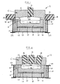
- a forehearth 2 comprising an elongate channel 4 which is defined between a roof structure 6 and an elongate, cross-sectionally U-shaped refractory member 8.
- the refractory member 8 is supported by secondary elongate refractory members 10 which are rectangular in cross-section.
- the roof structure 6 comprises an elongate roof member 12 which is a truncated n-section and extends between the two sides of the channel 4 and two elongate side walls 14 which are rectangular in cross-section.
- the roof member 12 and side walls 14 are made from refractory materials.
- the roof member 12 Near the working end of the forehearth 2, where the molten glass enters the forehearth, the roof member 12 has a centrally located cooling unit 16.
- the cooling unit 16 is substantially identical to the heating units 18, although each of the units 16, 18 is independently controlled.
- the entire forehearth 2 is supported by an elongate support member 20 which itself is maintained between two elongate I-section bars 22.
- the glass is melted in a melting station and then flows to the working ends and then through the forehearth 2 where the molten glass 24 is conditioned.
- the refractory 8 is therefore formed from a material that reacts as little as possible with the molten glass 24 at the conditioning temperatures.
- the molten glass 24 is heated at its side portions and cooled along its central region.
- the heating is carried out by heating units 18; the cooling by cooling unit 16.
- These units 16, 18 are supplied with a combustible gas (e.g propane) and air to support combustion from gas supply cylinders (not shown).
- a combustible gas e.g propane
- gas supply cylinders not shown
- Each unit 16, 18 projects a flame constituted by the ignited gases along the channel, i.e the direction of the flame is such that the vector component of the flame longitudinally in the channel is greater than each of the vector components in directions orthogonal to the longitudinal axis of the channel.
- the longitudinal component will be greater than twice the magnitude of each of the other components.
- the flame constituted by the ignited gases will be substantially along the roof of the channel.
- the heating fluid is projected along the channel either in a direction that is the same as the glass flow or against it in at least one vector component the flow of heating fluid does not include vector components in both said directions.
- the direction of the output of heating fluid from the nozzle is determined by making a series of ten measurements of the heating fluid over a period of time. A photographic or video image is produced of the ignited heating fluid in the channel. The point at which part of the ignited heating fluid is furthest from the centre of the exit of the nozzle is established and the vector quantity between these two points comprises a single measurement. An average (mean) of ten of these measurements over a period of time during which all other factors are nominally constant gives a direction of the output of the heating fluid from the nozzle 28.
- the gas and air are supplied under pressure to the unit and ejected into the open volume 26 of the channel 4; through a nozzle 28 the output part of which is shown in figure 2.
- the nozzle 28 can be seen in the heating unit 18.
- the channel of the nozzle comprises a wide section 30 a narrowing section 32 and an exit 34.
- the gas and air mix is pumped, under pressure into the wide section 30 of the nozzle 28 and a jet of the gas-air mix is produced along the narrowing section 32 so that the heating fluid flows out of the exit 34 at an increased speed.
- the gas-air mixture is ignited before it exits the nozzle by a standard lighting means (not shown).
- the gas-air mixture that constitutes the heating fluid is projected along the open volume 26 making use of the natural phenomenon known as the 'Coanda effect' which is the term given to the tendency of a fluid jet to attach itself to a downstream surface roughly parallel to the jet axis. If this surface curves away from the jet the attached flow will follow it, deflecting from the original direction.
- a jet can be introduced into the unit at a given angle to the longitudinal axis of the channel, and its direction changed using the Coanda effect so that the jet emitted from the nozzle 28 is along the channel.
- the fluid flow conditions of the heating fluid and the configuration of the nozzle 28 determine the direction of the output of heating fluid from the nozzle 28 in a manner which can be readily determined by those skilled in the art.
- the heating units 18 are located in the side walls 14 of the forehearth 2. Using the Coanda effect the heating fluid may be projected along the channel close to the side walls thus heating the side portions of the molten glass. Effectively, the flame is fired along the channel.
- the temperature of the heating fluid can be controlled by varying the mixture of gas and air supplied to the nozzle 28, as is well known in the art.
- the cooling unit 16 operates in a similar fashion at a lower temperature.
- the fluid flow may comprise a flow of air without any flammable gas.
- the roof member 12 may include a corridor along which the cooling fluid may flow. The direction of a non-ignited cooling fluid may be determined by substituting that fluid for a heating fluid, igniting it and using the method of measurement described hereinabove.
- the temperature of the molten glass is determined either by optical pyrometers or thermocouples ( neither shown ) in the channel 4. These instruments are monitored to determine the occurrence of any temperature differentials which can then be equalised using the cooling and/or heating units 16, 18.
- the instrument monitoring and temperature control can be carried out by a computer to enable the forehearth to be automated.
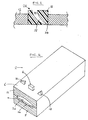
- FIG. 3 and 4 of the drawings that follow shows a molten glass channel with a roof member 12 over the channel extending between the two sides thereof.
- the roof member 12 is shown resting directly on the U-shaped refractory member 8 it is possible for various sizes of side walls 14 to be used to space the roof member 12 from the molten glass 24.
- cooling and heating units 16, 18 are located in the roof member 12. Again the Coanda effect is used to project the heating fluid substantially along the channel so that the heating units heat the side portions of the molten glass whilst the cooling unit cools the central region.
- This embodiment has the advantage that the space between the glass 24 and the roof member 12 is substantially reduced thereby enabling better control of the molten glass temperature.
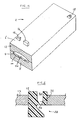
- the third embodiment shown in figure 5 of the drawings that follows includes a heating unit 18 located at the upstream end of the conditioning zone of the forehearth 2.
- This heating unit 18 projects its heating fluid upstream (relative to the direction of flow of the molten glass 24) along the channel allowing a recirculating heating mode.
- Many similar arrangements of upstream and downstream firing cooling and heating units 16, 18 can be utilised.
- a heating or cooling unit can be located both at the upstream and downstream ends of the forehearth 2. The actual placement of the units will depend on the field results for the furnace and conditions used.
- this third embodiment has the advantage that the roof member 12 can be close to the molten glass 24.
- Nozzles using the Coanda effect have the advantage that there does not need to be any projection of the nozzle structure into the channel 4. This simplifies the flow conditions in the channel.
- the invention is not limited to the use of Coanda effect burners.
- Other heating means can be readily employed to cause the direction of the output of the heating fluid from the nozzle to be substantially along the channel.
- a nozzle can be used having the construction shown in figure 6 of the drawings that follow. This is a conventional jet nozzle with a deflector plate 36 formed of a refractory material. The deflector plate 36 causes the flow of heating fluid to be projected along the channel 4. The deflector plates forms part of the nozzle 28 since the direction of the heating fluid is substantially governed by the nozzle 28. The path of the heating fluid is substantially unidirectional once it has left the nozzle 28.
- Other nozzle designs may be used to achieve the same effect in the present invention.
- the invention is not limited to this embodiment. Any of the conventional methods of cooling discussed above may be used in a molten glass conveying apparatus according to the present invention.
- thermoelectric heating can be used in the refractory member 8 to reduce the cooling of the side portions of the molten glass 24.
- the forehearth 2 can comprise several sections each of which may include a heating means according to the present invention.
- heating means according to the present invention may be combined with conventional heating means in one or more sections of the forehearth.
- roof structure 6 is normally substantially parallel to the molten glass surface longitudinally along the channel along, at least, that part of the channel between the nozzle 28 and the furthest extremity reached by the heating fluid.
- a combustion, or burner chamber is not required reducing the complexity of the roof structure 6 and allowing more favourable control of the temperature conditions within the forehearth.
- the present invention provides a glass conveying apparatus and method which reduces the number of burners required for a given section of the forehearth, enables heating of the molten glass without the flames extending to the centre of the glass stream allow simpler and cheaper refractory and burner equipment to be used, with roof firing the side walls can be more adequately insulated and even with side-wall firing the reduction in the number of burners allows the side-walls to be more adequately insulated in this case as well. Furthermore, the present invention allows the provision for heat recovery equipment alongside the heating means to be more easily and conveniently arranged.
Landscapes
- Chemical & Material Sciences (AREA)
- Physics & Mathematics (AREA)
- Thermal Sciences (AREA)
- Engineering & Computer Science (AREA)
- Materials Engineering (AREA)
- Organic Chemistry (AREA)
- Furnace Details (AREA)
- Glass Melting And Manufacturing (AREA)
Abstract
Description
- The present invention relates to molten glass conveying apparatus and methods of conveying molten glass.
- The invention is described with respect to its applicability in glass forehearths. However, the invention is not limited to these forehearths since it additionally finds uses in, for instance, the working ends of glass manufacturing furnaces.
- The forehearth is located between a glass melting tank and a feeder bowl which provides molten gobs to be fed into glassware forming machines. A typical forehearth comprises a refractory channel along which the molten glass flows and which is provided with an insulating roof.
- It is known that the temperature of the glass is not homogeneous throughout its cross-section. The glass tends to be cooler at its side portions compared to the temperature of the molten glass at the centre of the channel. This is due to the cooling effect of the side walls of the channel. The temperature differences result in differing viscosities which themselves result in a range of molten glass velocities across the channel. It is also normally a requirement that the molten glass be at a lower temperature than the furnace exit temperature.
- In practice it has been found that to overcome the problem outlined above the side portions of the stream of molten glass require heating whilst the centre portion requires cooling.
- Various suggestions for achieving the heating and cooling of the portions of the molten glass stream are made in the following patent specifications: GB 1 452 351 (Societe Generale Pour L'Emballage), UK 355 555 (Jackson), EP 0 145 427 (Emhart), EP 0 275 345 (Emhart), US 1 893 061 (Peiler), US 1 970 094 (Honiss), US 3 582 310 (Avery), US 3 999 972 (Brax), WO 83/01440 (BHF) and DE 3 119 816 (Sorg).
- The proposals that involve the use of a heating fluid (e.g a gas-air flame) above the molten glass have nozzles which fire the heating fluid from the side walls of the forehearth transverse to the direction of flow of the molten glass or, as in the case of US 1 893 061 (Peiler) a nozzle in an angled, complex section of the roof of the forehearth which directs the heating fluid into a firing chamber constituted by a space above the molten glass adjacent to the feed spout, the heating fluid then passes rearwardly along the surface of the glass in opposite side portions of the forehearth channel to stacks which induce the flow of the gasses out to the atmosphere.
- The side burner arrangements in the prior proposals require a plurality of burners for a short section of forehearth and the flames from the burners may extend to the centre of the glass stream resulting in the need for extra cooling of the centre of the glass stream. The roof firing arrangement suggested in US 1 893 061 (Peiler) requires a complex refractory arrangement and detailed management of the stacks to control the molten glass temperature.
- The required cooling is achieved in several ways, for instance, by radiation from openings in the sides or roof, by air jets fired from the side walls directed onto the central region of the internal roof structure, longitudinal air flows on the inside of the centre of the roof along the channel or from longirudinal air flows on the outside of the centre of the roof. All except the first of these methods of cooling act by reducing the temperature of the central portion of the roof refractory and by the roof absorbing heat from the glass.
- According to a first aspect of the present invention there is provided a molten glass conveying apparatus comprising a channel along which molten glass may flow, a roof structure over the channel and extending between the two sides thereof and at least one nozzle in the roof structure through which a heating fluid may be passed, wherein in use the direction of the output of the heating fluid from the nozzle is substantially along the channel whereby at leat one side portion of the molten glass is heated.
- According to a second aspect of the present invention there is provided a method of conveying molten glass along a channel comprising passing a heating fluid through at least one nozzle in a roof structure over the channel, wherein roof structure extends between the two sides of the channel,wherein the direction of the output of the heating fluid from the nozzle is substantially along the channel whereby at least one side portion of the molten glass is heated.
- Preferably the vector component of the output of the heating fluid along the channel is at leats twice the magnitude of the other vector components.
- Preferably said at least one nozzle for the heating fluid is provided in a roof member of the roof structure.
- Preferably at least one nozzle is provided through which a cooling fluid may be passed, and, in use, the direction of the output of the fluid from the cooling fluid nozzle is substantially along the channel whereby the central portion of the molten glass is cooled.
- Preferably in the apparatus described above, at least two nozzles for heating fluid are provided in the roof member spaced substantially symmetrically on each side of the or each cooling fluid nozzle.
- Suitably in apparatus described in the paragraph above the roof member rests directly upon the two side walls of the channel.
- In any of the above apparatus it is preferred that one or more of the nozzles make use of the coanda effect.
- Most suitably, all nozzles make use of the coanda effect.
- The invention will now be described, by way of example only, with reference to the following drawings, wherein:
- Figure 1 is a schematic cross-sectional view of a forehearth according to a first embodiment of the present invention ;
- Figure 2 is a schematic cross-sectional view along the line II-II in Figure1;
- Figure 3 is a schematic cross-sectional view of a forehearth according to a second embodiment of the present invention;
- Figure 4 is a diagrammatic perspective view of the forehearth illustrated in figure 3;
- Figure 5 is a diagrammatic perspective view of a forehearth according to a third embodiment of the present invention; and;
- Figure 6 is a schematic cross-sectional view similar to figure 2, showing an alternative nozzle design.
- Referring now to figure 1 of the drawings that follow, there is shon a
forehearth 2 comprising anelongate channel 4 which is defined between aroof structure 6 and an elongate, cross-sectionally U-shapedrefractory member 8. Therefractory member 8 is supported by secondary elongaterefractory members 10 which are rectangular in cross-section. - Contained in the
channel 4 there is shown a mass ofmolten glass 24, above which is shown anopen volume 26 within thechannel 4. - The
roof structure 6 comprises anelongate roof member 12 which is a truncated n-section and extends between the two sides of thechannel 4 and twoelongate side walls 14 which are rectangular in cross-section. Theroof member 12 andside walls 14 are made from refractory materials. Near the working end of theforehearth 2, where the molten glass enters the forehearth, theroof member 12 has a centrally locatedcooling unit 16. Similarly, there areheating units 18 located on each of theside walls 14 near the working end of theforehearth 2. In this case thecooling unit 16 is substantially identical to theheating units 18, although each of theunits - The
entire forehearth 2 is supported by anelongate support member 20 which itself is maintained between two elongate I-section bars 22. - The method of operation of the embodiment of the present invention shown in figure 1 will now be described.
- The glass is melted in a melting station and then flows to the working ends and then through the
forehearth 2 where themolten glass 24 is conditioned. Therefractory 8 is therefore formed from a material that reacts as little as possible with themolten glass 24 at the conditioning temperatures. - To provide as homogeneous a glass flow as possible the
molten glass 24 is heated at its side portions and cooled along its central region. The heating is carried out byheating units 18; the cooling bycooling unit 16. - These
units - Each
unit - The direction of the output of heating fluid from the nozzle is determined by making a series of ten measurements of the heating fluid over a period of time. A photographic or video image is produced of the ignited heating fluid in the channel. The point at which part of the ignited heating fluid is furthest from the centre of the exit of the nozzle is established and the vector quantity between these two points comprises a single measurement. An average (mean) of ten of these measurements over a period of time during which all other factors are nominally constant gives a direction of the output of the heating fluid from the
nozzle 28. - As the cooling and
heating units typical heating unit 18 will be described. The gas and air are supplied under pressure to the unit and ejected into theopen volume 26 of thechannel 4; through anozzle 28 the output part of which is shown in figure 2. Thenozzle 28 can be seen in theheating unit 18. The channel of the nozzle comprises a wide section 30 anarrowing section 32 and anexit 34. The gas and air mix is pumped, under pressure into thewide section 30 of thenozzle 28 and a jet of the gas-air mix is produced along the narrowingsection 32 so that the heating fluid flows out of theexit 34 at an increased speed. - The gas-air mixture is ignited before it exits the nozzle by a standard lighting means (not shown). The gas-air mixture that constitutes the heating fluid is projected along the
open volume 26 making use of the natural phenomenon known as the 'Coanda effect' which is the term given to the tendency of a fluid jet to attach itself to a downstream surface roughly parallel to the jet axis. If this surface curves away from the jet the attached flow will follow it, deflecting from the original direction. Thus in the present case a jet can be introduced into the unit at a given angle to the longitudinal axis of the channel, and its direction changed using the Coanda effect so that the jet emitted from thenozzle 28 is along the channel. The fluid flow conditions of the heating fluid and the configuration of thenozzle 28 determine the direction of the output of heating fluid from thenozzle 28 in a manner which can be readily determined by those skilled in the art. - In this embodiment the
heating units 18 are located in theside walls 14 of theforehearth 2. Using the Coanda effect the heating fluid may be projected along the channel close to the side walls thus heating the side portions of the molten glass. Effectively, the flame is fired along the channel. The temperature of the heating fluid can be controlled by varying the mixture of gas and air supplied to thenozzle 28, as is well known in the art. - The cooling
unit 16 operates in a similar fashion at a lower temperature. The fluid flow may comprise a flow of air without any flammable gas. Theroof member 12 may include a corridor along which the cooling fluid may flow. The direction of a non-ignited cooling fluid may be determined by substituting that fluid for a heating fluid, igniting it and using the method of measurement described hereinabove. - The temperature of the molten glass is determined either by optical pyrometers or thermocouples ( neither shown ) in the
channel 4. These instruments are monitored to determine the occurrence of any temperature differentials which can then be equalised using the cooling and/orheating units - The remaining embodiments of the present invention operate in much the same fashion as the first embodiment and require only a brief explanation to facilitate understanding by those skilled in the art. The components are substantially identical, they are simply repositioned. In these latter embodiments like numerals identify like parts.
- Figures 3 and 4 of the drawings that follow shows a molten glass channel with a
roof member 12 over the channel extending between the two sides thereof. Although in this case theroof member 12 is shown resting directly on the U-shapedrefractory member 8 it is possible for various sizes ofside walls 14 to be used to space theroof member 12 from themolten glass 24. - In this second embodiment the cooling and
heating units roof member 12. Again the Coanda effect is used to project the heating fluid substantially along the channel so that the heating units heat the side portions of the molten glass whilst the cooling unit cools the central region. - This embodiment has the advantage that the space between the
glass 24 and theroof member 12 is substantially reduced thereby enabling better control of the molten glass temperature. - The third embodiment shown in figure 5 of the drawings that follows includes a
heating unit 18 located at the upstream end of the conditioning zone of theforehearth 2. Thisheating unit 18 projects its heating fluid upstream (relative to the direction of flow of the molten glass 24) along the channel allowing a recirculating heating mode. Many similar arrangements of upstream and downstream firing cooling andheating units forehearth 2. The actual placement of the units will depend on the field results for the furnace and conditions used. - Again this third embodiment has the advantage that the
roof member 12 can be close to themolten glass 24. - Nozzles using the Coanda effect have the advantage that there does not need to be any projection of the nozzle structure into the
channel 4. This simplifies the flow conditions in the channel. - However, the invention is not limited to the use of Coanda effect burners. Other heating means can be readily employed to cause the direction of the output of the heating fluid from the nozzle to be substantially along the channel. For instance, a nozzle can be used having the construction shown in figure 6 of the drawings that follow. This is a conventional jet nozzle with a deflector plate 36 formed of a refractory material. The deflector plate 36 causes the flow of heating fluid to be projected along the
channel 4. The deflector plates forms part of thenozzle 28 since the direction of the heating fluid is substantially governed by thenozzle 28. The path of the heating fluid is substantially unidirectional once it has left thenozzle 28. Other nozzle designs may be used to achieve the same effect in the present invention. - Although the Coanda effect can be used to advantage in the
cooling unit 16 the invention is not limited to this embodiment. Any of the conventional methods of cooling discussed above may be used in a molten glass conveying apparatus according to the present invention. - Furthermore, other methods of heating may be used to assist the heating caused by the present invention. For instance, electrical heating can be used in the
refractory member 8 to reduce the cooling of the side portions of themolten glass 24. - It should be noted that the
forehearth 2 can comprise several sections each of which may include a heating means according to the present invention. Alternatively, heating means according to the present invention may be combined with conventional heating means in one or more sections of the forehearth. - It should also be noted that the
roof structure 6 is normally substantially parallel to the molten glass surface longitudinally along the channel along, at least, that part of the channel between thenozzle 28 and the furthest extremity reached by the heating fluid. Thus a combustion, or burner chamber is not required reducing the complexity of theroof structure 6 and allowing more favourable control of the temperature conditions within the forehearth. - Thus the present invention provides a glass conveying apparatus and method which reduces the number of burners required for a given section of the forehearth, enables heating of the molten glass without the flames extending to the centre of the glass stream allow simpler and cheaper refractory and burner equipment to be used, with roof firing the side walls can be more adequately insulated and even with side-wall firing the reduction in the number of burners allows the side-walls to be more adequately insulated in this case as well. Furthermore, the present invention allows the provision for heat recovery equipment alongside the heating means to be more easily and conveniently arranged.
Claims (8)
- A molten glass conveying apparatus comprising a channel along which molten glass may flow, a roof structure over the channel and extending between the two sides thereof and at least one nozzle in the roof structure through which a heating fluid may be passed, wherein in use the direction of the output of the heating fluid from the nozzle is substantially along the channel whereby at least one side portion of the molten glass is heated.
- Apparatus as claimed in Claim 1, wherein the vector component of the output of the heating fluid along the channel is as least twice the magnitude of the other vector components.
- Apparatus as claimed in Claim 1 or Claim 2, wherein said at least one nozzle for the heating fluid is provided in a roof member of the roof structure.
- Apparatus as claimed in Claim 1, 2 or 3, wherein at least one nozzle is provided through which a cooling fluid may be passed, and, in use, the direction of the output of the fluid from the cooling fluid nozzle is substantially along the channel whereby the central portion of the molten glass is cooled.
- Apparatus as claimed in Claim 4 wherein at least two nozzles for heating fluid are provided in the roof member spaced substantially symmetrically on each side of the or each nozzle for the cooling fluid.
- Apparatus as claimed in Claim 5, wherein the roof member rests directly upon the two side walls of the channel.
- Apparatus as claimed in any preceding claim, wherein one or more of said nozzles makes use of the coanda effect.
- A method of conveying molten glass along the channel comprising passing a heating fluid through at least one nozzle in a roof structure over the channel, which roof structure extends between the two sides of the channel, wherein the direction of the output of the heating fluid from the nozzle is substantially along the channel whereby at least one side portion of the molten glass is heated.
Applications Claiming Priority (2)
| Application Number | Priority Date | Filing Date | Title |
|---|---|---|---|
| GB9023638 | 1990-10-31 | ||
| GB909023638A GB9023638D0 (en) | 1990-10-31 | 1990-10-31 | Method and apparatus for conveying molten glass |
Publications (2)
| Publication Number | Publication Date |
|---|---|
| EP0484162A2 true EP0484162A2 (en) | 1992-05-06 |
| EP0484162A3 EP0484162A3 (en) | 1993-01-13 |
Family
ID=10684619
Family Applications (1)
| Application Number | Title | Priority Date | Filing Date |
|---|---|---|---|
| EP19910310082 Withdrawn EP0484162A3 (en) | 1990-10-31 | 1991-10-31 | Method and apparatus for conveying molten glass |
Country Status (3)
| Country | Link |
|---|---|
| US (1) | US5198010A (en) |
| EP (1) | EP0484162A3 (en) |
| GB (1) | GB9023638D0 (en) |
Families Citing this family (4)
| Publication number | Priority date | Publication date | Assignee | Title |
|---|---|---|---|---|
| US5718741A (en) * | 1995-05-19 | 1998-02-17 | Owens-Brockway Glass Container Inc. | Directly cooled, side fired forehearth |
| US6044667A (en) * | 1997-08-25 | 2000-04-04 | Guardian Fiberglass, Inc. | Glass melting apparatus and method |
| US8113018B2 (en) * | 2006-12-14 | 2012-02-14 | Ocv Intellectual Capital, Llc | Apparatuses for controlling the temperature of glass forming materials in forehearths |
| IT1391154B1 (en) * | 2008-08-07 | 2011-11-18 | F I R E S R L | CHANNEL OR DISTRIBUTOR FOR GLASS OVEN AND SMOKE EXTRACTION PROCEDURE FROM THE CHANNEL |
Family Cites Families (14)
| Publication number | Priority date | Publication date | Assignee | Title |
|---|---|---|---|---|
| US1909152A (en) * | 1920-03-31 | 1933-05-16 | Hartford Empire Co | Apparatus for feeding molten glass |
| US1644893A (en) * | 1925-09-01 | 1927-10-11 | Hartford Empire Co | Feeding molten glass |
| US1970113A (en) * | 1928-05-08 | 1934-08-14 | Hartford Empire Co | Forehearth for glass melting furnaces and method of conditioning molten glass |
| US1879718A (en) * | 1929-04-17 | 1932-09-27 | Owens Illinois Glass Co | Glass furnace |
| US1893061A (en) * | 1929-09-19 | 1933-01-03 | Hartford Empire Co | Forehearth for molten glass |
| GB355555A (en) * | 1930-09-27 | 1931-08-27 | Hartford Empire Co | Improvements in forehearths for glass melting furnaces |
| US2767518A (en) * | 1953-01-13 | 1956-10-23 | Arthur W Schmid | Forehearth structure |
| US2771711A (en) * | 1954-08-27 | 1956-11-27 | Cie Reunies Glaces Et Verres | Apparatus for conditioning glass which is to be continuously drawn into sheets |
| US3475151A (en) * | 1966-06-22 | 1969-10-28 | Honeywell Inc | Cyclic burner controlling apparatus for glass melting furnace |
| US3856496A (en) * | 1973-01-26 | 1974-12-24 | Leone Int Sales Corp | Glass melting furnace and process |
| US4294603A (en) * | 1979-09-04 | 1981-10-13 | Emhart Industries, Inc. | Glass forehearth construction |
| FR2567118B1 (en) * | 1984-07-04 | 1986-11-14 | Air Liquide | METHOD FOR HEATING A GLASS CONTAINING CHANNEL USING OXY-FUEL FLAMES |
| US4655812A (en) * | 1985-09-16 | 1987-04-07 | Emhart Industries, Inc. | Electric heating of glass forehearth |
| ATE41405T1 (en) * | 1985-09-24 | 1989-04-15 | Himly Holscher Gmbh & Co | PROCEDURE FOR EQUALIZING THE TEMPERATURE ACROSS THE CROSS SECTION OF A GLASS STREAM AND PRIOR TO CARRYING OUT THE PROCESS. |
-
1990
- 1990-10-31 GB GB909023638A patent/GB9023638D0/en active Pending
-
1991
- 1991-10-31 EP EP19910310082 patent/EP0484162A3/en not_active Withdrawn
- 1991-10-31 US US07/786,079 patent/US5198010A/en not_active Expired - Fee Related
Also Published As
| Publication number | Publication date |
|---|---|
| EP0484162A3 (en) | 1993-01-13 |
| GB9023638D0 (en) | 1990-12-12 |
| US5198010A (en) | 1993-03-30 |
Similar Documents
| Publication | Publication Date | Title |
|---|---|---|
| US5116399A (en) | Glass melter with front-wall oxygen-fired burner process | |
| US6708527B1 (en) | Glass feeder operated with oxy-gas combustion | |
| JP4081129B2 (en) | Combustion method including separate injection of fuel and oxidant stream and combustion thereof | |
| EP0115863B1 (en) | Process for melting glass | |
| US6715319B2 (en) | Melting of glass | |
| EP0532825B1 (en) | Auxiliary oxygen burners technique in glass melting cross-fired regenerative furnaces | |
| US6939130B2 (en) | High-heat transfer low-NOx combustion system | |
| US7509819B2 (en) | Oxygen-fired front end for glass forming operation | |
| US3592622A (en) | Oxy-fuel accelerated glass melting furnace and method of operation | |
| JP2749448B2 (en) | Oxygen / fuel combustion in furnaces with large, slow, turbulent flames | |
| EP0633228A2 (en) | Oxy/fuel distribution channel for glass making, method and related oxy/fuel burner | |
| CZ49393A3 (en) | DEVICE FOR GENERATING FLAME FROM AN OXYGEN-AND-FUEL MIXTURE WITH A LOW AMOUNT OF NOix, AND METHOD OF OPERATING SUCH DEVICE | |
| KR20060019584A (en) | Low Heat Capacity Gas Oxygen Ignition Burner | |
| WO1998055411A1 (en) | Method and apparatus for melting of glass batch materials | |
| US12275663B2 (en) | Multi-chamber submerged combustion melter and system | |
| US6079229A (en) | Process for improving the thermal profile of glass ovens | |
| US4304549A (en) | Recuperator burner for industrial furnaces | |
| US4294603A (en) | Glass forehearth construction | |
| JPS6117428A (en) | Method and device for heating molten glass passage | |
| US5643348A (en) | Oxygen/fuel fired furnaces having massive, low velocity, turbulent flame clouds | |
| CA1100029A (en) | Premix gas burner assembly for copper melting furnace | |
| US4313722A (en) | Fluid shielded burner tip for use with a glass melting furnace | |
| US4691898A (en) | Continuous annealing furnace for metallic strip | |
| US5198010A (en) | Method and apparatus for conveying molten glass | |
| US4391581A (en) | Fluid cooled burner structure |
Legal Events
| Date | Code | Title | Description |
|---|---|---|---|
| PUAI | Public reference made under article 153(3) epc to a published international application that has entered the european phase |
Free format text: ORIGINAL CODE: 0009012 |
|
| AK | Designated contracting states |
Kind code of ref document: A2 Designated state(s): DE FR GB IT |
|
| PUAL | Search report despatched |
Free format text: ORIGINAL CODE: 0009013 |
|
| 17P | Request for examination filed |
Effective date: 19921012 |
|
| AK | Designated contracting states |
Kind code of ref document: A3 Designated state(s): DE FR GB IT |
|
| 17Q | First examination report despatched |
Effective date: 19931208 |
|
| STAA | Information on the status of an ep patent application or granted ep patent |
Free format text: STATUS: THE APPLICATION IS DEEMED TO BE WITHDRAWN |
|
| 18D | Application deemed to be withdrawn |
Effective date: 19970422 |