EP0483594B1 - Méthode et appareil pour déterminer les contributions relatives des cylindres individuels des moteurs à combustion interne en utilisant un compteur de vitesse à contact - Google Patents
Méthode et appareil pour déterminer les contributions relatives des cylindres individuels des moteurs à combustion interne en utilisant un compteur de vitesse à contact Download PDFInfo
- Publication number
- EP0483594B1 EP0483594B1 EP91117598A EP91117598A EP0483594B1 EP 0483594 B1 EP0483594 B1 EP 0483594B1 EP 91117598 A EP91117598 A EP 91117598A EP 91117598 A EP91117598 A EP 91117598A EP 0483594 B1 EP0483594 B1 EP 0483594B1
- Authority
- EP
- European Patent Office
- Prior art keywords
- engine
- speed
- cylinder
- moving part
- signal
- Prior art date
- Legal status (The legal status is an assumption and is not a legal conclusion. Google has not performed a legal analysis and makes no representation as to the accuracy of the status listed.)
- Expired - Lifetime
Links
- 238000000034 method Methods 0.000 title claims description 20
- 238000002485 combustion reaction Methods 0.000 title claims description 10
- 239000003990 capacitor Substances 0.000 description 22
- 238000010304 firing Methods 0.000 description 5
- 239000004020 conductor Substances 0.000 description 3
- 230000007423 decrease Effects 0.000 description 3
- 239000000446 fuel Substances 0.000 description 3
- 238000012544 monitoring process Methods 0.000 description 3
- 230000008859 change Effects 0.000 description 2
- 238000010276 construction Methods 0.000 description 2
- 238000009434 installation Methods 0.000 description 2
- 238000005259 measurement Methods 0.000 description 2
- 230000002093 peripheral effect Effects 0.000 description 2
- 230000004044 response Effects 0.000 description 2
- 230000007704 transition Effects 0.000 description 2
- 239000004677 Nylon Substances 0.000 description 1
- 230000001594 aberrant effect Effects 0.000 description 1
- 230000001133 acceleration Effects 0.000 description 1
- XAGFODPZIPBFFR-UHFFFAOYSA-N aluminium Chemical compound [Al] XAGFODPZIPBFFR-UHFFFAOYSA-N 0.000 description 1
- 229910052782 aluminium Inorganic materials 0.000 description 1
- 230000003321 amplification Effects 0.000 description 1
- 230000005540 biological transmission Effects 0.000 description 1
- 230000003197 catalytic effect Effects 0.000 description 1
- 238000001816 cooling Methods 0.000 description 1
- 230000008878 coupling Effects 0.000 description 1
- 238000010168 coupling process Methods 0.000 description 1
- 238000005859 coupling reaction Methods 0.000 description 1
- 238000001514 detection method Methods 0.000 description 1
- 238000010586 diagram Methods 0.000 description 1
- 238000001914 filtration Methods 0.000 description 1
- 230000003760 hair shine Effects 0.000 description 1
- 230000001939 inductive effect Effects 0.000 description 1
- 238000002347 injection Methods 0.000 description 1
- 239000007924 injection Substances 0.000 description 1
- 238000007689 inspection Methods 0.000 description 1
- 239000000463 material Substances 0.000 description 1
- 239000000203 mixture Substances 0.000 description 1
- 238000003199 nucleic acid amplification method Methods 0.000 description 1
- 229920001778 nylon Polymers 0.000 description 1
- 239000004065 semiconductor Substances 0.000 description 1
Images
Classifications
-
- G—PHYSICS
- G01—MEASURING; TESTING
- G01M—TESTING STATIC OR DYNAMIC BALANCE OF MACHINES OR STRUCTURES; TESTING OF STRUCTURES OR APPARATUS, NOT OTHERWISE PROVIDED FOR
- G01M15/00—Testing of engines
- G01M15/04—Testing internal-combustion engines
- G01M15/042—Testing internal-combustion engines by monitoring a single specific parameter not covered by groups G01M15/06 - G01M15/12
- G01M15/046—Testing internal-combustion engines by monitoring a single specific parameter not covered by groups G01M15/06 - G01M15/12 by monitoring revolutions
-
- F—MECHANICAL ENGINEERING; LIGHTING; HEATING; WEAPONS; BLASTING
- F02—COMBUSTION ENGINES; HOT-GAS OR COMBUSTION-PRODUCT ENGINE PLANTS
- F02D—CONTROLLING COMBUSTION ENGINES
- F02D2200/00—Input parameters for engine control
- F02D2200/02—Input parameters for engine control the parameters being related to the engine
- F02D2200/10—Parameters related to the engine output, e.g. engine torque or engine speed
- F02D2200/1015—Engines misfires
Claims (14)
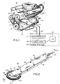
- Appareil pour déterminer les contributions relatives des cylindres individuels à la puissance d'un moteur à combustion interne (10) à cylindres multiples comportant une partie mobile extérieure (15) accessible depuis l'extérieur du moteur et qui se déplace à une vitesse linéaire proportionnelle à la vitesse du moteur, un cycle du moteur étant la période de temps qui sépare les occurences d'allumages consécutifs dans le même cylindre,
ledit appareil comportant : un capteur de vitesse (30), portatif et manoeuvrable manuellement, pour détecter les variations de vitesse linéaire de la partie mobile extérieure du moteur au cours d'un cycle du moteur et pour produire un signal électrique de sortie indicatif de ces variations de vitesse linéaire, des moyens de traitement (21, 60-110) couplés audit capteur de vitesse et répondant audit signal de sortie pour produire un signal en forme d'onde (120) représentant les variations de vitesse linéaire de la partie mobile en fonction du temps, et des moyens d'affichage (25) couplés auxdits moyens de traitement pour afficher un cycle de moteur unique du signal en forme d'onde. - Appareil selon la revendication 1, dans lequel ledit capteur de vitesse est un tachymètre à contact (30).
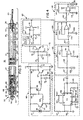
- Appareil selon la revendication 1 ou 2, dans lequel ledit tachymètre comporte un codeur rotatif (50), pouvant être mis en prise avec la partie mobile extérieure et entraîné en rotation par cette dernière pour produire un train d'impulsions dont la fréquence est proportionnelle à la vitesse de la partie mobile.
- Appareil selon la revendication 2 ou 3, dans lequel ledit tachymètre comporte une manette creuse (31) et des moyens (39, 48, 51) pour le montage à rotation dudit codeur rotatif sur ladite manette creuse, ledit appareil comportant en outre un amplificateur (72) disposé dans ladite manette creuse et couplé audit codeur rotatif pour produire un signal de sortie.
- Appareil selon l'une des revendications 1 à 4, dans lequel lesdits moyens de traitement comportent un convertisseur (85) fréquence-tension, pour produire un signal en forme d'onde, dont la tension est proportionnelle à la fréquence du train d'impulsions de sortie émis par ledit codeur rotatif.
- Appareil selon l'une des revendications 1 à 5, dans lequel ledit moyen d'affichage comporte un oscilloscope, de préférence un oscilloscope à tube à rayons cathodiques.
- Appareil selon l'une des revendications 1 à 6, comportant en outre un analyseur de moteur (20) comprenant lesdits moyens d'affichage et lesdits moyens de traitement.
- Appareil selon l'une des revendications 2 à 7, dans lequel ledit tachymètre comporte une manette (31) en deux parties, ces parties coopérant pour définir un étrier (48) et des moyens (39, 51) qui supportent en rotation ledit codeur rotatif dans ledit étrier.
- Appareil selon la revendication 8, dans lequel ladite manette comporte des moyens (32, 36) qui y définissent une chambre creuse (40), lesdits moyens de traitement comprenant des circuits (60-110) placés dans ladite chambre ménagée dans la manette.
- Procédé pour déterminer les contributions relatives de cylindres individuels à la puissance d'un moteur à combustion interne (10) à cylindres multiples comportant une partie mobile extérieure (45) accessible depuis l'extérieur du moteur et qui se déplace à une vitesse linéaire proportionnelle à la vitesse du moteur, un cycle du moteur étant la période de temps qui sépare l'occurence de l'allumage dans un cylindre de l'occurence de l'allumage du cylindre suivant selon l'ordre d'allumage,
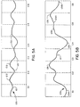
ledit procédé comportant les étapes qui consistent à détecter manuellement la vitesse linéaire de la partie mobile extérieure au cours d'un cycle du moteur au moyen d'un capteur de vitesse portatif (30) pour produire un signal électrique de sortie, à traiter le signal de sortie pour produire un signal (120) en forme d'onde, représentant les variations de la vitesse linéaire de la partie mobile en fonction du temps, à afficher le signal en forme d'onde sous forme graphique dans laquelle la vitesse et le temps sont mesurés respectivement le long d'axes orthogonaux, de telle sorte que les cycles du cylindre occupent sensiblement des distances égales sur l'axe des temps, et à comparer les cycles de cylindre de la forme d'onde au cours d'un cycle unique du moteur. - Procédé selon la revendication 10, dans lequel la vitesse de la partie mobile extérieure est détectée au moyen d'un tachymètre à contact (30).
- Procédé selon la revendication 10 ou 11, dans lequel le signal de sortie est un signal à impulsions dont la fréquence est proportionnelle à la vitesse de la partie mobile extérieure, l'amplitude du signal en forme d'onde étant proportionnelle à la fréquence du signal à impulsions.
- Procédé selon les revendications 10 à 12, dans lequel l'étape d'affichage fournit un affichage en temps réel du signal en forme d'onde.
- Procédé selon les revendications 10 à 13, qui comporte en outre l'étape qui consiste à fournir un signal à chaque occurence d'allumage dans le premier cylindre selon l'ordre d'allumage, pour permettre d'identifier les cylindres dans le signal en forme d'onde.
Applications Claiming Priority (2)
| Application Number | Priority Date | Filing Date | Title |
|---|---|---|---|
| US604191 | 1984-04-26 | ||
| US07/604,191 US5182512A (en) | 1990-10-29 | 1990-10-29 | Method and apparatus for determining relative contributions of individual cylinders of internal combustion engine using contact tachometer |
Publications (3)
| Publication Number | Publication Date |
|---|---|
| EP0483594A2 EP0483594A2 (fr) | 1992-05-06 |
| EP0483594A3 EP0483594A3 (en) | 1993-10-13 |
| EP0483594B1 true EP0483594B1 (fr) | 1996-01-31 |
Family
ID=24418572
Family Applications (1)
| Application Number | Title | Priority Date | Filing Date |
|---|---|---|---|
| EP91117598A Expired - Lifetime EP0483594B1 (fr) | 1990-10-29 | 1991-10-16 | Méthode et appareil pour déterminer les contributions relatives des cylindres individuels des moteurs à combustion interne en utilisant un compteur de vitesse à contact |
Country Status (4)
| Country | Link |
|---|---|
| US (1) | US5182512A (fr) |
| EP (1) | EP0483594B1 (fr) |
| CA (1) | CA2053436C (fr) |
| DE (1) | DE69116797T2 (fr) |
Families Citing this family (8)
| Publication number | Priority date | Publication date | Assignee | Title |
|---|---|---|---|---|
| US5396427A (en) * | 1992-03-09 | 1995-03-07 | Snap-On Incorporated | Method and apparatus for determining relative contributions of individual cylinders of internal combustion engine |
| BR9604203A (pt) * | 1996-10-16 | 1998-05-26 | Sabo Ind & Comercio Ltda | Aperfeiçoamento em vedação |
| US6741925B2 (en) * | 1999-11-02 | 2004-05-25 | Autotronic Controls Corporation | User interface for electronic controller and timing sensor |
| FR2803036B1 (fr) * | 1999-12-23 | 2002-10-11 | Snecma | Detection de l'endommagement de pieces d'un moteur |
| DE10162786B4 (de) * | 2001-12-20 | 2007-08-23 | Abb Patent Gmbh | Verfahren zur Leistungsermittlung, Messvorrichtung und Leistungsprüfstand für einen Prüfling |
| US7230418B2 (en) * | 2004-07-16 | 2007-06-12 | Auto Meter Products, Inc. | Flutter reduction apparatus and method |
| RU2473876C1 (ru) * | 2011-06-08 | 2013-01-27 | ФЕДЕРАЛЬНОЕ ГОСУДАРСТВЕННОЕ ВОЕННОЕ ОБРАЗОВАТЕЛЬНОЕ УЧРЕЖДЕНИЕ ВЫСШЕГО ПРОФЕССИОНАЛЬНОГО ОБРАЗОВАНИЯ "ВОЕННАЯ АКАДЕМИЯ ТЫЛА И ТРАНСПОРТА имени Генерала армии А.В. Хрулева" | Способ диагностирования дизелей на основе анализа временных параметров рабочего цикла |
| CN104678121A (zh) * | 2013-12-03 | 2015-06-03 | 上海华虹宏力半导体制造有限公司 | Apm皮带速度实时监控装置及方法 |
Family Cites Families (38)
| Publication number | Priority date | Publication date | Assignee | Title |
|---|---|---|---|---|
| US3263668A (en) * | 1963-10-08 | 1966-08-02 | Jr Herry L Strauss | Dressing tool for abrasive grinding wheels |
| US3497959A (en) * | 1967-06-09 | 1970-03-03 | Coert Engelsman | Apparatus for making measurements and counting items on maps,drawings,and the like |
| US3601585A (en) * | 1968-09-18 | 1971-08-24 | Dan B Paulsen | Method and apparatus for totalizing materials from construction drawings |
| FR2041011B1 (fr) * | 1969-04-29 | 1974-05-24 | Snecma | |
| US3675199A (en) * | 1970-06-15 | 1972-07-04 | Union Oil Co | Vehicle position marking device |
| US3727033A (en) * | 1971-02-12 | 1973-04-10 | Travis Mills Corp | Yarn measuring apparatus for use with warp knitting machines |
| US3921446A (en) * | 1971-04-07 | 1975-11-25 | Karl Ludloff | Method of measuring torque |
| US3780297A (en) * | 1971-10-04 | 1973-12-18 | Us Industries Inc | Conveyor speed monitor |
| DE2200080A1 (de) * | 1972-01-03 | 1973-07-12 | Siemens Ag | Reibrad-durchmesser-messverfahren und schaltvorrichtung zur ausuebung des verfahrens |
| US3896377A (en) * | 1974-01-02 | 1975-07-22 | Harris Intertype Corp | Printing press instrumentation |
| US4000465A (en) * | 1974-05-04 | 1976-12-28 | Shimpo Kogyo Kabushiki Kaisha | Digital tachometer |
| US3990302A (en) * | 1975-11-26 | 1976-11-09 | Beckman Instruments, Inc. | Automotive ignition analyzer with cylinder of interest display |
| US4061026A (en) * | 1976-05-07 | 1977-12-06 | United Technologies Corporation | Full throttle, specific speed tests in internal combustion engine diagnostics |
| US4064747A (en) * | 1976-05-07 | 1977-12-27 | United Technologies Corporation | Relative and sub-cyclic speed measurements for internal combustion engine diagnostics |
| US4295363A (en) * | 1977-03-25 | 1981-10-20 | Harris Corporation | Apparatus for diagnosing faults in individual cylinders in an internal combustion engine |
| US4179922A (en) * | 1977-03-25 | 1979-12-25 | Harris Corporation | Data acquisition for use in determining malfunctions of cylinders of an internal combustion engine |
| IN149928B (fr) * | 1977-07-22 | 1982-06-05 | Ransome Hoffmann Pollard | |
| US4236449A (en) * | 1979-05-29 | 1980-12-02 | Earl T. Price | Paster pilot sensor for press |
| US4348893A (en) * | 1979-11-13 | 1982-09-14 | United Technologies Corporation | Relative compression of an asymmetric internal combustion engine |
| US4301678A (en) * | 1979-12-20 | 1981-11-24 | United Technologies Corporation | Relative power contribution of an internal combustion engine |
| US4312043A (en) * | 1980-03-21 | 1982-01-19 | Sun Electric Corporation | Apparatus and method for determining the integrity of a distributor for an engine |
| DE3018528C2 (de) * | 1980-05-14 | 1986-06-05 | MTC, Meßtechnik und Optoelektronik AG, Neuenburg/Neuchâtel | Verfahren und Vorrichtung zur Messung der Winkelgeschwindigkeit eines rotierenden Körpers |
| JPS5759138A (en) * | 1980-09-27 | 1982-04-09 | Toyota Motor Corp | Method and device for inspecting engine rough idling |
| JPS5761929A (en) * | 1980-10-01 | 1982-04-14 | Toyota Motor Corp | Measuring method for fluctuation of mean effective pressure of engine shown in diagram |
| US4472881A (en) * | 1981-09-15 | 1984-09-25 | Electronic Modules Corporation | Portable length probe with improved wheel pick-up arrangement |
| DE3145162A1 (de) * | 1981-11-13 | 1983-05-26 | AEG-Kanis Turbinenfabrik GmbH, 8500 Nürnberg | Verfahren zur messung und ueberwachung der drehzahl von schnellaufenden maschinen |
| JPS5952726A (ja) * | 1982-09-20 | 1984-03-27 | Nippon Soken Inc | 内燃機関の出力変動測定方法 |
| JPS60111062A (ja) * | 1983-11-18 | 1985-06-17 | Automob Antipollut & Saf Res Center | 内燃機関の出力バランス診断装置 |
| DE3403358A1 (de) * | 1984-02-01 | 1985-08-01 | Robert Bosch Gmbh, 7000 Stuttgart | Verfahren und vorrichtung zur bestimmung des einflusses unterschiedlicher steuergroessen auf den drehzahlverlauf einer brennkraftmaschine |
| US4539841A (en) * | 1984-02-13 | 1985-09-10 | General Motors Corporation | Method of determining engine cylinder compression pressure and power output |
| US4562728A (en) * | 1984-12-03 | 1986-01-07 | United Technologies Corporation | Absolute compression test |
| US4697561A (en) * | 1985-04-15 | 1987-10-06 | Purdue Research Foundation | On-line engine torque and torque fluctuation measurement for engine control utilizing crankshaft speed fluctuations |
| US4804921A (en) * | 1985-08-23 | 1989-02-14 | Snap-On Tools Corporation | Digital engine analyzer |
| JPS62137454A (ja) * | 1985-12-11 | 1987-06-20 | Toyota Motor Corp | 車速センサの異常判定装置 |
| JPH0726970B2 (ja) * | 1987-02-02 | 1995-03-29 | 株式会社日立製作所 | エンジン回転数検出装置 |
| US4823080A (en) * | 1987-06-26 | 1989-04-18 | Lin Dong Chang | Touchless (photo type) and contact digital dual purpose tachometer |
| US4860585A (en) * | 1988-01-04 | 1989-08-29 | Tuyn William W | Measuring and indicating device for a snow skier |
| US4843870A (en) * | 1988-07-25 | 1989-07-04 | Purdue Research Foundation | Cylinder-by-cylinder engine pressure and pressure torque waveform determination utilizing crankshaft speed fluctuations |
-
1990
- 1990-10-29 US US07/604,191 patent/US5182512A/en not_active Expired - Lifetime
-
1991
- 1991-10-15 CA CA002053436A patent/CA2053436C/fr not_active Expired - Fee Related
- 1991-10-16 EP EP91117598A patent/EP0483594B1/fr not_active Expired - Lifetime
- 1991-10-16 DE DE69116797T patent/DE69116797T2/de not_active Expired - Fee Related
Also Published As
| Publication number | Publication date |
|---|---|
| DE69116797D1 (de) | 1996-03-14 |
| CA2053436A1 (fr) | 1992-04-30 |
| DE69116797T2 (de) | 1996-05-30 |
| EP0483594A2 (fr) | 1992-05-06 |
| EP0483594A3 (en) | 1993-10-13 |
| CA2053436C (fr) | 1999-07-27 |
| US5182512A (en) | 1993-01-26 |
Similar Documents
| Publication | Publication Date | Title |
|---|---|---|
| EP0396665B1 (fr) | Appareil de mesure de puissance | |
| US5646340A (en) | Analytical tachometers | |
| US6396277B1 (en) | Coil on plug signal detection | |
| US4638155A (en) | Optoelectronic measuring device | |
| EP0483594B1 (fr) | Méthode et appareil pour déterminer les contributions relatives des cylindres individuels des moteurs à combustion interne en utilisant un compteur de vitesse à contact | |
| US4578755A (en) | Microprocessor controlled timing/tachometer apparatus | |
| US4263578A (en) | Belt drive connection malfunction sensor | |
| JPH08226930A (ja) | 電気リプルに基づき且つ機械的エンジン信号により校正するタコメータ | |
| US3955135A (en) | Vehicle rpm and dwell measurement system | |
| CA1072211A (fr) | Systeme de mesure des apports dynamiques pour moteurs a combustion interne | |
| US4643023A (en) | Vibration testing apparatus | |
| US4109517A (en) | Method and apparatus for controlling the correct angular adjustment of periodic injection operations | |
| US5004984A (en) | Magnetic field pickup assembly for diagnositics on specific engine | |
| US4783991A (en) | Ignition and combustion engine performance monitor | |
| US4185494A (en) | Diagnostic system for fuel injected engines | |
| US3961239A (en) | Signal conditioning circuit for vehicle diagnostic system | |
| CS196018B1 (en) | Facility for complex diagnosis of ingnition engines | |
| KR100582274B1 (ko) | 차량용 멀티 테스트 장치 | |
| US4517833A (en) | Inductive adaptor/generator for diesel engines | |
| US4423624A (en) | Diesel timing light | |
| US5250896A (en) | Hand-held magnetic contact tachometer with toothed rotatable wheel | |
| US6664789B2 (en) | Engine ignition timing device | |
| US4506546A (en) | Adapter for converting luminosity signals into inductive signals | |
| US4173896A (en) | Device for measuring rotational speed of a diesel engine | |
| CA2162979A1 (fr) | Appareil a accelerometre et methode permettant de determiner la repartition intercylindre de la puissance delivree |
Legal Events
| Date | Code | Title | Description |
|---|---|---|---|
| PUAI | Public reference made under article 153(3) epc to a published international application that has entered the european phase |
Free format text: ORIGINAL CODE: 0009012 |
|
| AK | Designated contracting states |
Kind code of ref document: A2 Designated state(s): DE FR GB IT |
|
| PUAL | Search report despatched |
Free format text: ORIGINAL CODE: 0009013 |
|
| AK | Designated contracting states |
Kind code of ref document: A3 Designated state(s): DE FR GB IT |
|
| 17P | Request for examination filed |
Effective date: 19940302 |
|
| 17Q | First examination report despatched |
Effective date: 19940916 |
|
| GRAA | (expected) grant |
Free format text: ORIGINAL CODE: 0009210 |
|
| AK | Designated contracting states |
Kind code of ref document: B1 Designated state(s): DE FR GB IT |
|
| PG25 | Lapsed in a contracting state [announced via postgrant information from national office to epo] |
Ref country code: IT Free format text: LAPSE BECAUSE OF FAILURE TO SUBMIT A TRANSLATION OF THE DESCRIPTION OR TO PAY THE FEE WITHIN THE PRE;WARNING: LAPSES OF ITALIAN PATENTS WITH EFFECTIVE DATE BEFORE 2007 MAY HAVE OCCURRED AT ANY TIME BEFORE 2007. THE CORRECT EFFECTIVE DATE MAY BE DIFFERENT FROM THE ONE RECORDED.SCRIBED TIME-LIMIT Effective date: 19960131 Ref country code: FR Effective date: 19960131 |
|
| REF | Corresponds to: |
Ref document number: 69116797 Country of ref document: DE Date of ref document: 19960314 |
|
| EN | Fr: translation not filed | ||
| PLBE | No opposition filed within time limit |
Free format text: ORIGINAL CODE: 0009261 |
|
| STAA | Information on the status of an ep patent application or granted ep patent |
Free format text: STATUS: NO OPPOSITION FILED WITHIN TIME LIMIT |
|
| 26N | No opposition filed | ||
| REG | Reference to a national code |
Ref country code: GB Ref legal event code: IF02 |
|
| PGFP | Annual fee paid to national office [announced via postgrant information from national office to epo] |
Ref country code: GB Payment date: 20051013 Year of fee payment: 15 |
|
| PGFP | Annual fee paid to national office [announced via postgrant information from national office to epo] |
Ref country code: DE Payment date: 20051130 Year of fee payment: 15 |
|
| PG25 | Lapsed in a contracting state [announced via postgrant information from national office to epo] |
Ref country code: DE Free format text: LAPSE BECAUSE OF NON-PAYMENT OF DUE FEES Effective date: 20070501 |
|
| GBPC | Gb: european patent ceased through non-payment of renewal fee |
Effective date: 20061016 |
|
| PG25 | Lapsed in a contracting state [announced via postgrant information from national office to epo] |
Ref country code: GB Free format text: LAPSE BECAUSE OF NON-PAYMENT OF DUE FEES Effective date: 20061016 |