EP0483586B1 - Parabole reflector antenna - Google Patents
Parabole reflector antenna Download PDFInfo
- Publication number
- EP0483586B1 EP0483586B1 EP91117534A EP91117534A EP0483586B1 EP 0483586 B1 EP0483586 B1 EP 0483586B1 EP 91117534 A EP91117534 A EP 91117534A EP 91117534 A EP91117534 A EP 91117534A EP 0483586 B1 EP0483586 B1 EP 0483586B1
- Authority
- EP
- European Patent Office
- Prior art keywords
- reflector
- exciter
- antenna
- waveguide
- same
- Prior art date
- Legal status (The legal status is an assumption and is not a legal conclusion. Google has not performed a legal analysis and makes no representation as to the accuracy of the status listed.)
- Expired - Lifetime
Links
Images
Classifications
-
- H—ELECTRICITY
- H01—ELECTRIC ELEMENTS
- H01Q—ANTENNAS, i.e. RADIO AERIALS
- H01Q19/00—Combinations of primary active antenna elements and units with secondary devices, e.g. with quasi-optical devices, for giving the antenna a desired directional characteristic
- H01Q19/10—Combinations of primary active antenna elements and units with secondary devices, e.g. with quasi-optical devices, for giving the antenna a desired directional characteristic using reflecting surfaces
- H01Q19/12—Combinations of primary active antenna elements and units with secondary devices, e.g. with quasi-optical devices, for giving the antenna a desired directional characteristic using reflecting surfaces wherein the surfaces are concave
- H01Q19/13—Combinations of primary active antenna elements and units with secondary devices, e.g. with quasi-optical devices, for giving the antenna a desired directional characteristic using reflecting surfaces wherein the surfaces are concave the primary radiating source being a single radiating element, e.g. a dipole, a slot, a waveguide termination
Landscapes
- Aerials With Secondary Devices (AREA)
Description
Die Erfindung bezieht sich auf eine Antenne mit einem parabolischen Reflektor und einem zur Ausleuchtung desselben dienenden rohrförmigen Erreger, an den mindestens ein denselben tragender Hohlleiter zur Führung elektromagnetischer Wellen angeschlossen ist, bei welcher an der dem Erreger abgewandten Rückseite des Reflektors eine mechanisch stabile Halterung zu seiner Festlegung an einem Träger angebracht ist (DE-C2-3 241 890).The invention relates to an antenna with a parabolic reflector and a tubular exciter for illuminating the same, to which at least one waveguide carrying the same is connected for guiding electromagnetic waves, in which a mechanically stable holder on its side facing away from the exciter Fixing is attached to a carrier (DE-C2-3 241 890).
Antennen mit parabolischem Reflektor werden beispielsweise für Richtfunk oder Satellitenfunk verwendet. Sie können dabei zur direkten Ausleuchtung des Reflektors oder auch zur Ausleuchtung desselben über einen Subreflektor (Cassegrainprinzip) eingesetzt werden. ''Ausleuchtung'' soll dabei beide Übertragungsrichtungen der elektromagnetischen Wellen umfassen, also sowohl abzustrahlende als auch zu empfangene Wellen. Zur Ausleuchtung werden beispielsweise rohrförmige Erreger verwendet, die am freien Ende einer Speiseleitung angeordnet sind.Antennas with a parabolic reflector are used, for example, for directional radio or satellite radio. They can be used to illuminate the reflector directly or to illuminate it using a subreflector (Cassegrain principle). "Illumination" is intended to encompass both directions of transmission of the electromagnetic waves, that is to say both waves to be emitted and waves to be received. For example, tubular exciters are used for the illumination, which are arranged at the free end of a feed line.
Bei der Antenne nach der eingangs erwähnten DE-C2-3 241 890 besteht die Speiseleitung aus zwei rechteckigen Hohlleitern, die an ihren dem Erreger abgewandten Enden mittels einer Halteplatte zentral im Reflektor befestigt sind. Die Speiseleitung und der Erreger haben zusammen ein nicht unerhebliches Gewicht, so daß die Halteplatte sehr stabil ausgeführt und sehr fest im Reflektor gehalten werden muß, damit die vorgegebene Position des Erregers eingehalten werden kann. Zur Sicherung dieser Position werden in den meisten Fällen am Erreger zusätzliche Spannelemente angebracht, die am Rand des Reflektors festgelegt sind. Da außerdem die aus den beiden Hohlleitern bestehende Speiseleitung genau geformt werden muß, ergibt sich insgesamt ein erheblicher Aufwand bei der Herstellung einer kompletten Antenne.In the antenna according to DE-C2-3 241 890 mentioned at the beginning, the feed line consists of two rectangular waveguides which are fastened centrally in the reflector at their ends facing away from the exciter by means of a holding plate. The feed line and the exciter together have a considerable weight, so that the holding plate is very stable and very must be held firmly in the reflector so that the specified position of the pathogen can be maintained. To secure this position, in most cases additional clamping elements are attached to the exciter, which are fixed on the edge of the reflector. In addition, since the feed line consisting of the two waveguides has to be shaped exactly, there is overall a considerable outlay in the production of a complete antenna.
Aus der US-A-2 605 414 ist außerdem eine um einen Drehpunkt frei drehbare Antenne bekannt. Der Reflektor besteht aus einem Teil eines Paraboloids. Er ist einstückig mit einer am Drehpunkt befestigten Halterung verbunden. Die Halterung trägt außerdem einen in Form eines Schwanenhalses gebogenen rechteckigen Hohlleiter, an dessen Ende ein ebenfalls rechteckiger Hohlleiter als Erreger der Antenne angebracht ist.From US-A-2 605 414 an antenna which is freely rotatable about a pivot point is also known. The reflector consists of part of a paraboloid. It is connected in one piece to a bracket attached to the fulcrum. The holder also carries a rectangular waveguide bent in the shape of a gooseneck, at the end of which a likewise rectangular waveguide is attached as the exciter of the antenna.
Eine Halterung für eine Antenne mit parabolischem Reflektor geht aus der DE-A-3 530 809 hervor. Die Halterung dient gleichzeitig zur Verstellung der Antenne. In einer Aufnahme am Rande des Reflektors ist ein Tragerohr befestigt, das an seinem freien Ende ein Bauteil trägt, in dem ein Erreger und ein Konverter zusammengefaßt sind.A holder for an antenna with a parabolic reflector can be found in DE-A-3 530 809. The bracket also serves to adjust the antenna. In a receptacle on the edge of the reflector, a support tube is attached, which carries at its free end a component in which an exciter and a converter are combined.
Der Erfindung liegt die Aufgabe zugrunde, die eingangs geschilderte Antenne so zu gestalten, daß ihr Aufbau einschließlich der Halterung des Erregers wesentlich vereinfacht wird.The invention has for its object to design the antenna described above so that its structure, including the mounting of the exciter is significantly simplified.
Diese Aufgabe wird gemäß der Erfindung dadurch gelöst,
- daß die Halterung eine einteilig mit derselben verbundene, radial über den Rand des Reflektors hinausragende Erweiterung mit einem Tragarm aufweist, der in Richtung der Vorderseite des Reflektors abgebogen ist und parallel zu dessen Achse verlaufend nach vorn über denselben hinausragt und
- daß der den Erreger tragende, geradlinig ausgebildete Hohlleiter an dem Tragarm befestigt ist.
- that the bracket has a one-piece connected to it, radially projecting beyond the edge of the reflector extension with a support arm in the direction of the front of the Reflector is bent and extends parallel to its axis to the front and over it
- that the exciter carrying, straight waveguide is attached to the support arm.
Bei dieser Antenne wird die ohnehin vorhandene, der Befestigung des Reflektors an einem Mast dienende und denselben stabilisierende Halterung gleichzeitig zur Festlegung des den Erreger tragenden Hohlleiters ausgenutzt. Dazu muß die Halterung nur an einer Stelle bis über den Rand des Reflektors erweitert und mit dem Tragarm versehen werden. Der Erreger selbst wird weiter von dem Hohlleiter getragen, der besonders einfach am Tragarm festgelegt werden kann. Es ist dafür keine besondere Formgebung für den Hohlleiter erforderlich, der vielmehr geradlinig verläuft. Da die Halterung des Erregers auf diese Weise außen um den Reflektor herumgeführt ist, kann derselbe ebenfalls einfacher gestaltet werden. Es ist insbesondere im Reflektor keine zentrale Öffnung zur Aufnahme einer Halteplatte mehr erforderlich.In this antenna, the already existing, the fastening of the reflector to a mast and the same stabilizing bracket is used simultaneously to fix the waveguide carrying the exciter. To do this, the bracket only has to be extended in one place to over the edge of the reflector and provided with the support arm. The exciter itself is carried further by the waveguide, which can be attached to the support arm in a particularly simple manner. No special shaping is required for the waveguide, which rather runs in a straight line. Since the holder of the exciter is guided around the outside of the reflector in this way, it can also be made simpler. In the reflector, in particular, a central opening for receiving a holding plate is no longer required.
Ein Ausführungsbeispiel des Erfindungsgegenstandes ist in den Zeichnungen dargestellt.An embodiment of the subject of the invention is shown in the drawings.
Es zeigen:Show it:
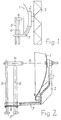
Fig. 1 in schematischer Darstellung eine Antenne nach der Erfindung.Fig. 1 shows a schematic representation of an antenna according to the invention.
Fig. 2 einen Ausschnitt der Antenne in vergrößerter Darstellung.Fig. 2 shows a detail of the antenna in an enlarged view.
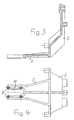
Fig. 3 und 4 ein Einzelteil der Antenne ebenfalls in vergrößerter Darstellung.3 and 4 an individual part of the antenna also in an enlarged view.
In den Zeichnungen ist eine Antenne zur Übertragung von zwei linear polarisierten, senkrecht aufeinander stehenden Wellen dargestellt. An den Erreger sind daher zwei Hohlleiter angeschlossen. Die Anordnung nach der Erfindung ist auch dann anwendbar, wenn nur eine Welle oder mehr als zwei Wellen übertragen werden sollen. An den Erreger sind dann nur ein Hohlleiter oder mehr als zwei Hohlleiter angeschlossen, die den Erreger tragen.An antenna for transmitting two linearly polarized waves perpendicular to one another is shown in the drawings. Two waveguides are therefore connected to the exciter. The arrangement according to the invention can also be used if only one shaft or more than two waves are to be transmitted. Then only one waveguide or more than two waveguides are connected to the exciter, which carry the exciter.
Aus der schematischen Darstellung in Fig. 1 geht ein parabolischer Reflektor 1 einer Antenne hervor, der über eine Halterung 2 an einem Mast 3 befestigt ist. Der Reflektor 1 wird durch einen rohrförmigen Erreger 4 ausgeleuchtet, an den zwei Hohlleiter 5 und 6 angeschlossen sind, die den Erreger 4 in seiner Position halten. In dieser Position liegt die dem Reflektor 1 zugewandte Öffnung des Erregers 4 in dessen Brennpunkt. Die Hohlleiter 5 und 6 sind an einem Tragarm 7 festgelegt, der einstückig mit der Halterung 2 verbunden ist. Der Aufbau des Erregers 4 und die Gestaltung der Hohlleiter 5 und 6 sind grundsätzlich bekannt. Sie werden daher hier nicht erläutert.1 shows a
Die Halterung 2 geht in vergrößerter Darstellung aus den Fig. 2 bis 4 hervor. Sie besteht beispielsweise aus Aluminium und kann als Gußteil ausgeführt sein. Die Halterung 2 wird bei der Herstellung der Antenne auf der Rückseite des Reflektors 1 montiert. Sie dient dabei gleichzeitig zur Stabilisierung des Reflektors 1 und zu seiner Befestigung am Mast 3 oder an einem anderen ausreichend festen Träger.The
Die aus Fig. 3 als Einzelteil hervorgehende Halterung 2 ist an einer Stelle des Umfangs des Reflektors 1 in radialer Richtung so erweitert, daß sie bis über den Rand desselben hinausragt, so wie es aus Fig. 2 zu ersehen ist. An dieser Erweiterung der Halterung 2 ist der Tragarm 7 angebracht, der in Richtung der Vorderseite des Reflektors 1 abgebogen ist. Der Tragarm 7 ist parallel zur Achse A des Reflektors 1 angeordnet, in der auch der Erreger 4 liegt.The
Die beiden geradlinig ausgebildeten Hohlleiter 5 und 6 tragen den Erreger 4. Sie sind auch aus elektrischen Gründen fest mit demselben verbunden. Auf der anderen Seite sind die beiden Hohlleiter 5 und 6 am Tragarm 7 festgelegt. Dazu kann eine mit dem Tragarm 7 zu verbindende Platte 8 verwendet werden, die beispielsweise an Stellen 9 mit dem Tragarm 7 verschraubt wird. Die Hohlleiter 5 und 6 können in einer Vorfertigung an der Platte 8 festgelegt sein.The two
Zur einfachen Anbringung der beiden Hohlleiter 5 und 6 am Tragarm 7 kann derselbe entsprechend Fig. 4 an seinem freien Ende gabelförmig ausgebildet sein, so daß sich eine einseitig offene Ausnehmung 10 ergibt. Die beiden Hohlleiter 5 und 6 lassen sich dann zusammen mit der Platte 8 von der offenen Seite der Ausnehmung 10 her in dieselbe einschieben. In der Endposition wird die Platte 8 mit dem Tragarm 7 verschraubt.For simple attachment of the two
Die Hohlleiter 5 und 6 können an ihren freien Enden mit Flanschen 11 abgeschlossen sein, an die weiterführende Hohlleiter angeschlossen werden können.The
Claims (2)
- Antenna having a parabolic reflector (1) and a tubular exciter (4) used to illuminate the same, to which exciter is connected at least one waveguide (5, 6), carrying the said exciter and for guiding electromagnetic waves, in which antenna, on the rear side, facing away from the exciter (4), of the reflector (1), a mechanically stable holder (2) is attached for fixing the reflector to a carrier (3), characterized- in that the holder (2) has an extension integrally connected to the same, projecting radially beyond the edge of the reflector (1) and having a carrying arm (7) which is bent over in the direction of the front side of the reflector (1) and, extending parallel to the reflector axis (A), projects forwards beyond the same, and- in that the linearly designed waveguide (5, 6) carrying the exciter (4) is fastened to the carrying arm (7).
- Antenna according to Claim 1, characterized in that the carrying arm (7) is configured in the shape of a fork at its free end, to receive the waveguide (5, 6).
Applications Claiming Priority (2)
| Application Number | Priority Date | Filing Date | Title |
|---|---|---|---|
| DE9014875U DE9014875U1 (en) | 1990-10-27 | 1990-10-27 | |
| DE9014875U | 1990-10-27 |
Publications (2)
| Publication Number | Publication Date |
|---|---|
| EP0483586A1 EP0483586A1 (en) | 1992-05-06 |
| EP0483586B1 true EP0483586B1 (en) | 1995-08-16 |
Family
ID=6858808
Family Applications (1)
| Application Number | Title | Priority Date | Filing Date |
|---|---|---|---|
| EP91117534A Expired - Lifetime EP0483586B1 (en) | 1990-10-27 | 1991-10-15 | Parabole reflector antenna |
Country Status (3)
| Country | Link |
|---|---|
| US (1) | US5351061A (en) |
| EP (1) | EP0483586B1 (en) |
| DE (2) | DE9014875U1 (en) |
Citations (1)
| Publication number | Priority date | Publication date | Assignee | Title |
|---|---|---|---|---|
| DE3241890A1 (en) * | 1982-11-12 | 1984-05-17 | kabelmetal electro GmbH, 3000 Hannover | POLARIZING SWITCH WITH FINE HORN |
Family Cites Families (12)
| Publication number | Priority date | Publication date | Assignee | Title |
|---|---|---|---|---|
| US2605414A (en) * | 1945-06-13 | 1952-07-29 | Keary Thomas Joseph | Fan beam radiator |
| US2808586A (en) * | 1953-11-27 | 1957-10-01 | Hughes Aircraft Co | Arrangement for controlling edge diffraction of microwaves |
| NL6704219A (en) * | 1967-03-22 | 1968-09-23 | ||
| CH493110A (en) * | 1968-12-07 | 1970-06-30 | Telefunken Patent | Directional antenna |
| DE1962436C1 (en) * | 1969-12-12 | 1984-05-24 | Siemens AG, 1000 Berlin und 8000 München | Doppler navigation radar antenna with automatic land-sea error correction due to differently inclined groups of lobes |
| CA890032A (en) * | 1970-08-10 | 1972-01-04 | Wu Chuang-Jy | Microwave horn-paraboloidal antenna |
| DE2719283C2 (en) * | 1977-04-29 | 1984-02-02 | Siemens AG, 1000 Berlin und 8000 München | Antenna feed system for double polarization |
| FR2472284A1 (en) * | 1979-12-18 | 1981-06-26 | Aerospatiale | METHOD FOR CORRECTING THE TRANSVERSE DEFOCATION OF A PARABOLOID AND CORRESPONDING DEVICE FOR CORRECTING A PARABOLIC ANTENNA |
| FR2589012B1 (en) * | 1985-06-28 | 1988-06-10 | Hitachi Ltd | PARABOLIC ANTENNA AND MANUFACTURING METHOD THEREOF |
| DE3530809A1 (en) * | 1985-08-29 | 1987-03-05 | Kolbe & Co Hans | Parabolic reflector antenna |
| US4819007A (en) * | 1987-06-22 | 1989-04-04 | Andrew Corporation | Supporting structure for reflector-type microwave antennas |
| DE9001255U1 (en) * | 1990-02-03 | 1990-04-05 | Hagenbusch, Guenther, 7313 Reichenbach, De |
-
1990
- 1990-10-27 DE DE9014875U patent/DE9014875U1/de not_active Expired - Lifetime
-
1991
- 1991-10-15 EP EP91117534A patent/EP0483586B1/en not_active Expired - Lifetime
- 1991-10-15 DE DE59106265T patent/DE59106265D1/en not_active Expired - Fee Related
-
1993
- 1993-07-09 US US08/090,362 patent/US5351061A/en not_active Expired - Fee Related
Patent Citations (1)
| Publication number | Priority date | Publication date | Assignee | Title |
|---|---|---|---|---|
| DE3241890A1 (en) * | 1982-11-12 | 1984-05-17 | kabelmetal electro GmbH, 3000 Hannover | POLARIZING SWITCH WITH FINE HORN |
Also Published As
| Publication number | Publication date |
|---|---|
| EP0483586A1 (en) | 1992-05-06 |
| DE59106265D1 (en) | 1995-09-21 |
| DE9014875U1 (en) | 1991-01-10 |
| US5351061A (en) | 1994-09-27 |
Similar Documents
| Publication | Publication Date | Title |
|---|---|---|
| DE3621532C2 (en) | ||
| DE60113671T2 (en) | High-power and low-cost transceiver satellite antenna | |
| EP1251583A1 (en) | Antenna support | |
| DE69721218T2 (en) | ASSEMBLY OF MICROWAVE TRANSMITTER AND ANTENNA WITH ADJUSTABLE MOUNTING AND ALIGNMENT MECHANISM | |
| DE3822963A1 (en) | MICROWAVE RECEIVER | |
| EP0483586B1 (en) | Parabole reflector antenna | |
| EP1067616A2 (en) | Waveguide twist | |
| DE3530809A1 (en) | Parabolic reflector antenna | |
| DE2618120C2 (en) | Housing for accommodating structural units and devices from radio relay systems | |
| DE19961237A1 (en) | Antenna for radiation and reception of electromagnetic waves | |
| EP0394795B1 (en) | Antenna having a parabolic reflector | |
| DE4307675A1 (en) | Satellite TV receiver for multiple satellites - has fixed dish with feed-horn mounted in such way to allow adjustment to receive signals from one or more nearby satellites. | |
| EP0154619A2 (en) | Holding magnet release | |
| EP0397070B1 (en) | Antenna with a parabolic reflector | |
| DE1766103C3 (en) | Mirror antenna and method for adjusting such | |
| EP0304656B1 (en) | Directional antenna for relay systems | |
| DE4031167C2 (en) | Electric lamp | |
| DE3125593A1 (en) | Antenna holder | |
| EP0947765B1 (en) | Securing device for a recessed light fixture | |
| DE4343125C2 (en) | DF antenna, in particular radar antenna | |
| DE2645700A1 (en) | VHF aerial array with low noise and loss characteristics - has auxiliary reflector on rod frame producing constant lobes | |
| DE3607846C2 (en) | ||
| EP0304722B1 (en) | Directional antenna for relay systems | |
| DE102005012325B4 (en) | Holding device for receiver heads of a satellite antenna | |
| EP0728988A1 (en) | Lamp |
Legal Events
| Date | Code | Title | Description |
|---|---|---|---|
| PUAI | Public reference made under article 153(3) epc to a published international application that has entered the european phase |
Free format text: ORIGINAL CODE: 0009012 |
|
| 17P | Request for examination filed |
Effective date: 19920222 |
|
| AK | Designated contracting states |
Kind code of ref document: A1 Designated state(s): CH DE ES FR GB IT LI NL SE |
|
| 17Q | First examination report despatched |
Effective date: 19940418 |
|
| GRAA | (expected) grant |
Free format text: ORIGINAL CODE: 0009210 |
|
| AK | Designated contracting states |
Kind code of ref document: B1 Designated state(s): CH DE ES FR GB IT LI NL SE |
|
| PG25 | Lapsed in a contracting state [announced via postgrant information from national office to epo] |
Ref country code: IT Free format text: LAPSE BECAUSE OF FAILURE TO SUBMIT A TRANSLATION OF THE DESCRIPTION OR TO PAY THE FEE WITHIN THE PRE;WARNING: LAPSES OF ITALIAN PATENTS WITH EFFECTIVE DATE BEFORE 2007 MAY HAVE OCCURRED AT ANY TIME BEFORE 2007. THE CORRECT EFFECTIVE DATE MAY BE DIFFERENT FROM THE ONE RECORDED.SCRIBED TIME-LIMIT Effective date: 19950816 Ref country code: FR Free format text: THE PATENT HAS BEEN ANNULLED BY A DECISION OF A NATIONAL AUTHORITY Effective date: 19950816 Ref country code: NL Free format text: LAPSE BECAUSE OF NON-PAYMENT OF DUE FEES Effective date: 19950816 Ref country code: ES Free format text: THE PATENT HAS BEEN ANNULLED BY A DECISION OF A NATIONAL AUTHORITY Effective date: 19950816 Ref country code: GB Effective date: 19950816 |
|
| REF | Corresponds to: |
Ref document number: 59106265 Country of ref document: DE Date of ref document: 19950921 |
|
| PG25 | Lapsed in a contracting state [announced via postgrant information from national office to epo] |
Ref country code: LI Effective date: 19951031 Ref country code: CH Effective date: 19951031 |
|
| PG25 | Lapsed in a contracting state [announced via postgrant information from national office to epo] |
Ref country code: SE Effective date: 19951116 |
|
| EN | Fr: translation not filed | ||
| NLV1 | Nl: lapsed or annulled due to failure to fulfill the requirements of art. 29p and 29m of the patents act | ||
| GBV | Gb: ep patent (uk) treated as always having been void in accordance with gb section 77(7)/1977 [no translation filed] |
Effective date: 19950816 |
|
| REG | Reference to a national code |
Ref country code: CH Ref legal event code: PL |
|
| PLBE | No opposition filed within time limit |
Free format text: ORIGINAL CODE: 0009261 |
|
| STAA | Information on the status of an ep patent application or granted ep patent |
Free format text: STATUS: NO OPPOSITION FILED WITHIN TIME LIMIT |
|
| PG25 | Lapsed in a contracting state [announced via postgrant information from national office to epo] |
Ref country code: DE Effective date: 19960801 |
|
| 26N | No opposition filed |