EP0482365A2 - Cut of sheet metal comprising sheet-metal-elements for welding, and laminated core fabricated by such elements - Google Patents
Cut of sheet metal comprising sheet-metal-elements for welding, and laminated core fabricated by such elements Download PDFInfo
- Publication number
- EP0482365A2 EP0482365A2 EP91116185A EP91116185A EP0482365A2 EP 0482365 A2 EP0482365 A2 EP 0482365A2 EP 91116185 A EP91116185 A EP 91116185A EP 91116185 A EP91116185 A EP 91116185A EP 0482365 A2 EP0482365 A2 EP 0482365A2
- Authority
- EP
- European Patent Office
- Prior art keywords
- sheet metal
- sheet
- butt joint
- metal
- welding
- Prior art date
- Legal status (The legal status is an assumption and is not a legal conclusion. Google has not performed a legal analysis and makes no representation as to the accuracy of the status listed.)
- Granted
Links
- 229910052751 metal Inorganic materials 0.000 title claims abstract description 78
- 239000002184 metal Substances 0.000 title claims abstract description 76
- 238000003466 welding Methods 0.000 title claims abstract description 14
- 210000001503 joint Anatomy 0.000 claims abstract description 40
- 230000007423 decrease Effects 0.000 claims description 3
- 238000003475 lamination Methods 0.000 abstract 3
- 239000000463 material Substances 0.000 description 4
- 230000015572 biosynthetic process Effects 0.000 description 2
- 230000000694 effects Effects 0.000 description 2
- 238000004026 adhesive bonding Methods 0.000 description 1
- 238000001816 cooling Methods 0.000 description 1
- 238000010438 heat treatment Methods 0.000 description 1
- 238000004080 punching Methods 0.000 description 1
Images
Classifications
-
- H—ELECTRICITY
- H01—ELECTRIC ELEMENTS
- H01F—MAGNETS; INDUCTANCES; TRANSFORMERS; SELECTION OF MATERIALS FOR THEIR MAGNETIC PROPERTIES
- H01F27/00—Details of transformers or inductances, in general
- H01F27/24—Magnetic cores
- H01F27/245—Magnetic cores made from sheets, e.g. grain-oriented
-
- B—PERFORMING OPERATIONS; TRANSPORTING
- B23—MACHINE TOOLS; METAL-WORKING NOT OTHERWISE PROVIDED FOR
- B23K—SOLDERING OR UNSOLDERING; WELDING; CLADDING OR PLATING BY SOLDERING OR WELDING; CUTTING BY APPLYING HEAT LOCALLY, e.g. FLAME CUTTING; WORKING BY LASER BEAM
- B23K33/00—Specially-profiled edge portions of workpieces for making soldering or welding connections; Filling the seams formed thereby
Definitions
- the invention relates to a sheet metal cut with two sheet metal parts to be welded, the end and side edges of which form two butt joints for close contact, each butt joint ending in a fictitious weld and the two welds on both sides of the areas of close contact.
- the invention also relates to a sheet metal core made from such sheet metal cuts with two welded laminated cores, which are joined together with end faces and side faces to form fictitious contact, each butt joint ending in a weld seam on the outside and the two weld seams lying on both sides of the areas of contact .
- a welded EI sheet metal core in which the I sheet metal stack is assigned with one side face to the end faces of the three legs, the sheet metal packs are pressed together tightly to hold the weld seams and held together.
- the three joints - apart from the areas of the weld seams - are widened into hair gaps, which increase the no-load current and reduce the power in the finished transformer.
- the middle leg can also be opposite the yoke, i.e. the I-laminated core, move what is associated with a humming noise from the transformer.
- the laminated cores can be glued together or it is known (DE-PS 33 18 370) to provide small lugs on the I-laminated core which attack the central leg with deformation. This is cumbersome and, like gluing, does not prevent the increased no-load current or the reduced power.
- the sheet metal cut according to the invention solves this problem, characterized in that the butt joints are widened at each weld to a narrow gap of 0.01-0.06 mm, which extends into the interior of the butt joint by at least one third of the butt joint length.
- the sheet metal core according to the invention solves this problem, characterized in that the weld seam is placed on a narrow gap of 0.01-0.06 mm which widens the butt joint and extends into the inside of the butt joint by at least one third of the butt joint length, the The front and side surfaces are pressed against each other at the points of contact under tension.
- the sheet metal core according to the invention which consists of sheet metal cuts according to the invention
- no narrow gaps have formed at the points of contact, but rather a full contact is achieved, so that the middle leg of an EI sheet metal core can no longer vibrate.
- welding reduces the gap width.
- the shrinking welds take up the butt joint areas between them and use them as abutments for leverage.
- the idling current and power are remarkable, for example up to 20% better conditions than for a same sheet metal core without the narrow gaps in the sheet metal cuts.
- the narrow gap becomes larger, e.g. 0.05 mm.
- the widened narrow gap usually extends at least to half the length of the butt joint.
- the narrow gaps are either included in the stamping of the sheet metal parts or subsequently made by grinding.
- the sheet metal cut has only two sheet metal parts, although it is also conceivable to implement the invention on a sheet metal cut with three or more sheet metal parts.
- the sheet metal cut forms at least the two butt joints expanded into narrow gaps and can have one or more additional butt joints.
- the sheet metal cut or the sheet metal core consists of grain-oriented sheet metal.
- the effect of the measure according to the invention namely the reduction in the no-load current, occurs particularly strongly.
- the two narrow gaps each extend with the same width over the entire leg. This can be produced in a simplified manner and brings about an improved fixing of the middle leg, because the shrinkage of the weld seams can improve the pressure at the parting line of the middle leg.
- the narrow gap decreases in width from the greatest width on the outside to the inside.
- This, generally wedge-shaped, formation of the narrow gap is generally provided in the case of two-legged sheet metal cuts and sheet metal cores. Due to the shrinking weld seams, the laminated cores are pressed against each other at the joints of each joint free of narrow gaps and the width of the tapering narrow gaps is reduced.
- each E-sheet metal part 4 has two outer legs 5, which end at parting lines which are formed by a recess in the I-sheet metal part 2, whereas a middle leg 6 with an end edge 7 is abutting against a side edge 8 of the I-sheet metal part 2. Because of the recesses, the butt joint of each outer leg 5 is designed as a narrow gap 9, which is the same width over its length.
- the two laminated cores 1, 3 are pressed together in the region of the weld seams according to the arrows 11, which already leads to a reduction in the width of the deliberately provided narrow gaps 9.
- 2 and 3 illustrate the I-sheet metal part 2 and the E-sheet metal part 4 and the formation of the narrow gaps 9 in a material-saving sheet metal cut, in which two I-sheet metal parts are obtained when punching the windows of two E-sheet metal parts. It is also conceivable to leave the I-sheet metal part free of the recesses and to make the two outer legs shorter by the width of the narrow gap than the middle leg. 1 has three butt joints, the butt joint 12 assigned to the middle leg 6 being associated with close contact between the front and side edges and the two other butt joints being widened to form the narrow gaps 9.
- two E-laminated cores 13, 14 are joined together to form a sheet metal core, the three butt joints, as in the embodiment in accordance with FIG. 1, lying in a straight line and the two narrow gaps 9 and the butt joint 12 with the tight pressure of each other Take up metal sheets between them.
- this sheet metal core the two weld seams 15 or weld points can be seen.
- the narrow gaps 9 run with the same width over the entire width of the butt joint or the outer legs 5.
- an F laminated core 16 and an L laminated core 17 are joined together.
- the middle leg 6 is formed by the F laminated core 17 and, forming the tight butt joint 12, abuts the yoke formed by the L laminated core 16.
- the butt joints assigned to the outer legs are arranged at right angles to one another and assigned to the two yokes and are designed as narrow gaps 18, which have the greatest width on the outside and taper in width across the width of the separating joint to the window. These two parting lines therefore also form areas 19 of close contact and the cooling shrinking weld seam 15 leads to the two laminated cores 16, 17 being increasingly pulled against one another.
- two-legged sheet metal cores are provided, the two separating joints of which are each formed as a narrow gap 18 tapering in width, which forms the area 19 in close contact with the window.
- the narrow gaps 18 lie on both sides of the areas 19 of close contact and the contracting forces of the shrinking weld seams 15 find an abutment on the areas 19 of close contact, so that they act with leverage.
Landscapes
- Engineering & Computer Science (AREA)
- Power Engineering (AREA)
- Mechanical Engineering (AREA)
- Butt Welding And Welding Of Specific Article (AREA)
Abstract
Description
Die Erfindung betrifft einen Blechschnitt mit zwei zu verschweißenden Blechteilen, die mit Stirn- und Seitenkanten zwei Stoßfugen bildend auf dichte Berührung aneinandergelegt sind, wobei jede Stoßfuge nach außen hin in einer fiktiven Schweißstelle endet und die beiden Schweißstellen beiderseits der Bereiche dichter Berührung liegen.
Die Erfindung betrifft auch einen aus solchen Blechschnitten hergestellten Blechkern mit zwei verschweißten Blechpaketen, die mit Stirn- und Seitenflächen zwei Stoßfugen bildend auf fiktive Berührung aneinandergelegt sind, wobei jede Stoßfuge nach außen hin in einer Schweißnaht endet und die beiden Schweißnähte beiderseits der Bereiche der Berührung liegen.The invention relates to a sheet metal cut with two sheet metal parts to be welded, the end and side edges of which form two butt joints for close contact, each butt joint ending in a fictitious weld and the two welds on both sides of the areas of close contact.
The invention also relates to a sheet metal core made from such sheet metal cuts with two welded laminated cores, which are joined together with end faces and side faces to form fictitious contact, each butt joint ending in a weld seam on the outside and the two weld seams lying on both sides of the areas of contact .
Wenn ein geschweißter EI-Blechkern hergestellt wird, bei dem das I-Blechpaket mit einer Seitenfläche den Stirnflächen der drei Schenkel zugeordnet ist, so werden die Blechpakete zum Legen der Schweißnähte dicht aneinandergedrückt und zusammengehalten. Wenn die Schweißnähte gelegt sind, dann sind die drei Trennfugen - abgesehen von den Bereichen der Schweißnähte - zu Haarspalten aufgeweitet, welche beim fertigen Transformator den Leerlaufstrom vergrößern und die Leistung verkleinern. Auch kann sich der Mittelschenkel gegenüber dem Joch, d.h. dem I-Blechpaket, bewegen, was mit einem Brummgeräusch des Transformators verbunden ist. Um dieses Brummgeräusch zu unterbinden, können die Blechpakete miteinander verklebt werden oder ist es bekannt (DE-PS 33 18 370), am I-Blechpaket kleine Nasen vorzusehen, die am Mittelschenkel unter Verformung angreifen. Dies ist umständlich und verhindert ebenso wie das Verkleben den vergrößerten Leerlaufstrom bzw. die verkleinerte Leistung nicht.If a welded EI sheet metal core is produced, in which the I sheet metal stack is assigned with one side face to the end faces of the three legs, the sheet metal packs are pressed together tightly to hold the weld seams and held together. When the weld seams are in place, the three joints - apart from the areas of the weld seams - are widened into hair gaps, which increase the no-load current and reduce the power in the finished transformer. The middle leg can also be opposite the yoke, i.e. the I-laminated core, move what is associated with a humming noise from the transformer. In order to prevent this humming noise, the laminated cores can be glued together or it is known (DE-PS 33 18 370) to provide small lugs on the I-laminated core which attack the central leg with deformation. This is cumbersome and, like gluing, does not prevent the increased no-load current or the reduced power.
Eine Aufgabe der Erfindung ist es daher, einen Blechschnitt und einen Blechkern der eingangs genannten Art zu schaffen, bei dem eine Verbesserung der Leistung bzw. Verkleinerung des Leerlaufstromes eines damit hergestellten Transformators dadurch gegeben ist, daß die beiden Blechteile bzw. Blechpakete nach dem Verschweißen im Berührungsbereich unter Spannung dicht aneinandergedrückt sind.
Der erfindungsgemäße Blechschnitt ist, diese Aufgabe lösend, dadurch gekennzeichnet, daß die Stoßfugen bei jeder Schweißstelle zu einem Engspalt von 0,01 - 0,06 mm aufgeweitet sind, der sich in das Innere der Stoßfuge um mindestens ein Drittel der Stoßfugenlänge erstreckt.
Der erfindungsgemäße Blechkern ist, diese Aufgabe lösend, dadurch gekennzeichnet, daß die Schweißnaht an einen die Stoßfuge aufweitenden Engspalt von 0,01 - 0,06 mm gesetzt ist, der sich in das Innere der Stoßfuge um mindestens ein Drittel der Stoßfugenlänge erstreckt, wobei die Stirn- und Seitenflächen an den Berührungsstellen unter Spannung gegeneinandergedrückt sind.It is therefore an object of the invention to provide a sheet metal cut and a sheet metal core of the type mentioned in the introduction, in which an improvement in performance or reduction of the no-load current of a transformer produced in this way is given in that the two sheet metal parts or sheet packs are pressed tightly together under tension after welding in the contact area.
The sheet metal cut according to the invention solves this problem, characterized in that the butt joints are widened at each weld to a narrow gap of 0.01-0.06 mm, which extends into the interior of the butt joint by at least one third of the butt joint length.
The sheet metal core according to the invention solves this problem, characterized in that the weld seam is placed on a narrow gap of 0.01-0.06 mm which widens the butt joint and extends into the inside of the butt joint by at least one third of the butt joint length, the The front and side surfaces are pressed against each other at the points of contact under tension.
Bei dem erfindungsgemäßen Blechkern, der aus erfindungsgemäßen Blechschnitten besteht, sind an den Berührungsstellen keine Engspalte entstanden, sondern ist eine satte Anlage erreicht, so daß der Mittelschenkel eines EI-Blechkernes nicht mehr schwingen kann. Auch dort, wo die Blechschmitte zunächst die bewußt vorgesehenen Engspalte aufweisen, ist durch das Verschweißen eine Verringerung der Spaltbreite erreicht. Die schrumpfenden Schweißnähte nehmen die Stoßfugen-Bereiche enger Berührung zwischen sich auf und nutzen diese als Widerlager für eine Hebelwirkung. Für einen erfindungsgemäßen Blechkern ergeben sich bezüglich Leerlaufstrom und Leistung beachtlich, z.B. bis zu 20% bessere Verhältnisse als für einen gleichen Blechkern ohne die Engspalte der Blechschnitte. Eine denkbare Erklärung für diese Wirkung der Erfindung besteht in folgendem: Beim Legen der Schweißmähe kann das sich erhitzende Material in die Engspalte ausweichen und drückt die beiden Blechpakete nicht auseinander. Beim Erkalten der Schweißmähte schrumpfen diese und ziehem die Blechpakete aufeinander zu. Bei dreischenkeligen Blechkernen ist ein Brummgeräusch durch den Mittelschenkel vermieden und zwar ohne zusätzliche mechanische Maßnahme. Die Verbesserung der Leerlaufstrom- bzw. Leistungs-Verhältnisse ist unabhängig vom der Schenkelzahl der Blechkerne gegeben.In the sheet metal core according to the invention, which consists of sheet metal cuts according to the invention, no narrow gaps have formed at the points of contact, but rather a full contact is achieved, so that the middle leg of an EI sheet metal core can no longer vibrate. Even where the sheet metal center initially has the deliberately intended narrow gaps, welding reduces the gap width. The shrinking welds take up the butt joint areas between them and use them as abutments for leverage. For a sheet metal core according to the invention, the idling current and power are remarkable, for example up to 20% better conditions than for a same sheet metal core without the narrow gaps in the sheet metal cuts. A conceivable explanation for this effect of the invention is as follows: When the welding mower is placed, the heating material can escape into the narrow gaps and does not press the two laminated cores apart. When the welding seams cool down, they shrink and pull the sheet packs towards each other. With three-legged sheet metal cores, a humming noise through the middle leg is avoided and without additional mechanical Measure. The improvement in the idle current and power ratios is independent of the number of legs of the sheet metal cores.
Bei der erfindungsgemäßen Gestaltung sind Vorsprünge oder Eingriffe an den Stirn- und Seitenkanten bzw. den Stirn- und Seitenflächen vermieden und sind diese insoweit plan bzw. glatt. Auch an Stoßfugen sind vor- und zurückspringende Blechteile, die bei einem bekannten (DE-OS 33 27 239) Blechkern im Zusammenhang mit dem hier behandelten Problem vorgesehen sind, vermieden. Während des Legens der Schweißnähte werden die Blechpakete im Bereich der Schweißnähte gegeneinandergepreßt. Die Schweißnähte brennen sich in das Material ein. Es wird in der Regel ohne Zugabe von Material geschweißt. Die Erfindung ist jedoch auch wirksam, wenn die Schweißnähte unter Zugabe von Material gelegt werden. Bei kleineren Blechschnitten wird der Engspalt kleiner, z.B. 0,02 mm, sein und bei größeren Blechschnitten wir der Engspalt größer, z.B. 0,05 mm, sein. Der aufgeweitete Engspalt erstreckt sich in der Regel mindestens auf die Hälfte der Stoßfugenlänge. Die Engspalte werden entweder gleich beim Stanzen der Blechteile mit vorgesehen oder nachträglich durch Abschleifen hergestellt. In der Regel weist der Blechschnitt nur zwei Blechteile auf, obwohl es auch denkbar ist, die Erfindung an einem Blechschnitt mit drei oder mehr Blechteilen zu verwirklichen. Der Blechschnitt bildet mindestens die zwei zu Engspalten erweiterten Stoßfugem und kann eine oder mehrere weitere Stoßfugen aufweisen.In the design according to the invention, projections or interventions on the front and side edges or the front and side surfaces are avoided and in this respect they are flat or smooth. Also on butt joints protruding and recessed sheet metal parts, which are provided in a known (DE-OS 33 27 239) sheet metal core in connection with the problem dealt with here, are avoided. During the laying of the weld seams, the laminated cores are pressed against each other in the area of the weld seams. The weld seams burn themselves into the material. As a rule, welding is carried out without adding material. However, the invention is also effective when the welds are made with the addition of material. With smaller sheet metal cuts, the narrow gap becomes smaller, e.g. 0.02 mm, and with larger sheet metal cuts the narrow gap becomes larger, e.g. 0.05 mm. The widened narrow gap usually extends at least to half the length of the butt joint. The narrow gaps are either included in the stamping of the sheet metal parts or subsequently made by grinding. As a rule, the sheet metal cut has only two sheet metal parts, although it is also conceivable to implement the invention on a sheet metal cut with three or more sheet metal parts. The sheet metal cut forms at least the two butt joints expanded into narrow gaps and can have one or more additional butt joints.
Besonders zweckmäßig und vorteilhaft ist es, wenn der Blechschnitt oder der Blechkern aus kornorientiertem Blech besteht. Bei kornorientiertem Blech tritt die Wirkung der erfindungsgemäßen Maßnahme, nämlich die Verringerung des Leerlaufstromes, besonders ausgeprägt auf.It is particularly expedient and advantageous if the sheet metal cut or the sheet metal core consists of grain-oriented sheet metal. In the case of grain-oriented sheet metal, the effect of the measure according to the invention, namely the reduction in the no-load current, occurs particularly strongly.
Wenn eine dreischenkelige Ausbildung und die Schweißstellen an den beiden Außenschenkeln vorgesehen sind, ist es besonders zweckmäßig und vorteilhaft, wenn die beiden Engspalten sich jeweils mit gleicher Breite über den gesamten Schenkel erstrecken. Dies läßt sich vereinfacht erzeugen und bewirkt eine verbesserte Festlegung des Mittelschenkels, weil die Schrumpfung der Schweißnähte die Pressung an der Trennfuge des Mittelschenkels verbessern kann.If a three-legged training and the welds are provided on the two outer legs, it is particularly expedient and advantageous if the two narrow gaps each extend with the same width over the entire leg. This can be produced in a simplified manner and brings about an improved fixing of the middle leg, because the shrinkage of the weld seams can improve the pressure at the parting line of the middle leg.
Besonders zweckmäßig und vorteilhaft ist es auch, wenn der Engspalt sich von einer größten Breite an der Außenseite in der Breite nach innen hin vermindert. Diese, in der Regel keilförmige, Ausbildung des Engspaltes wird in der Regel bei zweischenkeligen Blechschnitten und Blechkernen vorgesehen. Durch die schrumpfenden Schweißnähte werden die Blechpakete an den von Engspalt freien Trennfugen-Stellen jeder Trennfuge gegeneinander gepreßt und wird die Breite der sich verjüngenden Engspalte verringert.It is also particularly expedient and advantageous if the narrow gap decreases in width from the greatest width on the outside to the inside. This, generally wedge-shaped, formation of the narrow gap is generally provided in the case of two-legged sheet metal cuts and sheet metal cores. Due to the shrinking weld seams, the laminated cores are pressed against each other at the joints of each joint free of narrow gaps and the width of the tapering narrow gaps is reduced.
In der Zeichnung sind bevorzugte Ausführungsformen der Erfindung dargestellt und zeigt
- Fig. 1
- eine perspektivische Ansicht eines dreischenkeligen Blechkernes vor dem Verschweißen,
- Fig. 2
- ein I-Blechteil eines Blechschnittes des Blechkernes gemäß Fig. 1,
- Fig. 3
- ein E-Blechteil des Blechschnittes zu Fig. 2 des Blechkernes gemäß Fig. 1,
- Fig. 4
- eine Vorderansicht eines zweiten dreischenkeligen Blechkernes im verschweißten Zustand,
- Fig. 5
- eine Vorderansicht eines dritten dreischenkeligen Blechkernes im verschweißten Zustand,
- Fig. 6
- eine Vorderansicht eines zweischenkeligen Blechkernes im verschweißten Zustand und
- Fig. 7
- eine Vorderansicht eines zweiten zweischenkeligen Blechkernes im verschweißten Zustand.
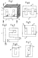
- Fig. 1
- a perspective view of a three-legged sheet metal core before welding,
- Fig. 2
- 1 an I-sheet metal part of a sheet metal section of the sheet metal core according to FIG. 1,
- Fig. 3
- 2 shows an E-sheet metal part of the sheet metal section of FIG. 2 of the sheet metal core according to FIG. 1,
- Fig. 4
- 2 shows a front view of a second three-legged sheet metal core in the welded state,
- Fig. 5
- a front view of a third three-legged sheet metal core in the welded state,
- Fig. 6
- a front view of a two-legged sheet metal core in the welded state and
- Fig. 7
- a front view of a second two-legged sheet metal core in the welded state.
Der Blechkern gemäß Fig. 1 besteht aus einem I-Blechpaket 1, das aus I-Blechteilen 2 geschichtet ist, und aus einem E-Blechpaket 3, das aus E-Blechteilen 4 geschichtet ist. Jedes E-Blechteil 4 weist zwei Außenschenkel 5 auf, die an Trennfugen enden die von einer Ausnehmung im I-Blechteil 2 gebildet sind, wogegen ein Mittelschenkel 6 mit einer Stirnkante 7 dicht anliegend auf eine Seitenkante 8 des I-Blechteiles 2 aufgestoßen ist. Aufgrund der Ausnehmungen ist die Stoßfuge jedes Außenschenkels 5 als Engspalt 9 ausgebildet, der über seine Länge hin gleich breit ist. Zum Legen vom Schweißnähten entlang äußeren Enden 10 der Engspalte 9 werden die beiden Blechpakete 1, 3 gemäß den Pfeilen 11 im Bereich der Schweißnähte zusammengedrückt, was bereits zu einer Verringerung der Breite der bewußt vorgesehenen Engspalte 9 führt. Fig. 2 und 3 verdeutlichen das I-Blechteil 2 und das E-Blechteil 4 und die Bildung der Engspalten 9 bei einem materialsparenden Blechschnitt, bei dem zwei I-Blechteile beim Stanzen der Fenster zweier E-Blechteile anfallen. Es ist auch denkbar, das I-Blechteil frei vom Ausnehmungen zu lassen und die beiden Außenschenkel um die Breite des Engspaltes kürzer zu machen als den Mittelschenkel. Der Blechkern gemäß Fig. 1 weist drei Stoßfugen auf, wobei der dem Mittelschenkel 6 zugeordneten Stoßfuge 12 auf dichte Berührung aneinandergelegte Stirn- und Seitenkanten zugeordnet sind und die beiden anderem Stoßfugen zu den Engspalten 9 aufgeweitet sind.1 consists of an I-
Gemäß Fig. 4 sind zwei E-Blechpakete 13, 14 zu einem Blechkern zusammengefügt, wobei die drei Stoßfugen, wie bei der Ausführungsform gemäß Fig. 1, in einer geraden Linie liegen und die beiden Engspalte 9 und die Stoßfuge 12 mit dem dichten Aneinanderdruck der Blechpakete zwischen sich aufnehmen. Bei diesem Blechkern sind die beiden Schweißnähte 15 bzw. Schweißstellen zu sehen. Auch hier verlaufen die Engspalte 9 mit gleicher Breite über die gesamte Breite der Stoßfuge bzw. der Außenschenkel 5. Gemäß Fig. 5 sind ein F-Blechpaket 16 und ein L-Blechpaket 17 zusammengefügt. Der Mittelschenkel 6 wird vom F-Blechpaket 17 gebildet und stößt, die dichte Stoßfuge 12 bildend, gegen das vom L-Blechpaket 16 gebildete Joch. Die den Außenschenkeln zugeorndeten Stoßfugen sind rechtwinkelig zueinander angeordnet und den beiden Jochen zugeordnet und sind als Engspalte 18 ausgebildet, die an der Außenseite eine größte Breite aufweisen und sich über die Breite der Trennfuge bis zum Fenster in der Breite verjüngen. Auch diese beiden Trennfugen bilden also Bereiche 19 enger Berührung und die erkaltende schrumpfende Schweißnaht 15 führt dazu, daß die beiden Blechpakete 16, 17 verstärkt gegeneinander gezogen werden.4, two
Gemäß Fig. 6 und 7 sind zweischenkelige Blechkerne vorgesehen, deren beiden Trennfugen jeweils als sich in der Breite verjüngender Engspalt 18 ausgebildet sind, der beim Fenster den Bereich 19 enger Berührung bildet. Auch hier liegen die Engspalte 18 beiderseits der Bereiche 19 enger Berührung und finden die zusammenziehenden Kräfte der schrumpfenden Schweißnähte 15 an den Bereichen 19 enger Berührung ein Widerlager, so daß sie mit Hebelwirkung angreifen.According to FIGS. 6 and 7, two-legged sheet metal cores are provided, the two separating joints of which are each formed as a
Claims (8)
Applications Claiming Priority (2)
| Application Number | Priority Date | Filing Date | Title |
|---|---|---|---|
| DE19904033910 DE4033910C1 (en) | 1990-10-25 | 1990-10-25 | |
| DE4033910 | 1990-10-25 |
Publications (3)
| Publication Number | Publication Date |
|---|---|
| EP0482365A2 true EP0482365A2 (en) | 1992-04-29 |
| EP0482365A3 EP0482365A3 (en) | 1993-01-13 |
| EP0482365B1 EP0482365B1 (en) | 1995-11-22 |
Family
ID=6417012
Family Applications (1)
| Application Number | Title | Priority Date | Filing Date |
|---|---|---|---|
| EP19910116185 Expired - Lifetime EP0482365B1 (en) | 1990-10-25 | 1991-09-24 | Cut of sheet metal comprising sheet-metal-elements for welding, and laminated core fabricated by such elements |
Country Status (2)
| Country | Link |
|---|---|
| EP (1) | EP0482365B1 (en) |
| DE (1) | DE4033910C1 (en) |
Citations (3)
| Publication number | Priority date | Publication date | Assignee | Title |
|---|---|---|---|---|
| JPS58106812A (en) * | 1981-12-18 | 1983-06-25 | Tamura Seisakusho Co Ltd | Core unit |
| GB2131626A (en) * | 1982-11-12 | 1984-06-20 | Gen Electric Plc | Variable set core for choke or transformer |
| JPH02138712A (en) * | 1988-11-18 | 1990-05-28 | Matsushita Electric Ind Co Ltd | Transformer |
Family Cites Families (2)
| Publication number | Priority date | Publication date | Assignee | Title |
|---|---|---|---|---|
| DE3318370C2 (en) * | 1983-05-20 | 1986-02-06 | Waasner, Bruno, 8550 Forchheim | Sheet metal core made of two parts and with three legs |
| DE3327239A1 (en) * | 1983-07-28 | 1985-02-07 | Bruno 8550 Forchheim Waasner | Two-piece sheet-metal core with centre-limb fixing |
-
1990
- 1990-10-25 DE DE19904033910 patent/DE4033910C1/de not_active Expired - Fee Related
-
1991
- 1991-09-24 EP EP19910116185 patent/EP0482365B1/en not_active Expired - Lifetime
Patent Citations (3)
| Publication number | Priority date | Publication date | Assignee | Title |
|---|---|---|---|---|
| JPS58106812A (en) * | 1981-12-18 | 1983-06-25 | Tamura Seisakusho Co Ltd | Core unit |
| GB2131626A (en) * | 1982-11-12 | 1984-06-20 | Gen Electric Plc | Variable set core for choke or transformer |
| JPH02138712A (en) * | 1988-11-18 | 1990-05-28 | Matsushita Electric Ind Co Ltd | Transformer |
Non-Patent Citations (2)
| Title |
|---|
| PATENT ABSTRACTS OF JAPAN vol. 14, no. 380 (E-965)(4323) 16. August 1990 & JP-A-02 138 712 ( MATSUSHITA ) 28. Mai 1990 * |
| PATENT ABSTRACTS OF JAPAN vol. 7, no. 214 (E-199)(1359) 21. September 1983 & JP-A-58 106 812 ( TAMURA SEISAKUSHO K.K. ) 25. Juni 1983 * |
Also Published As
| Publication number | Publication date |
|---|---|
| EP0482365B1 (en) | 1995-11-22 |
| EP0482365A3 (en) | 1993-01-13 |
| DE4033910C1 (en) | 1991-09-26 |
Similar Documents
| Publication | Publication Date | Title |
|---|---|---|
| DE69936824T2 (en) | Iron core and method of making the same | |
| DE69527333T2 (en) | cHOKE COIL | |
| DE2851670C2 (en) | Transformer with negative current-voltage characteristic for the power supply of a welding arc | |
| DE69400378T2 (en) | Clamping ring and manufacturing method | |
| DE3511125C2 (en) | ||
| EP0126451B1 (en) | Two-part, three-legged core | |
| DE2723099C2 (en) | Laminated iron core for electrical machines, such as transformers or the like. | |
| DE1613628A1 (en) | Two-part iron core, especially for transformers | |
| DE2526502A1 (en) | MAGNETIC CORE FOR 3-PHASE TRANSFORMERS | |
| DE2920365C2 (en) | ||
| DE2658665C2 (en) | Core sheet for a shell core | |
| EP0482365B1 (en) | Cut of sheet metal comprising sheet-metal-elements for welding, and laminated core fabricated by such elements | |
| DE2521666A1 (en) | STAR-SHAPED CORE ELEMENT FOR MAGNETIC FLOW FORMATION, PROCESS FOR ITS MANUFACTURING AND TRANSFORMER MANUFACTURED FROM IT | |
| DE2654489C3 (en) | Three-limb core for a single-phase transformer | |
| DE2838697A1 (en) | TRANSFORMER AND PROCESS FOR ITS MANUFACTURING | |
| CH647089A5 (en) | METHOD FOR PRODUCING VOLTAGE-DEPENDENT NON-LINEAR RESISTORS. | |
| DE3005567C2 (en) | ||
| DE3402036C1 (en) | Method for producing E-shaped core laminates and I-shaped magnetic return path laminates of an inductor or of a transformer, especially for gas-discharge lamps | |
| DE2650074A1 (en) | CORE SHEET FOR SHELL, IN PARTICULAR FOR TRANSFORMERS | |
| DE2702455A1 (en) | Three=phase transformer core - has three rectangular rings with parallel sides adjacent, to form triangular prism shape | |
| DE2923069A1 (en) | MAGNETIC CORE FOR ELECTROMAGNETIC DEVICES | |
| DE2753709A1 (en) | PACKAGE TO BE MADE OF SHEET METAL FOR ELECTRICAL MACHINERY, SUCH AS TRANSFORMERS, REACTOR COILS, IGNITION COILS, ELECTRIC MOTORS, GENERATORS OR THE LIKE. | |
| DE9017656U1 (en) | Sheet metal cuts with sheet metal parts to be welded | |
| DE2755218A1 (en) | CORE SHEET FOR SHELL, IN PARTICULAR FOR TRANSFORMERS | |
| DE2252165C3 (en) | Layered core for transformers or reactors with high performance |
Legal Events
| Date | Code | Title | Description |
|---|---|---|---|
| PUAI | Public reference made under article 153(3) epc to a published international application that has entered the european phase |
Free format text: ORIGINAL CODE: 0009012 |
|
| AK | Designated contracting states |
Kind code of ref document: A2 Designated state(s): AT BE CH DE DK ES FR GB GR IT LI LU NL SE |
|
| RBV | Designated contracting states (corrected) |
Designated state(s): CH FR GB IT LI |
|
| REG | Reference to a national code |
Ref country code: DE Ref legal event code: 8566 |
|
| PUAL | Search report despatched |
Free format text: ORIGINAL CODE: 0009013 |
|
| AK | Designated contracting states |
Kind code of ref document: A3 Designated state(s): AT BE CH DE DK ES FR GB GR IT LI LU NL SE |
|
| 17P | Request for examination filed |
Effective date: 19930713 |
|
| 17Q | First examination report despatched |
Effective date: 19940413 |
|
| GRAA | (expected) grant |
Free format text: ORIGINAL CODE: 0009210 |
|
| AK | Designated contracting states |
Kind code of ref document: B1 Designated state(s): CH FR GB IT LI |
|
| GBT | Gb: translation of ep patent filed (gb section 77(6)(a)/1977) |
Effective date: 19951117 |
|
| REG | Reference to a national code |
Ref country code: CH Ref legal event code: NV Representative=s name: E. BLUM & CO. PATENTANWAELTE |
|
| ITF | It: translation for a ep patent filed | ||
| ET | Fr: translation filed | ||
| PLBE | No opposition filed within time limit |
Free format text: ORIGINAL CODE: 0009261 |
|
| STAA | Information on the status of an ep patent application or granted ep patent |
Free format text: STATUS: NO OPPOSITION FILED WITHIN TIME LIMIT |
|
| 26N | No opposition filed | ||
| REG | Reference to a national code |
Ref country code: GB Ref legal event code: IF02 |
|
| PGFP | Annual fee paid to national office [announced via postgrant information from national office to epo] |
Ref country code: GB Payment date: 20040914 Year of fee payment: 14 |
|
| PGFP | Annual fee paid to national office [announced via postgrant information from national office to epo] |
Ref country code: FR Payment date: 20040917 Year of fee payment: 14 |
|
| PGFP | Annual fee paid to national office [announced via postgrant information from national office to epo] |
Ref country code: CH Payment date: 20040923 Year of fee payment: 14 |
|
| PG25 | Lapsed in a contracting state [announced via postgrant information from national office to epo] |
Ref country code: IT Free format text: LAPSE BECAUSE OF NON-PAYMENT OF DUE FEES;WARNING: LAPSES OF ITALIAN PATENTS WITH EFFECTIVE DATE BEFORE 2007 MAY HAVE OCCURRED AT ANY TIME BEFORE 2007. THE CORRECT EFFECTIVE DATE MAY BE DIFFERENT FROM THE ONE RECORDED. Effective date: 20050924 Ref country code: GB Free format text: LAPSE BECAUSE OF NON-PAYMENT OF DUE FEES Effective date: 20050924 |
|
| PG25 | Lapsed in a contracting state [announced via postgrant information from national office to epo] |
Ref country code: CH Free format text: LAPSE BECAUSE OF NON-PAYMENT OF DUE FEES Effective date: 20050930 Ref country code: LI Free format text: LAPSE BECAUSE OF NON-PAYMENT OF DUE FEES Effective date: 20050930 |
|
| REG | Reference to a national code |
Ref country code: CH Ref legal event code: PL |
|
| GBPC | Gb: european patent ceased through non-payment of renewal fee |
Effective date: 20050924 |
|
| PG25 | Lapsed in a contracting state [announced via postgrant information from national office to epo] |
Ref country code: FR Free format text: LAPSE BECAUSE OF NON-PAYMENT OF DUE FEES Effective date: 20060531 |
|
| REG | Reference to a national code |
Ref country code: FR Ref legal event code: ST Effective date: 20060531 |