EP0482258B1 - Cathode stripping apparatus - Google Patents
Cathode stripping apparatus Download PDFInfo
- Publication number
- EP0482258B1 EP0482258B1 EP90311692A EP90311692A EP0482258B1 EP 0482258 B1 EP0482258 B1 EP 0482258B1 EP 90311692 A EP90311692 A EP 90311692A EP 90311692 A EP90311692 A EP 90311692A EP 0482258 B1 EP0482258 B1 EP 0482258B1
- Authority
- EP
- European Patent Office
- Prior art keywords
- cathode
- sheets
- station
- carousel
- cathodes
- Prior art date
- Legal status (The legal status is an assumption and is not a legal conclusion. Google has not performed a legal analysis and makes no representation as to the accuracy of the status listed.)
- Expired - Lifetime
Links
- 229910052751 metal Inorganic materials 0.000 claims description 28
- 239000002184 metal Substances 0.000 claims description 28
- 238000000926 separation method Methods 0.000 claims description 13
- 238000000034 method Methods 0.000 claims description 12
- 238000007599 discharging Methods 0.000 claims description 7
- 230000005484 gravity Effects 0.000 claims description 3
- RYGMFSIKBFXOCR-UHFFFAOYSA-N Copper Chemical compound [Cu] RYGMFSIKBFXOCR-UHFFFAOYSA-N 0.000 description 6
- 229910052802 copper Inorganic materials 0.000 description 6
- 239000010949 copper Substances 0.000 description 6
- 229910000831 Steel Inorganic materials 0.000 description 4
- 230000007246 mechanism Effects 0.000 description 4
- 239000010959 steel Substances 0.000 description 4
- HCHKCACWOHOZIP-UHFFFAOYSA-N Zinc Chemical compound [Zn] HCHKCACWOHOZIP-UHFFFAOYSA-N 0.000 description 3
- 229910001220 stainless steel Inorganic materials 0.000 description 3
- 239000010935 stainless steel Substances 0.000 description 3
- 229910052725 zinc Inorganic materials 0.000 description 3
- 239000011701 zinc Substances 0.000 description 3
- PXHVJJICTQNCMI-UHFFFAOYSA-N Nickel Chemical compound [Ni] PXHVJJICTQNCMI-UHFFFAOYSA-N 0.000 description 2
- 230000000712 assembly Effects 0.000 description 2
- 238000000429 assembly Methods 0.000 description 2
- 238000010276 construction Methods 0.000 description 2
- 238000003780 insertion Methods 0.000 description 2
- 230000037431 insertion Effects 0.000 description 2
- 238000007689 inspection Methods 0.000 description 2
- 239000011800 void material Substances 0.000 description 2
- 238000005303 weighing Methods 0.000 description 2
- -1 Polyethylene Polymers 0.000 description 1
- 239000004698 Polyethylene Substances 0.000 description 1
- 206010042618 Surgical procedure repeated Diseases 0.000 description 1
- 238000009825 accumulation Methods 0.000 description 1
- 230000009471 action Effects 0.000 description 1
- 239000004411 aluminium Substances 0.000 description 1
- 229910052782 aluminium Inorganic materials 0.000 description 1
- XAGFODPZIPBFFR-UHFFFAOYSA-N aluminium Chemical compound [Al] XAGFODPZIPBFFR-UHFFFAOYSA-N 0.000 description 1
- 238000005452 bending Methods 0.000 description 1
- 229910017052 cobalt Inorganic materials 0.000 description 1
- 239000010941 cobalt Substances 0.000 description 1
- GUTLYIVDDKVIGB-UHFFFAOYSA-N cobalt atom Chemical compound [Co] GUTLYIVDDKVIGB-UHFFFAOYSA-N 0.000 description 1
- 230000007547 defect Effects 0.000 description 1
- 239000012530 fluid Substances 0.000 description 1
- 238000005246 galvanizing Methods 0.000 description 1
- 230000003993 interaction Effects 0.000 description 1
- 210000003141 lower extremity Anatomy 0.000 description 1
- 238000002844 melting Methods 0.000 description 1
- 230000008018 melting Effects 0.000 description 1
- 229910052759 nickel Inorganic materials 0.000 description 1
- 230000002093 peripheral effect Effects 0.000 description 1
- 229920000573 polyethylene Polymers 0.000 description 1
- 230000008569 process Effects 0.000 description 1
- 230000003014 reinforcing effect Effects 0.000 description 1
- 238000006467 substitution reaction Methods 0.000 description 1
- 238000005406 washing Methods 0.000 description 1
- 239000002023 wood Substances 0.000 description 1
Images






Classifications
-
- C—CHEMISTRY; METALLURGY
- C25—ELECTROLYTIC OR ELECTROPHORETIC PROCESSES; APPARATUS THEREFOR
- C25C—PROCESSES FOR THE ELECTROLYTIC PRODUCTION, RECOVERY OR REFINING OF METALS; APPARATUS THEREFOR
- C25C7/00—Constructional parts, or assemblies thereof, of cells; Servicing or operating of cells
- C25C7/06—Operating or servicing
- C25C7/08—Separating of deposited metals from the cathode
Definitions
- the present invention relates to a method and apparatus for stripping electrodeposited metal sheets from cathodes, and is particularly directed to a method and apparatus for stripping electrodeposited copper sheets from stainless steel cathodes.
- U.S. Patent 4,039,418 granted August 2, 1977 discloses an apparatus for peeling electrodeposited metal plate from a cathode including a hammering apparatus, peeling apparatus and transfer means wherein sensing and control means are provided to remove cathodes having electrodeposited metal plates remaining thereon.
- U.S. Patent 3,953,312 issued April 27, 1976 discloses an apparatus for peeling electrodeposited metal plate from a cathode by giving a mechanical impact to the upper edge of the electrodeposited metal plate to form a fine void, jetting a low pressure fluid into the fine void to separate the upper edges of the electrodeposited metal plate from the cathode, and then inserting a wedge to peel the electrodeposited metal plate from the cathode.
- US Patent 4,049,527 discloses apparatus comprising a hammering apparatus, which utilises air hammers to apply intermittent impact to the upper part of metal sheets deposited on a cathode, and peeling apparatus which jets air between the loosened upper edges of the sheets and the cathode and then inserts wedges to peel the sheets from the cathode.
- a chain conveyor carries cathodes between the hammering and peeling apparatus.
- Australian Patent Application No. AU-A-13329/88 discloses a carousel assembly for a galvanising process.
- Articles to be galvanised are mounted in cages around the carousel which is repeatedly rotated, lowered and raised to immerse the articles in a succession of baths at equally spaced stations beneath the carousel.
- the present invention is directed to the stripping of electrodeposited metal sheets from cathodes and, although the description will proceed with reference to the stripping of electrodeposited copper sheet or plate from stainless steel cathodes, it will be understood that this description is exemplary only and that the method and apparatus of the invention may also have utility in the stripping and separation of electrodeposited zinc sheets from aluminium cathodes, of nickel and cobalt sheets from cathodes and generally of electrodeposited metal sheets from permanent cathodes.
- the invention provides a method of stripping electrodeposited metal sheets from cathodes, each cathode having a hanger bar for supporting the cathode vertically on the periphery of a rotatable carousel, which method comprises: sequentially feeding the cathodes onto the carousel at a loading station; rotating the carousel to transfer a cathode from the loading station to a hammering station for loosening of upper edges of the electrodeposited sheets from the cathode; rotating the carousel to transfer the cathode to an opening station for stripping the sheets from the cathode by rigidly clamping the cathode above the upper edges of the sheets and clamping the lower ends of the sheets, flexing the cathode in a first direction by extending a first push bar to form a gap between the cathode and the upper edge of the sheet on the opposite side of the cathode to the first push bar and inserting at least one finger into said gap, flexing the
- the upper edges of the electrodeposited sheets are preferably loosened at the hammering station by clamping the upper end of the cathode and by striking the electrodeposited sheets on the cathode in a random pattern in proximity to their upper edges from opposite sides of the cathode.
- the gaps are formed between the upper edges of the electrodeposited sheets and the cathode at the opening station by flexing a central portion of the cathode laterally in a first direction to create a gap between an upper edge of an electrodeposited sheet and the cathode and inserting at least one finger in said gap, and flexing the cathode laterally in the opposite direction to create a gap between the upper edge of the other electrodeposited sheet and the cathode and inserting at least one finger in said gap, and retracting said fingers from the cathode to strip the electrodeposited sheets from the cathode.
- the separation of the sheets from the cathode is not complete, it can be completed at another, full-opening, station by feeding each of the partially stripped sheets between a pair of stripping fingers which engage the upper edges of the sheets and, upon retraction from the cathode, fully strip the sheets from the cathode. Furthermore, completion of stripping may be ensured for thin sheets by providing a separation station after the opening or full-opening station wherein the upper end of the cathode is secured and a pair of opposed stripping knives are lowered between the sheets and the cathode to complete stripping from the cathode. It was found, however, that in most cases the full-opening station and the additional separation station are not required as the complete stripping operation is usually readily performed at the opening station.
- a passive guide extending to the next station may be interposed between the electrodeposited sheets and the cathode to prevent the sheets from returning to rest against the cathode if they were only partially stripped, and a second passive guide extending to the next station may be positioned exterior to the electrodeposited sheets to restrain the said sheets from excess lateral movement when the sheets are completely freed from the cathode.
- apparatus for stripping electrodeposited metal sheets from cathodes comprising: a carousel mounted for 360° rotation; means for charging the cathodes one by one onto the carousel and means for supporting the cathodes vertically at the periphery of the carousel; a loading station at which the cathodes having electrodeposited metal sheets thereon are charged onto the carousel; a hammering station for loosening the upper edges of the sheets from the cathodes; an opening station comprising a pair of opposed reciprocally mounted carriages for receiving a cathode therebetween, each carriage having an upper clamp for abutting the cathode above the upper edge of an electrodeposited sheet and a lower clamp for abutting the sheet in proximity to its lower edge, a central push bar for independent actuation, and a downwardly depending finger pivotally mounted at the top of the carriage, whereby the cathode can be rigidly clamped between the upper clamps and the sheets
- the carousel is multi-sided and the means on the carousel for supporting the cathodes each comprises a pair of downwardly extending side arms spaced apart to receive a cathode therebetween secured to the carousel at each of the sides, a hanger bracket secured to each side arm in proximity to its upper end for supporting the hanger bar of a cathode, a V-support having an apex secured at opposite ends to the lower ends of the pair of side arms below the bottom of a cathode, and means for opening the V-support.
- Each of the hanger brackets may be L-shaped and have a slight recess formed in a lower horizontal portion of the L to receive the cathode hanger therein.
- Each V-support preferably comprises a pair of spaced-apart, parallel rods rotatably mounted in the lower ends of the pair of side arms, and a pair of opposed plates, one of which is secured to one of each of said rods, to define a V-shape therebetween in a closed position, and means to rotate said bars and the plates secured thereto to separate said plates into an open position.
- the hammering station preferably comprises a pair of opposed, reciprocally mounted carriages, each having a plurality of air hammers, one on each side of the cathode, arrange to be extended towards and retracted away from the cathode whereby the air hammers strike the electrodeposited sheets in a random pattern in proximity to upper edges of said sheets for loosening of said upper edges.
- the carriages preferably carry upper support means which rigidly abut the cathode above the electrodeposited sheets and lower support means which rigidly grip the electrodeposited sheets below the air hammers.
- the fingers inserted between electrodeposited sheets and the cathode will at least partially and usually completely strip the electrodeposited sheets from the cathode.
- a passive guide may be mounted to extend along an arc around the circumference of the carousel from the opening station to the next station between each of the upper edges of the electrodeposited sheets and the cathode to prevent said upper edges from returning to rest against the cathode if they are only partially stripped. Also, a passive guide may be mounted to extend along an arc around the circumference of the carousel between the opening station and the next station to support the electrodeposited sheets in the event the sheets are completely freed from the cathodes, as is commonly the case.
- An optional, full-opening station comprises a pair of opposed, reciprocally mounted carriages on each side of the cathode each having a pair of downwardly depending, spaced-apart fingers for receiving and engaging a partially-stripped upper edge of an electrodeposited sheet therebetween, and means for retracting said carriages with depending fingers for stripping of the electrodeposited sheets from the cathode if they have not been completely stripped in the opening station.
- a separation station may also be located between the full-opening station and the discharge station to ensure completion of stripping of electrodeposited metal sheets from the cathodes prior to discharge.
- the separation station preferably comprises means for securing the upper end of the cathode and a pair of opposed stripping knives, one on each side of the cathode, for completion of stripping of electrodeposited sheets from the cathode by lowering the knives between the electrodeposited sheets and the cathode.
- Such station will be required only on rare occasions and normally it is unnecessary.
- the discharge station is preferably a bottom discharge station having an envelope for receiving pairs of vertically-disposed metallic sheets, for rotating said pairs of vertical metallic sheets to a horizontal position, and for discharging said pairs of metallic sheets horizontally from the carousel.
- the discharge station preferably comprises an envelope positioned below the cathode for receiving the pair of stripped electrodeposited sheets, means for pushing the sheets into loose vertical abutment alignment against the cathode, and means for actuating the opening means for the V-support whereby the electrodeposited sheets drop by gravity into the envelope, means for rotating the envelope into a substantially horizontal position, and ejection means for discharge of the substantially horizontal stripped sheets from the envelope.
- a corrugating press for corrugating alternate pairs of stripped metal sheets and a stacker is provided for stacking said pairs off metallic sheets in alternating pairs off planar and corrugated metal sheets to a predetermined height, and bundling said stacked sheets into a bundle.
- the apparatus for stripping metal sheets from cathodes generally comprises a multi-sided carousel 10 having, in the embodiment illustrated, 12 sides, rotated about central support shaft 12 to convey cathodes having electrodeposited metal sheets on opposite sides thereof in a clockwise direction as viewed in Figure 1 sequentially past a number of station locations.
- the stations in this particular embodiment include loading station 14, hammering station 16, opening station 18, full-opening station 20, separation station 22, discharge station 24, inspection station 25, cathode exchange station 26 and cathode unloading station 28.
- a load of cathodes bearing electrodeposited metal sheets, after washing, is loaded onto a carrier car 30 mounted for reciprocal travel on the top rails 32 of a transporter frame for transportation of the bundle to rotating and lowering transfer assembly 34.
- the bundle of cathodes usually containing 44 cathodes, is rotated through about 30° by rotating and lowering assembly 34 onto chain conveyor depicted by numeral 36.
- a complete bundle of cathodes is deposited on chain conveyor 36 which advances the bundle towards loading station 14.
- An overhead walking beam 38 picks up a cathode for advancement onto a fixed beam with repeat of this motion until the cathode is transferred onto the hanger of the carousel at loading station 14 for sequential advancement through each station for eventual discharge of stripped sheets from discharge station 24 and removal of stripped cathodes at cathode unloading station 28.
- the carousel 10 comprises a support frame 50 having rigid steel structural corner posts 52, diagonal reinforcing gussets 54 bolted or welded to lateral beams 56, and longitudinal beams 58.
- Rectangular transverse beams 60 shown most clearly in Figures 3 and 4, support drive assembly 62.
- Upright central shaft 70 is mounted at its lower end on base 72 having a bearing, not shown, for rotation thereon and is supported at its upper end by bearing 74 mounted in housing 76 supported by transverse beams 60.
- Each cathode hanger 88 comprises downwardly extending side-arms 90 rigidly interconnected to beams 86 by plates 92 welded thereto.
- An L-shaped hanger bracket 94 welded to the inner side of each of arms 90 is adapted to receive hanger bar 96 secured to the top edge of cathode 98, shown by ghost lines.
- Cathode 98 and its construction are disclosed in detail in applicant's U.S. Patent No. 4,882,027.
- a pair of spaced apart transverse rods 100 are mounted for rotation in bushings 102 rigidly secured to the underside of arms 90 to carry V-support 104.
- Each V-support 104 comprises a pair of opposed upper plates 106 rigidly interconnected to their respective transverse rods 100 by spaced apart plates 108, for reasons which will become apparent as the description proceeds.
- the carousel 10 is driven in a clockwise direction, as viewed in Figures 5 and 6 of the drawings, by a Geneva-type indexing drive assembly 62 which comprises an hydraulic motor 120 driving via a counter-clockwise rotating shaft 132 a torque arm drive 122 having a pair of downwardly extending roller subshafts 124, 126, engaging into radial slots 128 formed in the Geneva drive wheel 130, as shown most clearly by the ghost lines in Figure 5.
- the Geneva drive wheel 130 has twelve radial slots 128 spaced 30° apart, one for each of the twelve station locations, to permit accurate inexing of a cathode hanger on the carousel into each station.
- Cathodes 98 having metallic sheets 112, 114 are transferred sequentially onto a cathode hanger assembly 88 at loading station 14.
- Hanger bar 96 is supported at each end in hanger brackets 94 with bottom edges 110 suspended above V-support 104.
- the transfer of a cathode 98 onto hanger brackets preferably is completed in about 2.5 seconds within a minimum cycle time at each station of about 4.5 seconds, thus allowing about 2.0 seconds for transfer to and indexing of the cathode hanger and cathode at the next station.
- Cathode 98 is then advanced to hammering station 16 by rotation of drive assembly 62 for breaking the adhesion of the upper edges of the deposited metal sheets to the cathode.
- hammering station 16 comprises a pair of opposed, reciprocally mounted carriages 150, 152 mounted on frame 153 adapted to be extended towards and retracted away from cathode 98 such that opposed air hammers 154, 156 supported thereby will, upon actuation, strike metallic sheets 112, 114 on cathode 98 in proximity to the upper edges 158, 160 of the sheets.
- Upper pair of opposed clamps 162, 163 mounted on vertical support members 166, 167, carried by carriages 150, 152, about the upper end of cathode 98 during the hammering operation while the lower pair of opposed clamps 164, 165 grip the lower portions of sheets 112, 114 therebetween to ensure the metallic sheets are not prematurely dislodged from the cathode.
- the striking surfaces of the hammers are composed of steel and the hammers are driven by a common air-cylinder such that their striking action follows a random pattern.
- the opening station 18 comprises a pair of opposed carriages 168, 169 each mounted for reciprocal travel towards each other and away from each other on guide frame 170 by the actuation of piston-cylinder assemblies 171 mounted on frame 173.
- the right hand portion of the figure shows polyurethane-covered upper clamp 172 adapted to rigidly engage the upper portion of cathode 98 above the upper edges 158, 160 of the metallic sheets and lower steel clamps 174 adapted to engage the lower extremity of cathode 98 and metal sheets 112, 114 immediately above V-support 104.
- Piston cylinder assembly 176 carried by carriage 168, permits initial extension of central push bar 180 to the position depicted in Figure 10, and by ghost lines in Figure 11, thereby bending the cathode to separate loosened upper edge 160 from cathode 98.
- the deflection of cathode 98 opens the upper edge 160 from cathode 98 a sufficient distance to allow the insertion of finger 182 on the side opposite to bar 180 into the said opening by actuation of piston-cylinder 184.
- Piston-cylinder assembly 176 is then retracted and the procedure repeated on the opposite side of cathode 98 by actuating an opposite piston-cylinder assembly, not shown, to defect cathode 98 in the opposite direction for separation of the loosened upper edge 158 from cathode 98 to create an opening into which finger 183 is inserted in like manner, as illustrated in Figure 12.
- the fingers 182, 183 Upon completion of the insertion of the fingers 182, 183 into the gaps between upper edges 158, 160 and cathode 98, the fingers 182, 183 are retracted with carriages 168, 169 sequentially or simultaneously to at least partially and usually fully strip the metallic sheets from the cathode such that upper edges 158, 160 are bent outwardly of passive guides 192 which extend along arcs around the circumference of the carousel to the next station to engage and prevent said upper edges 158, 160 from returning to rest against cathode 98 during rotation and indexing of the carousel to the next station.
- Passive guides 190 extend along arcs around the circumference of the carousel to the next station on each side of the cathode 98 to support the metallic sheets, as shown by ghost lines in Figure 10, in the event a sheet is completely freed from the cathode as is normally the case.
- the cathode with partially opened metallic sheets is next positioned at station 20 where a pair of opposed reciprocating carriages mounted on opposite side of the cathode are normally in an at-rest position with stripping fingers 200, 202 in position to receive the metallic sheets therebetween from the opening station.
- the fingers 200, 202 of each pair are supported a spaced distance apart on carriages 204 which are reciprocally mounted on frame 206 to peel the metallic sheets from the cathode upon retraction of the said fingers 200, 202.
- Inner finger 202 upon complete retraction of carriage 204 as shown by ghost lines in Figure 14, is withdrawn sufficiently to allow metallic sheets 112, 114 to drop against the passive guide rails 210 which extend in an arc to the discharge station.
- the lower ends of metallic sheets 112, 114 normally have become detached from cathode 98 and drop onto the V-support 104, the angle sub-tended between plates 106 being about the same as the angle assumed between the metallic sheets fully opened.
- Separation station 22 which may be located after full-opening station 20, may be used for stripping of relatively flexible electrodeposited sheets such as thin copper sheets or zinc sheets which do not have the stiffness of normal thickness copper sheets.
- the separating mechanism at station 22 comprises frame 191 and carriages 193, 194 reciprocally mounted thereon for extension towards and retraction from cathode 98 by actuation of piston-cylinder assemblies 195, one of which is shown, whereby the upper end of partially stripped cathode 98 can be rigidly gripped between opposed clamps 196, 197.
- Polyethylene-coated knives 198 supported by piston-cylinder assembly 199 one of which is shown are then simultaneously lowered between the electrodeposited sheets and the cathode to complete stripping of the said sheets to the bottom of the cathode. This is illustrated in Figure 18.
- Cathodes 98 having metallic sheets 112, 114 separated therefrom and supported by V-support 104 are indexed to discharge station 24, shown more clearly in Figure 15, for horizontal discharge from the stripping apparatus.
- Station 24 comprises a pair of opposed hydraulic rams 220 mounted for extension and retraction on support frames 222 and each actuated by piston 224 extending from cylinder 226. Stripped metallic sheets 112, 114 are pushed from the spread-apart position shown by ghost lines in Figures 15 and 16 to loose abutment against cathode 98 for vertical alignment followed by opening of V-support 104, as illustrated by the ghost lines in Figure 16 by rotation of rods 100 and pivoting of plates 106 away from each other by actuating means, not shown, located at station 24.
- Metallic strips 112, 114 fall by gravity vertically to the position designated by 112a, 114a shown in Figure 15 under the guidance of opposed rollers 230 journaled at the ends of rams 220.
- Lower support assembly or envelope 232 is rotated through about 90° in a clockwise direction as viewed in Figure 15 to the position depicted by ghost lines 232a and the pair of abutting metallic sheets ejected by hydraulic ram 234 to the position depicted by numerals 112b, 114b for discharge onto a shuttle conveyor.
- the stripped cathode may then be indexed through inspection station 25 to a reject and replacement station 26 for substitution of damaged cathodes.
- the carousel is then indexed to a cathode unloading station 28 for sequential loading and discharge of the cathodes onto a chain conveyor for accumulation of a full load of cathodes for removal from the stripping assembly and transfer to a tankhouse for reuse.
- the stripped metallic sheet travels in pairs from the discharge station 24 by means of a shuttle conveyor onto a 100 tonne corrugating press 250. Every second pair of metallic sheets is corrugated and the alternate corrugated and planar pairs of sheets moved onto a set of trip rolls which deposits the sheets onto a stacker lift 252 at the cycle rate of about 4.5 seconds per double sheet.
- the stacker lift 252 comprises a lowering assembly which lowers the bundle as it is formed so that the distance between the trip rolls and the top of the bundle remains constant.
- a lowering assembly which lowers the bundle as it is formed so that the distance between the trip rolls and the top of the bundle remains constant.
- the bundle After weighing of the bundle by conventional weighing equipment at lift 256, the bundle normally is placed on a pair of wood blocks, not shown, and compressed prior to wrapping and clamping steel straps 115 about the bundle.
- the invention permits achievement of a number of important advantages.
- Cathodes such as stainless steel cathodes having copper sheets electrodeposited thereon can be quickly and positively stripped of the sheets without damage to the cathodes or sheets permitting an effective and reliable operation.
- Automation of the operation minimizes or eliminates manual operations to increase rate of productivity while obviating many hazards.
- the carousel configuration minimizes space requirements for important savings in construction costs.
- the bundles of product metallic sheet stacked and bound in alternate layers of pairs of corrugated and uncorrugated or planar sheets provide continuous elongated air gaps extending from one end of the bundle to other to enhance the rate of heat transfer in a subsequent melting operation.
Landscapes
- Chemical & Material Sciences (AREA)
- Engineering & Computer Science (AREA)
- Chemical Kinetics & Catalysis (AREA)
- Electrochemistry (AREA)
- Materials Engineering (AREA)
- Metallurgy (AREA)
- Organic Chemistry (AREA)
- Electrolytic Production Of Metals (AREA)
Description
- The present invention relates to a method and apparatus for stripping electrodeposited metal sheets from cathodes, and is particularly directed to a method and apparatus for stripping electrodeposited copper sheets from stainless steel cathodes.
- The stripping of electrodeposited metal sheets such as zinc or copper metal sheets from cathodes by means of mechanical stripping apparatus is well known. U.S. Patent 4,039,418 granted August 2, 1977 discloses an apparatus for peeling electrodeposited metal plate from a cathode including a hammering apparatus, peeling apparatus and transfer means wherein sensing and control means are provided to remove cathodes having electrodeposited metal plates remaining thereon.
- U.S. Patent 3,953,312 issued April 27, 1976 discloses an apparatus for peeling electrodeposited metal plate from a cathode by giving a mechanical impact to the upper edge of the electrodeposited metal plate to form a fine void, jetting a low pressure fluid into the fine void to separate the upper edges of the electrodeposited metal plate from the cathode, and then inserting a wedge to peel the electrodeposited metal plate from the cathode.
- US Patent 4,049,527 discloses apparatus comprising a hammering apparatus, which utilises air hammers to apply intermittent impact to the upper part of metal sheets deposited on a cathode, and peeling apparatus which jets air between the loosened upper edges of the sheets and the cathode and then inserts wedges to peel the sheets from the cathode. A chain conveyor carries cathodes between the hammering and peeling apparatus.
- Australian Patent Application No. AU-A-13329/88 discloses a carousel assembly for a galvanising process. Articles to be galvanised are mounted in cages around the carousel which is repeatedly rotated, lowered and raised to immerse the articles in a succession of baths at equally spaced stations beneath the carousel.
- It is an aim of the present invention to provide a stripping method and apparatus for stripping electrodeposited metal sheets from a cathode in a positive manner within a relatively small operating area.
- The present invention is directed to the stripping of electrodeposited metal sheets from cathodes and, although the description will proceed with reference to the stripping of electrodeposited copper sheet or plate from stainless steel cathodes, it will be understood that this description is exemplary only and that the method and apparatus of the invention may also have utility in the stripping and separation of electrodeposited zinc sheets from aluminium cathodes, of nickel and cobalt sheets from cathodes and generally of electrodeposited metal sheets from permanent cathodes.
- According to one aspect, the invention provides a method of stripping electrodeposited metal sheets from cathodes, each cathode having a hanger bar for supporting the cathode vertically on the periphery of a rotatable carousel, which method comprises:
sequentially feeding the cathodes onto the carousel at a loading station;
rotating the carousel to transfer a cathode from the loading station to a hammering station for loosening of upper edges of the electrodeposited sheets from the cathode;
rotating the carousel to transfer the cathode to an opening station for stripping the sheets from the cathode by rigidly clamping the cathode above the upper edges of the sheets and clamping the lower ends of the sheets, flexing the cathode in a first direction by extending a first push bar to form a gap between the cathode and the upper edge of the sheet on the opposite side of the cathode to the first push bar and inserting at least one finger into said gap, flexing the cathode in the opposite direction by retracting the first push bar and extending a second push bar to form a gap between the cathode and the upper edge of the sheet on the opposite side of the cathode to the second push bar and inserting at least one finger into said gap, and then retracting the second push bar and the fingers to strip the sheets from the cathode;
rotating the carousel to transfer the cathode to a discharge station for discharging stripped sheets; and
rotating the carousel to transfer the stripped cathode to an unloading station for removal of stripped cathodes. - The upper edges of the electrodeposited sheets are preferably loosened at the hammering station by clamping the upper end of the cathode and by striking the electrodeposited sheets on the cathode in a random pattern in proximity to their upper edges from opposite sides of the cathode.
- As indicated above, the gaps are formed between the upper edges of the electrodeposited sheets and the cathode at the opening station by flexing a central portion of the cathode laterally in a first direction to create a gap between an upper edge of an electrodeposited sheet and the cathode and inserting at least one finger in said gap, and flexing the cathode laterally in the opposite direction to create a gap between the upper edge of the other electrodeposited sheet and the cathode and inserting at least one finger in said gap, and retracting said fingers from the cathode to strip the electrodeposited sheets from the cathode. If, at this stage, the separation of the sheets from the cathode is not complete, it can be completed at another, full-opening, station by feeding each of the partially stripped sheets between a pair of stripping fingers which engage the upper edges of the sheets and, upon retraction from the cathode, fully strip the sheets from the cathode. Furthermore, completion of stripping may be ensured for thin sheets by providing a separation station after the opening or full-opening station wherein the upper end of the cathode is secured and a pair of opposed stripping knives are lowered between the sheets and the cathode to complete stripping from the cathode. It was found, however, that in most cases the full-opening station and the additional separation station are not required as the complete stripping operation is usually readily performed at the opening station.
- A passive guide extending to the next station may be interposed between the electrodeposited sheets and the cathode to prevent the sheets from returning to rest against the cathode if they were only partially stripped, and a second passive guide extending to the next station may be positioned exterior to the electrodeposited sheets to restrain the said sheets from excess lateral movement when the sheets are completely freed from the cathode.
- According to a further aspect of the invention there is provided apparatus for stripping electrodeposited metal sheets from cathodes, the apparatus comprising:
a carousel mounted for 360° rotation;
means for charging the cathodes one by one onto the carousel and means for supporting the cathodes vertically at the periphery of the carousel;
a loading station at which the cathodes having electrodeposited metal sheets thereon are charged onto the carousel;
a hammering station for loosening the upper edges of the sheets from the cathodes;
an opening station comprising a pair of opposed reciprocally mounted carriages for receiving a cathode therebetween, each carriage having an upper clamp for abutting the cathode above the upper edge of an electrodeposited sheet and a lower clamp for abutting the sheet in proximity to its lower edge, a central push bar for independent actuation, and a downwardly depending finger pivotally mounted at the top of the carriage, whereby the cathode can be rigidly clamped between the upper clamps and the sheets in proximity to their lower ends, clamped by the lower clamps upon extension of the carriages towards each other, and flexed in one direction by extending one push bar so as to form a gap between the cathode and the upper edge of the sheet on the opposite side of the cathode to that push bar, whereupon a said downwardly depending finger can be inserted into the gap, and the cathode can be flexed in the opposite direction by extending the other push bar so as to form a gap between the cathode and the upper edge of the other sheet, whereupon the other downwardly depending finger can be inserted into the gap, and the carriages with the fingers can be retracted to strip the sheets from the cathode;
a discharge station for discharging the sheets; and
an unloading station for removal of stripped cathodes;
wherein the said stations are located at the periphery of the carousel, and the apparatus includes means for rotating the carousel to sequentially advance the cathodes through the stations. - Preferably the carousel is multi-sided and the means on the carousel for supporting the cathodes each comprises a pair of downwardly extending side arms spaced apart to receive a cathode therebetween secured to the carousel at each of the sides, a hanger bracket secured to each side arm in proximity to its upper end for supporting the hanger bar of a cathode, a V-support having an apex secured at opposite ends to the lower ends of the pair of side arms below the bottom of a cathode, and means for opening the V-support. Each of the hanger brackets may be L-shaped and have a slight recess formed in a lower horizontal portion of the L to receive the cathode hanger therein.
- Each V-support preferably comprises a pair of spaced-apart, parallel rods rotatably mounted in the lower ends of the pair of side arms, and a pair of opposed plates, one of which is secured to one of each of said rods, to define a V-shape therebetween in a closed position, and means to rotate said bars and the plates secured thereto to separate said plates into an open position.
- The hammering station preferably comprises a pair of opposed, reciprocally mounted carriages, each having a plurality of air hammers, one on each side of the cathode, arrange to be extended towards and retracted away from the cathode whereby the air hammers strike the electrodeposited sheets in a random pattern in proximity to upper edges of said sheets for loosening of said upper edges. The carriages preferably carry upper support means which rigidly abut the cathode above the electrodeposited sheets and lower support means which rigidly grip the electrodeposited sheets below the air hammers.
- The fingers inserted between electrodeposited sheets and the cathode will at least partially and usually completely strip the electrodeposited sheets from the cathode.
- A passive guide may be mounted to extend along an arc around the circumference of the carousel from the opening station to the next station between each of the upper edges of the electrodeposited sheets and the cathode to prevent said upper edges from returning to rest against the cathode if they are only partially stripped. Also, a passive guide may be mounted to extend along an arc around the circumference of the carousel between the opening station and the next station to support the electrodeposited sheets in the event the sheets are completely freed from the cathodes, as is commonly the case.
- An optional, full-opening station comprises a pair of opposed, reciprocally mounted carriages on each side of the cathode each having a pair of downwardly depending, spaced-apart fingers for receiving and engaging a partially-stripped upper edge of an electrodeposited sheet therebetween, and means for retracting said carriages with depending fingers for stripping of the electrodeposited sheets from the cathode if they have not been completely stripped in the opening station.
- A separation station may also be located between the full-opening station and the discharge station to ensure completion of stripping of electrodeposited metal sheets from the cathodes prior to discharge. The separation station preferably comprises means for securing the upper end of the cathode and a pair of opposed stripping knives, one on each side of the cathode, for completion of stripping of electrodeposited sheets from the cathode by lowering the knives between the electrodeposited sheets and the cathode. Such station will be required only on rare occasions and normally it is unnecessary.
- The discharge station is preferably a bottom discharge station having an envelope for receiving pairs of vertically-disposed metallic sheets, for rotating said pairs of vertical metallic sheets to a horizontal position, and for discharging said pairs of metallic sheets horizontally from the carousel.
- More particularly, the discharge station preferably comprises an envelope positioned below the cathode for receiving the pair of stripped electrodeposited sheets, means for pushing the sheets into loose vertical abutment alignment against the cathode, and means for actuating the opening means for the V-support whereby the electrodeposited sheets drop by gravity into the envelope, means for rotating the envelope into a substantially horizontal position, and ejection means for discharge of the substantially horizontal stripped sheets from the envelope.
- Preferably a corrugating press is provided for corrugating alternate pairs of stripped metal sheets and a stacker is provided for stacking said pairs off metallic sheets in alternating pairs off planar and corrugated metal sheets to a predetermined height, and bundling said stacked sheets into a bundle.
- An embodiment of the apparatus of the invention will now be described with reference to the accompanying drawings, in which:
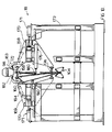
- Figure 1 is a plan view of a carousel apparatus of the invention showing the cathode feed system and discharge system;
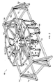
- Figure 2 is a perspective view of the frame of the carousel apparatus;
- Figure 3 is a plan view of the carousel apparatus shown in Figure 2 illustrating the drive mechanism;
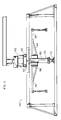
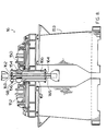
- Figure 4 is a side elevation, partly cut away, of the carousel assembly shown in Figure 3;
- Figure 5 is an enlarged plan view, partly cut away, of the drive mechanism showing partial rotation thereof by ghost lines;
- Figure 6 is a perspective view of the drive mechanism shown in Figure 5;
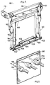
- Figure 7 is a perspective view of a cathode hanger assembly showing a cathode with a metallic sheet deposited thereon in ghost lines;
- Figure 8 is an end elevation of a cathode in an operative position at a hammering station;
- Figure 9 is a perspective view illustrating the operation of opposed hammers at the hammering station depicted in Figure 8;
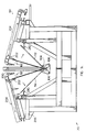
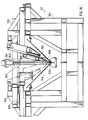
- Figure 10 is an end elevation of a cathode in its operative position at the opening station;
- Figure 11 is an enlarged end elevation of a cathode at the opening station;
- Figure 12 is an end elevation of an upper portion of a cathode at the opening station illustrated in Figures 10 and 11 showing the interaction of grippers with the upper edges of the metallic sheets;
- Figure 13 is an end elevation of a cathode at an optional additional full-opening station depicted in Figure 1 showing the partially separated metallic strips preparatory to stripping by peeling from the cathode when required;
- Figure 14 is an end elevation of a cathode showing the pair of metallic strips fully detached from the cathode;
- Figure 15 is an end elevation of the lower portion of a cathode having the metallic sheets pivoted into abutment with the cathode preparatory to bottom discharge into the sheet rotator for substantially horizontal discharge;
- Figure 16 is an enlarged end elevation of a cathode with metallic sheets pivoted thereagainst, as shown in Figure 15, indicating opening of the bottom V-support by ghost lines;
- Figure 17 is an end elevation, partly cut away, of a portion of a stack of alternate corrugated and uncorrugated pairs of metallic sheets, with strapping; and
- Figure 18 is a side elevation of an optional separation station.
- With reference to Figure 1 of the drawings, the apparatus for stripping metal sheets from cathodes generally comprises a
multi-sided carousel 10 having, in the embodiment illustrated, 12 sides, rotated aboutcentral support shaft 12 to convey cathodes having electrodeposited metal sheets on opposite sides thereof in a clockwise direction as viewed in Figure 1 sequentially past a number of station locations. The stations in this particular embodiment include loadingstation 14, hammeringstation 16,opening station 18, full-opening station 20,separation station 22,discharge station 24,inspection station 25,cathode exchange station 26 andcathode unloading station 28. - A load of cathodes bearing electrodeposited metal sheets, after washing, is loaded onto a
carrier car 30 mounted for reciprocal travel on thetop rails 32 of a transporter frame for transportation of the bundle to rotating and loweringtransfer assembly 34. The bundle of cathodes, usually containing 44 cathodes, is rotated through about 30° by rotating and loweringassembly 34 onto chain conveyor depicted bynumeral 36. A complete bundle of cathodes is deposited onchain conveyor 36 which advances the bundle towardsloading station 14. Anoverhead walking beam 38 picks up a cathode for advancement onto a fixed beam with repeat of this motion until the cathode is transferred onto the hanger of the carousel at loadingstation 14 for sequential advancement through each station for eventual discharge of stripped sheets fromdischarge station 24 and removal of stripped cathodes atcathode unloading station 28. - With particular reference now to Figures 2-6, the
carousel 10 comprises asupport frame 50 having rigid steel structural corner posts 52, diagonal reinforcinggussets 54 bolted or welded tolateral beams 56, andlongitudinal beams 58. Rectangulartransverse beams 60, shown most clearly in Figures 3 and 4,support drive assembly 62. Uprightcentral shaft 70 is mounted at its lower end onbase 72 having a bearing, not shown, for rotation thereon and is supported at its upper end by bearing 74 mounted inhousing 76 supported bytransverse beams 60. - Radial beams 78 secured at their inner ends to
collar 80, which in turn is secured to acolumn 82 forming part ofshaft 70, are supported bydiagonal struts 84 extending between the base ofcollar 80 and an intermediate point onradial beams 78.Peripheral beams 86 interconnect the outer ends ofbeams 78 to define a side of the multi-sided carousel and support an equal number ofcathode hangers 88, three of which are shown in Figure 2. - Each
cathode hanger 88, details for which are shown in Figure 7, comprises downwardly extending side-arms 90 rigidly interconnected tobeams 86 byplates 92 welded thereto. An L-shapedhanger bracket 94 welded to the inner side of each ofarms 90 is adapted to receivehanger bar 96 secured to the top edge ofcathode 98, shown by ghost lines.Cathode 98 and its construction are disclosed in detail in applicant's U.S. Patent No. 4,882,027. - A pair of spaced apart
transverse rods 100 are mounted for rotation inbushings 102 rigidly secured to the underside ofarms 90 to carry V-support 104. Each V-support 104 comprises a pair of opposedupper plates 106 rigidly interconnected to their respectivetransverse rods 100 by spaced apartplates 108, for reasons which will become apparent as the description proceeds. - It will be observed that the conterminous
bottom edges 110 ofcathode 98 andmetallic sheets support 104. - The
carousel 10 is driven in a clockwise direction, as viewed in Figures 5 and 6 of the drawings, by a Geneva-typeindexing drive assembly 62 which comprises anhydraulic motor 120 driving via a counter-clockwise rotating shaft 132 atorque arm drive 122 having a pair of downwardly extendingroller subshafts radial slots 128 formed in theGeneva drive wheel 130, as shown most clearly by the ghost lines in Figure 5. TheGeneva drive wheel 130 has twelveradial slots 128 spaced 30° apart, one for each of the twelve station locations, to permit accurate inexing of a cathode hanger on the carousel into each station. At the time when bothrollers wheel 130 and consequently the entire carousel assembly, are stationary. At these junctures, the cathode hangers are correctly positioned within a station and thedrive 120 is stopped for a predetermined period of time to allow the desired functions to occur at the plurality of stations. -
Cathodes 98 havingmetallic sheets cathode hanger assembly 88 at loadingstation 14.Hanger bar 96 is supported at each end inhanger brackets 94 withbottom edges 110 suspended above V-support 104. The transfer of acathode 98 onto hanger brackets preferably is completed in about 2.5 seconds within a minimum cycle time at each station of about 4.5 seconds, thus allowing about 2.0 seconds for transfer to and indexing of the cathode hanger and cathode at the next station.Cathode 98 is then advanced to hammeringstation 16 by rotation ofdrive assembly 62 for breaking the adhesion of the upper edges of the deposited metal sheets to the cathode. - Turning now to Figures 8 and 9, hammering
station 16 comprises a pair of opposed, reciprocally mountedcarriages frame 153 adapted to be extended towards and retracted away fromcathode 98 such that opposed air hammers 154, 156 supported thereby will, upon actuation, strikemetallic sheets cathode 98 in proximity to theupper edges opposed clamps vertical support members carriages cathode 98 during the hammering operation while the lower pair ofopposed clamps sheets - The hammering operation normally releases the
upper edges cathode 98 whereby flexing of the cathode, shown in Figures 10-12, at theopening station 18 frees oneupper edge 160 and then the secondupper edge 158 fromcathode 98. With particular reference to Figure 10, theopening station 18 comprises a pair ofopposed carriages guide frame 170 by the actuation of piston-cylinder assemblies 171 mounted onframe 173. The right hand portion of the figure shows polyurethane-coveredupper clamp 172 adapted to rigidly engage the upper portion ofcathode 98 above theupper edges cathode 98 andmetal sheets support 104.Piston cylinder assembly 176, carried bycarriage 168, permits initial extension ofcentral push bar 180 to the position depicted in Figure 10, and by ghost lines in Figure 11, thereby bending the cathode to separate loosenedupper edge 160 fromcathode 98. The deflection ofcathode 98 opens theupper edge 160 from cathode 98 a sufficient distance to allow the insertion offinger 182 on the side opposite to bar 180 into the said opening by actuation of piston-cylinder 184. - Piston-
cylinder assembly 176 is then retracted and the procedure repeated on the opposite side ofcathode 98 by actuating an opposite piston-cylinder assembly, not shown, to defectcathode 98 in the opposite direction for separation of the loosenedupper edge 158 fromcathode 98 to create an opening into whichfinger 183 is inserted in like manner, as illustrated in Figure 12. - Upon completion of the insertion of the
fingers upper edges cathode 98, thefingers carriages upper edges passive guides 192 which extend along arcs around the circumference of the carousel to the next station to engage and prevent saidupper edges cathode 98 during rotation and indexing of the carousel to the next station. Passive guides 190, one of which is shown, extend along arcs around the circumference of the carousel to the next station on each side of thecathode 98 to support the metallic sheets, as shown by ghost lines in Figure 10, in the event a sheet is completely freed from the cathode as is normally the case. - Turning now to Figures 13 and 14, in case of partial stripping only, the cathode with partially opened metallic sheets is next positioned at
station 20 where a pair of opposed reciprocating carriages mounted on opposite side of the cathode are normally in an at-rest position with strippingfingers fingers carriages 204 which are reciprocally mounted onframe 206 to peel the metallic sheets from the cathode upon retraction of the saidfingers Inner finger 202, upon complete retraction ofcarriage 204 as shown by ghost lines in Figure 14, is withdrawn sufficiently to allowmetallic sheets passive guide rails 210 which extend in an arc to the discharge station. The lower ends ofmetallic sheets cathode 98 and drop onto the V-support 104, the angle sub-tended betweenplates 106 being about the same as the angle assumed between the metallic sheets fully opened. -
Separation station 22, which may be located after full-opening station 20, may be used for stripping of relatively flexible electrodeposited sheets such as thin copper sheets or zinc sheets which do not have the stiffness of normal thickness copper sheets. The separating mechanism atstation 22 comprisesframe 191 andcarriages cathode 98 by actuation of piston-cylinder assemblies 195, one of which is shown, whereby the upper end of partially strippedcathode 98 can be rigidly gripped betweenopposed clamps knives 198 supported by piston-cylinder assembly 199, one of which is shown are then simultaneously lowered between the electrodeposited sheets and the cathode to complete stripping of the said sheets to the bottom of the cathode. This is illustrated in Figure 18. -
Cathodes 98 havingmetallic sheets support 104 are indexed to dischargestation 24, shown more clearly in Figure 15, for horizontal discharge from the stripping apparatus.Station 24 comprises a pair of opposedhydraulic rams 220 mounted for extension and retraction on support frames 222 and each actuated bypiston 224 extending fromcylinder 226. Strippedmetallic sheets cathode 98 for vertical alignment followed by opening of V-support 104, as illustrated by the ghost lines in Figure 16 by rotation ofrods 100 and pivoting ofplates 106 away from each other by actuating means, not shown, located atstation 24.Metallic strips opposed rollers 230 journaled at the ends oframs 220. Lower support assembly orenvelope 232 is rotated through about 90° in a clockwise direction as viewed in Figure 15 to the position depicted byghost lines 232a and the pair of abutting metallic sheets ejected byhydraulic ram 234 to the position depicted bynumerals - The stripped cathode may then be indexed through
inspection station 25 to a reject andreplacement station 26 for substitution of damaged cathodes. - The carousel is then indexed to a
cathode unloading station 28 for sequential loading and discharge of the cathodes onto a chain conveyor for accumulation of a full load of cathodes for removal from the stripping assembly and transfer to a tankhouse for reuse. - The stripped metallic sheet travels in pairs from the
discharge station 24 by means of a shuttle conveyor onto a 100tonne corrugating press 250. Every second pair of metallic sheets is corrugated and the alternate corrugated and planar pairs of sheets moved onto a set of trip rolls which deposits the sheets onto astacker lift 252 at the cycle rate of about 4.5 seconds per double sheet. - The
stacker lift 252 comprises a lowering assembly which lowers the bundle as it is formed so that the distance between the trip rolls and the top of the bundle remains constant. When the required quantity of pairs of metallic sheets, i.e.planar sheets corrugated sheets chain conveyor 254 for transfer to weightlift 256 andstrapper lift 258. The lowering assembly is returned to its uppermost position to receive pairs of metallic sheets for the next bundle. - After weighing of the bundle by conventional weighing equipment at
lift 256, the bundle normally is placed on a pair of wood blocks, not shown, and compressed prior to wrapping and clampingsteel straps 115 about the bundle. - The invention permits achievement of a number of important advantages. Cathodes such as stainless steel cathodes having copper sheets electrodeposited thereon can be quickly and positively stripped of the sheets without damage to the cathodes or sheets permitting an effective and reliable operation. Automation of the operation minimizes or eliminates manual operations to increase rate of productivity while obviating many hazards. The carousel configuration minimizes space requirements for important savings in construction costs.
- The bundles of product metallic sheet stacked and bound in alternate layers of pairs of corrugated and uncorrugated or planar sheets provide continuous elongated air gaps extending from one end of the bundle to other to enhance the rate of heat transfer in a subsequent melting operation.
Claims (11)
- A method of stripping electrodeposited metal sheets (112,114) from cathodes (98), each cathode (98) having a hanger bar (96) for supporting the cathode (98) vertically on the periphery of a rotatable carousel (10), which method comprises:
sequentially feeding the cathodes (98) onto the carousel (10) at a loading station (14);
rotating the carousel (10) to transfer a cathode (98) from the loading station (14) to a hammering station (16) for loosening of upper edges (158,160) of the electrodeposited sheets (112,114) from the cathode (98);
rotating the carousel (10) to transfer the cathode (98) to an opening station (18) for stripping the sheets (112,114) from the cathode (98) by rigidly clamping the cathode (98) above the upper edges (158,160) of the sheets (112,114) and clamping the lower ends of the sheets (112,114), flexing the cathode (98) in a first direction by extending a first push bar (180) to form a gap between the cathode (98) and the upper edge (158, 160) of the sheet on the opposite side of the cathode (98) to the first push bar (180) and inserting at least one finger (182) into said gap, flexing the cathode (98) in the opposite direction by retracting the first push bar (180) and extending a second push bar to form a gap between the cathode (98) and the upper edge (158,160) of the sheet on the opposite side of the cathode (98) to the second push bar and inserting at least one finger (183) into said gap, and then retracting the second push bar and the fingers (182,183) to strip the sheets (112,114) from the cathode (98);
rotating the carousel (10) to transfer the cathode (98) to a discharge station (24) for discharging stripped sheets (112,114); and
rotating the carousel (10) to transfer the stripped cathode (98) to an unloading station (28) for removal of stripped cathodes (98). - A method according to claim 1, wherein between the opening station (18) and the discharge station (24) there is provided an additional full-opening station (20) and/or a separation station (22) at which the stripping is completed through the use of retractable fingers (200, 202) and/or stripping knives (198) if the sheets (112,114) are only partially stripped from the cathode (98) at the opening station (20).
- A method according to claim 1 or claim 2, wherein the stripped sheets (112,114) are discharged at the discharge station (24) by pushing the sheets (112,114) against the cathode (98) into vertical alignment and dropping the sheets (112,114) by gravity as a pair into a vertical envelope (232), rotating the envelope (232) to a substantially horizontal position and ejecting the pair of sheets (112,114) therefrom.
- A method according to claim 3, wherein alternate pairs of sheets (112,114) ejected from the discharge station (24) are corrugated and stacked with alternate pairs of non-corrugated planar sheets (112,114) and strapped together to form a bundle.
- Apparatus for stripping electrodeposited metal sheets (112,114) from cathodes (98), the apparatus comprising:
a carousel (10) mounted for 360° rotation;
means (38) for charging the cathodes (98) one by one onto the carousel (10) and means (88) for supporting the cathodes (98) vertically at the periphery of the carousel (10);
a loading station (14) at which the cathodes (98) having electrodeposited metal sheets (112,114) thereon are charged onto the carousel (10);
a hammering station (16) for loosening the upper edges (158,160) of the sheets (112,114) from the cathodes (98);
an opening station (18) comprising a pair of opposed reciprocally mounted carriages (168,169) for receiving a cathode (98) therebetween, each carriage (168,169) having an upper clamp (172) for abutting the cathode (98) above the upper edge (158,160) of an electrodeposited sheet (112,114) and a lower clamp (174) for abutting the sheet (112,114) in proximity to its lower edge, a central push bar (180) for independent actuation, and a downwardly depending finger (182,183) pivotally mounted at the top of the carriage (168,169), whereby the cathode (98) can be rigidly clamped between the upper clamps (172) and the sheets (112,114) in proximity to their lower ends, clamped by the lower clamps (174) upon extension of the carriages (168,169) towards each other, and flexed in one direction by extending one push bar (180) so as to form a gap between the cathode (98) and the upper edge (158,160) of the sheet on the opposite side of the cathode (98) to that push bar (180), whereupon a said downwardly depending finger (182,183) can be inserted into the gap, and the cathode (98) can be flexed in the opposite direction by extending the other push bar (180) so as to form a gap between the cathode (98) and the upper edge (158,160) of the other sheet, whereupon the other downwardly depending finger (182,183) can be inserted into the gap, and the carriages (168,169) with the fingers (182,183) can be retracted to strip the sheets (112,114) from the cathode (98);
a discharge station (24) for discharging the sheets (112,114); and
an unloading station (28) for removal of stripped cathodes (98);
wherein the said stations are located at the periphery of the carousel (10), and the apparatus includes means (62) for rotating the carousel (10) to sequentially advance the cathodes (98) through the stations. - Apparatus according to claim 5, wherein the carousel (10) is multi-sided and the means (88) on the carousel (10) for supporting the cathodes (98) at the periphery of the carousel (10) comprises a pair of downwardly extending side arms (90), spaced apart for receiving a cathode (98) therebetween, secured to the carousel (10) at each of the sides thereof, a hanger bracket (94) secured to each side arm (90) in proximity to its upper end for supporting a hanger bar (96) of a cathode (98), a V-support (104), having an apex, secured at opposite ends to the lower ends of the side arms (90) of each pair below the bottom of a cathode (98), and means (100,106) for opening the V-supports (104).
- Apparatus according to claim 5 or claim 6, further comprising a full-opening and/or a separation station (20,22) between the opening station (18) and the discharge station (24) for ensuring completion of stripping of metal sheets (112,114) from the cathodes (98) prior to discharge through the use of retractable fingers (200,202) and/or stripping knives (198) if the sheets (112,114) are only partially stripped from a cathode (98) at the opening station (18).
- Apparatus according to any one of claims 5 to 7, wherein the hammering station (16) comprises a pair of opposed reciprocally mounted carriages (150,152) for receiving a cathode (98) therebetween, each having a plurality of air hammers (154,156) which can be extended towards and retracted away from the cathode (98) whereby the air hammers (154,156) strike the sheets (112,114) in proximity to the upper edges (158,160) of the sheets (112,114) for loosening of the upper edges (158,160) from the cathode (98).
- Apparatus according to any one of claims 5 to 8, wherein the discharge station (24) is a bottom discharge station for discharging pairs of metallic sheets (112,114), and means (232) are provided in the bottom discharge station (24) for receiving pairs of vertically-aligned metallic sheets (112,114), for rotating the sheets (112,114) to a horizontal position, and for discharging the pairs of metallic sheets (112,114) horizontally from the carousel (10).
- Apparatus according to any one of claims 5 to 9, further comprising means (250) for corrugating alternate pairs of metallic sheets (112,114) discharged at the discharge station (24), means (252) for stacking the alternate pairs of corrugated and uncorrugated sheets (112,114) and means for bundling the stack.
- Apparatus according to any one of claims 5 to 10, wherein each said push bar (180) has a piston-cylinder assembly (176) connected thereto.
Priority Applications (6)
| Application Number | Priority Date | Filing Date | Title |
|---|---|---|---|
| US07/598,369 US5149410A (en) | 1990-10-25 | 1990-10-16 | Cathode stripping apparatus |
| AU64912/90A AU625243B2 (en) | 1990-10-25 | 1990-10-23 | Cathode stripping apparatus |
| DE69024356T DE69024356T2 (en) | 1990-10-25 | 1990-10-25 | Device for stripping cathodes |
| EP90311692A EP0482258B1 (en) | 1990-10-25 | 1990-10-25 | Cathode stripping apparatus |
| ES90311692T ES2085899T3 (en) | 1990-10-25 | 1990-10-25 | METHOD AND APPARATUS FOR THE SEPARATION OF CATHODIC ELECTROPOSED SHEETS, ESPECIALLY COPPER SHEETS ELECTROPOSED ON STEEL. |
| CA002041927A CA2041927C (en) | 1990-10-16 | 1991-05-07 | Cathode stripping apparatus |
Applications Claiming Priority (1)
| Application Number | Priority Date | Filing Date | Title |
|---|---|---|---|
| EP90311692A EP0482258B1 (en) | 1990-10-25 | 1990-10-25 | Cathode stripping apparatus |
Publications (2)
| Publication Number | Publication Date |
|---|---|
| EP0482258A1 EP0482258A1 (en) | 1992-04-29 |
| EP0482258B1 true EP0482258B1 (en) | 1995-12-20 |
Family
ID=8205588
Family Applications (1)
| Application Number | Title | Priority Date | Filing Date |
|---|---|---|---|
| EP90311692A Expired - Lifetime EP0482258B1 (en) | 1990-10-16 | 1990-10-25 | Cathode stripping apparatus |
Country Status (5)
| Country | Link |
|---|---|
| US (1) | US5149410A (en) |
| EP (1) | EP0482258B1 (en) |
| AU (1) | AU625243B2 (en) |
| DE (1) | DE69024356T2 (en) |
| ES (1) | ES2085899T3 (en) |
Cited By (1)
| Publication number | Priority date | Publication date | Assignee | Title |
|---|---|---|---|---|
| US7306706B2 (en) | 2004-01-21 | 2007-12-11 | Falconbridge Limited | Method and apparatus for stripping electrodeposited metal sheets from permanent cathodes |
Families Citing this family (15)
| Publication number | Priority date | Publication date | Assignee | Title |
|---|---|---|---|---|
| US5951763A (en) * | 1998-02-09 | 1999-09-14 | Knox; David J. | Immersible rotatable carousel apparatus for wetting articles of manufacture |
| US7014036B2 (en) | 2002-11-27 | 2006-03-21 | Falconbridge Limited | Cathode linear conveyer assembly |
| FI116572B (en) * | 2004-08-27 | 2005-12-30 | Outokumpu Oy | Apparatus and method for treating metal sheets |
| CA2568484C (en) * | 2006-11-22 | 2013-01-29 | Stephan Frank Matusch | High capacity anode preparation apparatus |
| AU2008286233B2 (en) * | 2007-08-07 | 2011-06-16 | Xstrata Technology Pty Ltd | Apparatus for stripping metal from a cathode plate |
| US8337679B2 (en) | 2007-08-24 | 2012-12-25 | Epcm Services Ltd. | Electrolytic cathode assemblies and methods of manufacturing and using same |
| EP2141265A1 (en) | 2008-07-04 | 2010-01-06 | Technic One S.A. | Stripping apparatus and method for removing an electrodeposited metal layer from a cathode plate |
| CN101717973A (en) * | 2009-12-23 | 2010-06-02 | 江西瑞林装备技术有限公司 | Stripping device for stainless steel cathode |
| JP2013040366A (en) * | 2011-08-12 | 2013-02-28 | Mesco Inc | Apparatus for stripping off electrodeposited metal and method for stripping off electrodeposited metal |
| CN105506677B (en) * | 2015-12-25 | 2018-05-25 | 河南豫光冶金机械制造有限公司 | The stripping off device of electro-deposition rolled tin on releasing cathode plates |
| JP6637868B2 (en) * | 2016-10-19 | 2020-01-29 | パンパシフィック・カッパー株式会社 | Electrodeposited metal laminating method and laminating apparatus |
| CN108251867B (en) * | 2017-12-18 | 2023-05-12 | 金川集团股份有限公司 | Auxiliary device is peeled off to starting sheet |
| PH12021550336B1 (en) | 2018-08-21 | 2024-02-28 | Glencore Tech Pty Ltd | Stripping of metal from cathodes |
| CN113502509B (en) * | 2021-08-04 | 2022-05-13 | 重庆有研重冶新材料有限公司 | An automatic powder scraping device for electrolytic copper powder |
| CN113846356B (en) * | 2021-09-28 | 2023-01-06 | 三门三友科技股份有限公司 | Cathode stripping device and method |
Family Cites Families (7)
| Publication number | Priority date | Publication date | Assignee | Title |
|---|---|---|---|---|
| US3953312A (en) * | 1972-04-19 | 1976-04-27 | Mitsui Mining & Smelting Co., Ltd. | Apparatus for peeling electrodeposited metal off cathode base plate |
| JPS51114303A (en) * | 1975-03-31 | 1976-10-08 | Mitsui Mining & Smelting Co Ltd | Method and apparatus for stripping electric plating metal |
| US4049527A (en) * | 1976-01-08 | 1977-09-20 | Mitsui Mining & Smelting Co., Ltd. | Electrodeposited metal plate peeling-off machine |
| CA1214432A (en) * | 1983-02-14 | 1986-11-25 | George H. Reeves | Method and apparatus for stripping cathodes |
| AU594208B2 (en) * | 1986-11-04 | 1990-03-01 | Mount Isa Mines Limited | A method of stripping electrolytically deposited copper from a cathode |
| GB2196989B (en) * | 1986-11-04 | 1990-07-04 | Mim Techn Marketing Ltd | A method of stripping electrolytically deposited copper from a cathode |
| AU601825B2 (en) * | 1987-03-19 | 1990-09-20 | Galvanizing Industries Pty. Ltd. | Carousel assembly for a galvanizing process |
-
1990
- 1990-10-16 US US07/598,369 patent/US5149410A/en not_active Expired - Lifetime
- 1990-10-23 AU AU64912/90A patent/AU625243B2/en not_active Ceased
- 1990-10-25 ES ES90311692T patent/ES2085899T3/en not_active Expired - Lifetime
- 1990-10-25 DE DE69024356T patent/DE69024356T2/en not_active Expired - Fee Related
- 1990-10-25 EP EP90311692A patent/EP0482258B1/en not_active Expired - Lifetime
Cited By (1)
| Publication number | Priority date | Publication date | Assignee | Title |
|---|---|---|---|---|
| US7306706B2 (en) | 2004-01-21 | 2007-12-11 | Falconbridge Limited | Method and apparatus for stripping electrodeposited metal sheets from permanent cathodes |
Also Published As
| Publication number | Publication date |
|---|---|
| ES2085899T3 (en) | 1996-06-16 |
| AU6491290A (en) | 1992-04-30 |
| DE69024356T2 (en) | 1996-06-05 |
| EP0482258A1 (en) | 1992-04-29 |
| US5149410A (en) | 1992-09-22 |
| DE69024356D1 (en) | 1996-02-01 |
| AU625243B2 (en) | 1992-07-02 |
Similar Documents
| Publication | Publication Date | Title |
|---|---|---|
| US5149410A (en) | Cathode stripping apparatus | |
| JPS59197586A (en) | Method and apparatus for cleaning cathode and/or anode plates | |
| JP6106886B1 (en) | Sheet material sorting equipment | |
| WO2025194632A1 (en) | Automatic smc-sheet compression molding production line, and automatic material conveying method therefor | |
| JP2002137823A (en) | Automatic supply device, and automatic cutting device for reinforcing bar | |
| CA1183066A (en) | Electrode brushing apparatus | |
| US3039626A (en) | Mat handling machine | |
| CA2041927C (en) | Cathode stripping apparatus | |
| US12031223B2 (en) | Stripping of metal from cathodes | |
| JPH0684552B2 (en) | Method and apparatus for peeling electrodeposited metal sheet from cathode | |
| CN210681293U (en) | Boxing mechanism for expansion bolt boxing and packaging | |
| GB2074064A (en) | Method and device for straightening supporting bars removed from the cathode plates in electrolytic refining plants | |
| FI94153C (en) | Method and apparatus for peeling discs from cathodes | |
| JP6637868B2 (en) | Electrodeposited metal laminating method and laminating apparatus | |
| JP7676958B2 (en) | Cross beam receiving device | |
| CN210338549U (en) | Empty can full-automatic packaging system | |
| NO303072B1 (en) | Method and apparatus for extracting galvanically applied metal layers from cathodes | |
| JP2885501B2 (en) | Can lid transfer device | |
| CN219278686U (en) | Automatic change metal sheet material receiving stacker | |
| CN219597907U (en) | Waste collection mechanism of crawler belt iron core stripping device | |
| JPS62188792A (en) | Method and apparatus for separating electrolytic fused metal | |
| JP3767870B2 (en) | Corrugated rebar mat manufacturing equipment | |
| JPS61502053A (en) | Device for stacking thin sections | |
| EA041998B1 (en) | REMOVAL OF METAL FROM CATHODES | |
| US3622148A (en) | Conveyor system for production of corrugated sheets from fibrocement, particularly, asbestoscement |
Legal Events
| Date | Code | Title | Description |
|---|---|---|---|
| PUAI | Public reference made under article 153(3) epc to a published international application that has entered the european phase |
Free format text: ORIGINAL CODE: 0009012 |
|
| AK | Designated contracting states |
Kind code of ref document: A1 Designated state(s): BE DE ES FR GR IT SE |
|
| 17P | Request for examination filed |
Effective date: 19920604 |
|
| 17Q | First examination report despatched |
Effective date: 19930815 |
|
| GRAA | (expected) grant |
Free format text: ORIGINAL CODE: 0009210 |
|
| AK | Designated contracting states |
Kind code of ref document: B1 Designated state(s): BE DE ES FR GR IT SE |
|
| PG25 | Lapsed in a contracting state [announced via postgrant information from national office to epo] |
Ref country code: GR Free format text: LAPSE BECAUSE OF FAILURE TO SUBMIT A TRANSLATION OF THE DESCRIPTION OR TO PAY THE FEE WITHIN THE PRESCRIBED TIME-LIMIT Effective date: 19951220 |
|
| ITF | It: translation for a ep patent filed | ||
| REF | Corresponds to: |
Ref document number: 69024356 Country of ref document: DE Date of ref document: 19960201 |
|
| ET | Fr: translation filed | ||
| REG | Reference to a national code |
Ref country code: ES Ref legal event code: FG2A Ref document number: 2085899 Country of ref document: ES Kind code of ref document: T3 |
|
| PLBE | No opposition filed within time limit |
Free format text: ORIGINAL CODE: 0009261 |
|
| STAA | Information on the status of an ep patent application or granted ep patent |
Free format text: STATUS: NO OPPOSITION FILED WITHIN TIME LIMIT |
|
| 26N | No opposition filed | ||
| PGFP | Annual fee paid to national office [announced via postgrant information from national office to epo] |
Ref country code: DE Payment date: 20081029 Year of fee payment: 19 |
|
| PGFP | Annual fee paid to national office [announced via postgrant information from national office to epo] |
Ref country code: ES Payment date: 20081127 Year of fee payment: 19 Ref country code: BE Payment date: 20080929 Year of fee payment: 19 |
|
| PGFP | Annual fee paid to national office [announced via postgrant information from national office to epo] |
Ref country code: IT Payment date: 20081010 Year of fee payment: 19 Ref country code: SE Payment date: 20081022 Year of fee payment: 19 |
|
| PGFP | Annual fee paid to national office [announced via postgrant information from national office to epo] |
Ref country code: FR Payment date: 20081029 Year of fee payment: 19 |
|
| BERE | Be: lapsed |
Owner name: *FALCONBRIDGE LTD Effective date: 20091031 |
|
| EUG | Se: european patent has lapsed | ||
| REG | Reference to a national code |
Ref country code: FR Ref legal event code: ST Effective date: 20100630 |
|
| PG25 | Lapsed in a contracting state [announced via postgrant information from national office to epo] |
Ref country code: FR Free format text: LAPSE BECAUSE OF NON-PAYMENT OF DUE FEES Effective date: 20091102 Ref country code: DE Free format text: LAPSE BECAUSE OF NON-PAYMENT OF DUE FEES Effective date: 20100501 |
|
| PG25 | Lapsed in a contracting state [announced via postgrant information from national office to epo] |
Ref country code: BE Free format text: LAPSE BECAUSE OF NON-PAYMENT OF DUE FEES Effective date: 20091031 |
|
| PG25 | Lapsed in a contracting state [announced via postgrant information from national office to epo] |
Ref country code: IT Free format text: LAPSE BECAUSE OF NON-PAYMENT OF DUE FEES Effective date: 20091025 |
|
| REG | Reference to a national code |
Ref country code: ES Ref legal event code: FD2A Effective date: 20110407 |
|
| PG25 | Lapsed in a contracting state [announced via postgrant information from national office to epo] |
Ref country code: SE Free format text: LAPSE BECAUSE OF NON-PAYMENT OF DUE FEES Effective date: 20091026 |
|
| PG25 | Lapsed in a contracting state [announced via postgrant information from national office to epo] |
Ref country code: ES Free format text: LAPSE BECAUSE OF NON-PAYMENT OF DUE FEES Effective date: 20110324 |
|
| PG25 | Lapsed in a contracting state [announced via postgrant information from national office to epo] |
Ref country code: ES Free format text: LAPSE BECAUSE OF NON-PAYMENT OF DUE FEES Effective date: 20091026 |