EP0481941B1 - Verbindungsblecheinrichtung - Google Patents
Verbindungsblecheinrichtung Download PDFInfo
- Publication number
- EP0481941B1 EP0481941B1 EP91850234A EP91850234A EP0481941B1 EP 0481941 B1 EP0481941 B1 EP 0481941B1 EP 91850234 A EP91850234 A EP 91850234A EP 91850234 A EP91850234 A EP 91850234A EP 0481941 B1 EP0481941 B1 EP 0481941B1
- Authority
- EP
- European Patent Office
- Prior art keywords
- nail
- nails
- plate
- lines
- plate assembly
- Prior art date
- Legal status (The legal status is an assumption and is not a legal conclusion. Google has not performed a legal analysis and makes no representation as to the accuracy of the status listed.)
- Expired - Lifetime
Links
- 238000005452 bending Methods 0.000 claims abstract description 46
- 238000004080 punching Methods 0.000 claims abstract description 23
- 238000005304 joining Methods 0.000 claims abstract description 5
- 230000006835 compression Effects 0.000 claims description 9
- 238000007906 compression Methods 0.000 claims description 9
- 210000001503 joint Anatomy 0.000 claims description 6
- 238000003825 pressing Methods 0.000 claims description 5
- 239000002023 wood Substances 0.000 claims description 5
- 239000004033 plastic Substances 0.000 claims description 4
- 238000004519 manufacturing process Methods 0.000 description 9
- 239000002184 metal Substances 0.000 description 8
- 239000000463 material Substances 0.000 description 4
- 238000000034 method Methods 0.000 description 4
- 238000003466 welding Methods 0.000 description 3
- 238000006073 displacement reaction Methods 0.000 description 2
- 238000010008 shearing Methods 0.000 description 2
- 229910000831 Steel Inorganic materials 0.000 description 1
- 238000003763 carbonization Methods 0.000 description 1
- 238000002485 combustion reaction Methods 0.000 description 1
- 238000005520 cutting process Methods 0.000 description 1
- 238000009826 distribution Methods 0.000 description 1
- 239000011121 hardwood Substances 0.000 description 1
- 230000001788 irregular Effects 0.000 description 1
- 239000002994 raw material Substances 0.000 description 1
- 239000010959 steel Substances 0.000 description 1
Images


Classifications
-
- E—FIXED CONSTRUCTIONS
- E04—BUILDING
- E04B—GENERAL BUILDING CONSTRUCTIONS; WALLS, e.g. PARTITIONS; ROOFS; FLOORS; CEILINGS; INSULATION OR OTHER PROTECTION OF BUILDINGS
- E04B1/00—Constructions in general; Structures which are not restricted either to walls, e.g. partitions, or floors or ceilings or roofs
- E04B1/38—Connections for building structures in general
- E04B1/48—Dowels, i.e. members adapted to penetrate the surfaces of two parts and to take the shear stresses
- E04B1/49—Dowels, i.e. members adapted to penetrate the surfaces of two parts and to take the shear stresses with self-penetrating parts, e.g. claw dowels
-
- F—MECHANICAL ENGINEERING; LIGHTING; HEATING; WEAPONS; BLASTING
- F16—ENGINEERING ELEMENTS AND UNITS; GENERAL MEASURES FOR PRODUCING AND MAINTAINING EFFECTIVE FUNCTIONING OF MACHINES OR INSTALLATIONS; THERMAL INSULATION IN GENERAL
- F16B—DEVICES FOR FASTENING OR SECURING CONSTRUCTIONAL ELEMENTS OR MACHINE PARTS TOGETHER, e.g. NAILS, BOLTS, CIRCLIPS, CLAMPS, CLIPS OR WEDGES; JOINTS OR JOINTING
- F16B15/00—Nails; Staples
- F16B15/0023—Nail plates
- F16B15/003—Nail plates with teeth cut out from the material of the plate
- F16B15/0046—Nail plates with teeth cut out from the material of the plate from the body of the plate
-
- F—MECHANICAL ENGINEERING; LIGHTING; HEATING; WEAPONS; BLASTING
- F16—ENGINEERING ELEMENTS AND UNITS; GENERAL MEASURES FOR PRODUCING AND MAINTAINING EFFECTIVE FUNCTIONING OF MACHINES OR INSTALLATIONS; THERMAL INSULATION IN GENERAL
- F16B—DEVICES FOR FASTENING OR SECURING CONSTRUCTIONAL ELEMENTS OR MACHINE PARTS TOGETHER, e.g. NAILS, BOLTS, CIRCLIPS, CLAMPS, CLIPS OR WEDGES; JOINTS OR JOINTING
- F16B15/00—Nails; Staples
- F16B15/0023—Nail plates
- F16B2015/0061—Multipiece-plates
-
- F—MECHANICAL ENGINEERING; LIGHTING; HEATING; WEAPONS; BLASTING
- F16—ENGINEERING ELEMENTS AND UNITS; GENERAL MEASURES FOR PRODUCING AND MAINTAINING EFFECTIVE FUNCTIONING OF MACHINES OR INSTALLATIONS; THERMAL INSULATION IN GENERAL
- F16B—DEVICES FOR FASTENING OR SECURING CONSTRUCTIONAL ELEMENTS OR MACHINE PARTS TOGETHER, e.g. NAILS, BOLTS, CIRCLIPS, CLAMPS, CLIPS OR WEDGES; JOINTS OR JOINTING
- F16B15/00—Nails; Staples
- F16B15/0023—Nail plates
- F16B2015/0069—Nail plates with nails on both sides
Definitions
- the invention relates to a double-sided connector plate assembly for joining two at least essentially wooden members, the assembly consisting of at least two essentially identical nail plates, each comprising a plurality of longitudinally spaced nails projecting from the nailfree side of each plate, which nails point away from the plane of the plate and have been formed by punching and bending from this plate, whereby the openings left by the punching of the nails and the longitudinally spaced nails form lines of nails, and there is a plurality of such transversely spaced lines of nails in the plate, and all the nails arranged in one nail plate point to the same side of the plane of the plate, and of the two nail plates of the connector plate assembly, the nails of the first nail plate and the nails of the second nail plate form nail pairs, as well as a butt joint carried out by means of this connector plate assembly and a tool for assembling the connector plate assembly of the nail plates.
- connector plates or nail plates for joining essentially wooden members are known.
- the most general structure consists of a metal sheet in which nails have been punched and bent perpendicularly to the sheet.
- Such nail plates in which all the nails point in one direction of the plate, are struck onto the wooden members when the wooden members have been disposed to form the shape of the desired joint.
- the nails of these nail plates are toothed in order to improve the grip, and have been disposed in longitudinal concavity to improve the stiffness of the nail when it is being struck into the wood, as it has been disclosed by the FI patent specification 65643.
- This type of nail plates provide a sufficient joint strength for many purposes of use and they are easy to use.
- the problem described above can be solved by using double-sided connector plates or nail plates.
- the wooden members to be joined consist respectively of at least two pairs of wooden members, the double-sided connector plate being interposed between them.
- a timber joist will then consist of two timber members, placed longitudinally parallel with one of their surfaces facing each other.
- Such a timber is formed or joined to another timber or other timbers by a connector plate, which extends sufficiently far into the area of each timber to be joined to provide the required strength, and inbetween the two timber members of each timber, but at least not significantly outside the interface between the timber members. With this arrangement, no significant metal surface will be apparent.
- Such a structure is described in the FI patent specification 74319, in which the connector member is formed by a nailfree thick and strong frame plate, on each side of which nail plates made of a thinner material by punching and bending have been attached with their nailfree side facing the frame plate.
- a connector plate assembly has been achieved, which has a great strength in the direction of the plate and a high nail density.
- such a connector plate assembly requires the mastering of several production techniques and a number of production steps. Possible errors in these will cause the connector plate assembly to break under too small a load. The same problems are even more accentuated in connector plates, in which the nails have been directly welded to the frame plate, because there is a more marked point-wise distribution of the load in these.
- a different double-sided connector plate assembly has been described in the US patent specification 3 841 195.
- the assembly consists of two nail plates, both of which have been manufactured from a metal sheet by punching and bending nails projecting from it. In both the nail plates, the nails are all directed to the same side of the metal sheet.
- the connector plate assembly has then been accomplished by assembling these nail plates with their nailfree backs facing each other and by welding the plates together at the openings left by the punching.
- a welding of this kind is a complicated operation and makes the plate expensive.
- the plate also has a poor strength or at least unreliable strength properties, since the local weldings break easily under the heavy load they are submitted to.
- the nail plates may shear from each other along the plane between them, since only the welds support the load in that direction.
- a more serious drawback occurs when the load acts on the nail inserted into the wood, and there are deformations of the nail plate, such as a deflection in the environment of this nail. This is due to the fact that the welds joining the nail plates are at a distance from the nails, so that the nail points do not fit tightly.
- the connector plate assembly consists of two nail plates, as above.
- the nail plates have been formed by perforating and bending projecting nails from a metal sheet, and the nails point only to the one side of the plate. Separate holes have also been punched in the nail plate, the arrangement of the holes corresponding to that of the nails and the holes having such dimensions that the nails pass easily through the holes without however allowing any considerable play.
- the connector plate assembly has been formed from these two nail plates by interlocking them with the surfaces on the side of the nails facing each other, whereby the nails pass through the said holes of the other nail plate and project from the nailfree side of it.
- This connector plate assembly has an excellent strength with regard to the shearing described above, since a shearing along the plane between the nail plates would require that all the nails break.
- a connector plate assembly is strong when submitted to tensile and compressive stress, but extremely weak with regard to bending and especially to torsion.
- the nail density will be very low in the described structure, since the holes occupy the area of the plate, and thus the adhesion to the wooden members will be poor.
- the described structure also necessarily involves the inconvenience of the plate portion being loosely fitted at each nail when the connector plate assembly is being pressed between the wooden members, so that the joint tends to open up slightly after the compression. In this structure, the problem is even more serious than in the case of the US patent specification 3 841 195, since the plates have not been attached to each other, but both the plates may deform regardless of each other.
- a connector plate similar to that disclosed in US 4 486 115 is described in GB-A 1 287 739.
- the connector comprises a plate formed with teeth pressed out from the plate on one side only, and slots other than the holes left by the teeth.
- the slots and teeth are arranged such that two similar plates can be coupled together with the teeth of each plate passing through the slots of the other plate, to form a combined connector with teeth on opposite sides.
- the object of the invention is to provide a double-sided connector plate assembly, which is very resistant to tactile, compressive, flexural and torsion stress, and which permits to arrange as high a nail density as is generally possible by punching and bending.
- the object of the invention is also a connector plate assembly, which transfers the loads to the plate portion efficiently and without breaking and in which the plate portion has a good total strength.
- the object of the invention is a connector plate assembly, in which there is essentially no deformation of the plate portion, or a very slight deformation at each nail, when the connector plate assembly is being pressed inbetween the wooden members.
- the object of the invention is to provide a connector plate assembly of the type described above, which is easy to manufacture at a low cost.
- the object of the invention is to provide a tool, by means of which the connector plate assembly of the above type can be easily, rapidly and reliably assembled ready for use, and to achieve a perfectly strong joint that provides fire safety.
- a connector plate assembly which is characterized by the features defined in the characterizing part of claim 1, by a joint using this connector plate assembly, which is characterized by the features defined in the characterizing part of claim 12, and by a fixing tool, which is characterized by the features defined in the characterizing part of claim 14.
- Figures 1A and 1B show a cross-section of one embodiment of the connector plate assembly according to the invention along the lines A and B respectively of the nail plate in figure 2.
- Figure 2 shows a nail plate produced by the connector plate assembly of figures 1A and 1B seen from the toothed side towards its surface.
- Figures 3A and 3B show a cross-section of another embodiment of the connector plate assembly according to the invention along the lines C and repsectively D of the nail plate in figure 4.
- Figure 4 shows the nail plate produced by the connector plate assembly of figures 3A and 3B seen from the toothed side towards its surface.
- Figure 5 shows the structure of figure 1A in the assembling stage of the nail plates.
- Figure 6 shows the connector plate assembly of figures 1A and 1B in the same perspective as in figure 2.
- Figure 7 shows a nail plate produced by a third embodiment of the connector plate assembly according to the invention seen from the toothed side towards its surface.
- Figure 8 shows the connector plate assembly carried out with the nail plate of figure 7, in the same perspective.
- Figure 9 shows a detail of the joint area between the nail root and the plate portion in one embodiment of the invention seen in the plane II-II of figure 10.
- Figure 10 shows a detail of figure 9 along the plane I-I of figure 9.
- Figure 11 shows an axonometric view of the press member of the fixing tool according to the invention.
- Figure 12 shows a fire-safe butt joint according to the invention perpendicularly to the plane of the connector plate.
- Figure 13 shows a nail plate produced by a fourth embodiment of a connector plate assembly according to the invention, seen from the toothed side towards its surface.
- Figure 14 shows a cross-section of a connector plate assembly carried out with the nail plate of figure 13 along the line K/L′-K/L′ of figure 15.
- Figure 15 shows the connector plate assembly carried out with the nail plate of figure 13 in the same perspective.
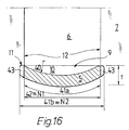
- Figure 16 shows a detail of another preferred embodiment of the nail intended for the connector plate assembly according to the invention.
- figure 4 shows the nail plate 4, which is formed by a metal and typically steel sheet, from which nails 5, shown by oblique lines, have been perforated and bent in a manner known per se.
- the nail plate 4 has been illustrated from the toothed side, i.e. the nails 5 point upwards.
- the position of the nail plate in figure 2 corresponds to the lower nail plate 4 of the connector plate assembly in figures 1A and 1B, in which the nails point upwards and the nail plate of figure 4 corresponds to the lower nail plate 4 of the connector plate assembly of figures 3A and 3B, in which the nails also point upwards
- the nail plate of figure 13 corresponds to the lower nail plate 4 of the connector plate assembly of figure 14.
- FIGS. 1A-8 and 13-15 show that the perforation and bending of the nails has left nail-shaped openings 6 in the plate portion.
- FIGS 1A-8 and 13-15 the nails and the openings are presented only with regard to their positioning, their shape not complying with the preferred embodiments of the invention, which appear in figures 9, 10 and 16.
- the width of the nails is indicated with reference N1 and their thickness with reference T.
- the thickness T is essentially equal to the thickness of the plate material, if the nail has a straight cross-section as shown in figure 10, but has a greater maximal dimension if the nails are shaped with a curved or similar cross-section.
- the rear 9 of the nail is the side of the nail pointing to the opening left by the bending of the nail.
- the nails 5 may be bent counter clock-wise, i.e. in the bending direction ⁇ , as all the nails in figures 4 and 7 and about half of the nails in figures 2 and 13, or clockwise, i.e. in the bending direction , as the other half of the nails in figures 2 and 13.
- These bending directions have been marked also in figures 1A, 1B, 3A, 3B, 5 and 14 as well as the nail plate 4, the nails 5 and the openings 6.
- the surface of the nail plate that is on the toothed side is marked by reference 7 and the nailfree side with reference 14.
- the embodiment of figures 4 and 7 may of course be such that all the nails are bent in the direction ⁇ , i.e. clock-wise.
- the nails 5 and the openings 6 left by their perforation and bending typically define nail lines, as lines A and B in figure 2, lines C and D in figure 4 and lines E and F in figure 7, as well as lines K and L in figure 13.
- the nails of each line are always bent in the one bending direction.
- the nails of the first line A are bent in the direction ⁇ and the nails of the other lines B are bent in the direction ⁇ , and moreover, the lines A and B alternate transversely to the line direction, spaced by intervals H1 and H2, which generally are equal.
- the nails 5 are equally spaced S3 in the line direction, regardless of the line.
- Figure 4 and figure 7 also show mutually displaced lines C and D and respectively lines E and F.
- the interspaces S4 of the nails 5 in the line direction are also mutullay equal, as are the interspaces H3 and H4 of the lines.
- the lines C and D differ from each other only in that in the respective line, the nails are placed at different points in the line direction S4 according to a regular pattern.
- the interspaces S5 and S6 of the nails 5 in the line direction are generally also mutually equal as are also the interspaces H5 of the lines.
- the lines E and F also differ from each other only in that in the respective line, the nails are placed at different points in the line direction S5, S6 according to a regular pattern.
- Figures 13 and 14 show an embodiment of the invention, in which the nails 5 and the openings 6 left by them define lines K and L, in both of which the nails are alternately bent in the direction ⁇ and the direction ⁇ .
- at least two nails are perforated and bent in opposite directions leaving a common opening 6, as shown in figure 13 and also in figure 14.
- the nail openings of the adjacent lines K and L alternate, but they may also be disposed essentially matching each other in a manner not represented.
- the interspaces H6 of the lines K, L are preferably mutually equal and the interpaces S7 of the nails in the line direction are equal in all the lines in this case.
- the other, i.e. the first nail plate 4 of the connector plate assembly and its elements are marked with usual numerals or letters in the figures, as in figures 2, 4, 7 and 13, in which the nail plates correspond to the lower nail plate of the section views 1A, 1B, 3A, 3B, 5 and 14.
- the second, i.e. the upper nail plate 4′ of the connector plate assembly 1 and its elements are marked with numerals and letters with an apostrophe, having the same significations as the above references without apostrophes, except that they represent the upper, turned nail plate in the section views mentioned above.
- reference 5′ denotes a nail of the upper nail plate
- reference 6′ an opening of the upper nail plate
- reference 7′ the surface on the toothed side of the upper nail plate etc.
- two interconnected nail plates 4 and 4′ are preferably identical, they are in fact the same nail plate, which can be manufactured for instance on a production line and from which two or more pieces are taken for instance by cutting in order to form the connector plate assembly.
- the position and the bending direction of the nails must comply with specific rules in each case so that the nails 5 and 5′ pass through the other nail plate according to the invention.
- the configuration and properties of the connector plate assembly according to the invention are examined below with the aid of figures 1A, 1B, 2, 5 and 6, which all represent the same preferred embodiment.
- the connector plate assembly is formed by using two nail plates 4 and 4′ according to figure 2.
- the second nail plate 4′ is swung on top of the first nail plate 4 so that their nails 5 and 5′ point towards each other, as shown in figure 5, which is a section of the plane A/A′-A/A′ of figure 6.
- the elements of the second nail plate 4′ are illustrated in black, whereas the elements of the first nail plate are represented by oblique lines, as also in figure 6.
- the nail plate 4 and the nail plate 4′ are mutually positioned so that the lines A of the lower plate 4 coincide with the same lines A′ of the upper plate 4′ and respectively, the identical lines B and B′ coincide.
- lines A and A′ correspond to the same bending direction ⁇ and lines B and B′ to the same bending direction ⁇ .
- there is no displacement in the width direction H1, H2 between the upper and the lower nail plate signifying also that the spaces H1 and H2 between the lines do not necessarily have to be equal, even if this is usually a practical solution.
- the nails 5′ of the upper nail plate are respectively positioned with regard to the nails 5 of the lower nail plate so that their rears 9′ are at least essentially in the same plane as the rears 9 of the nails 5, or the rears 9 and 9′ are at least positioned close to each other.
- the upper nails 5′ pass through the perforations 6 of the lower nails and respectively, the lower nails 5 pass through the perforations 6′ of the upper nails.
- the upper plate 4′ When the upper plate 4′ is pressed by means of the two press members 30 and 30′ of the invention in the direction of the arrow P tightly against the lower plate 4 so that the surface 7′ on the side of the nails of the upper plate is pressed tightly against the surface 7 on the side of the nails of the lower plate, the result is the finished connector plate assembly 1, in which the nails 5′ of the upper nail plate 4′ project as effective nails with the length N3 from the nailfree surface 14 of the lower nail plate and respectively, the nails 5 of the lower nail plate 4 project as effective nails with the length N3 from the nailfree surface 14′ of the upper nail plate.
- FIG 1A The section of the finished connector plate at the point of the nail lines A and A′ is shown in figure 1A and at the point of the nail lines B and B′ in figure 1B, and as a schematic top view perpendicularly to the surface 14′ in figure 6.
- This set-up yields nail pairs 8 in the connector plate assembly.
- Each nail pair 8 denotes the two nails 5, 5′ passing through each other's perforations 6′, 6 and the rears 9, 9′ of which are essentially in the same plane or close to each other, as shown in figures 1A, 1B and in figure 6 at the nail line A/A′.
- the advantage provided by the nail pairs 8 is that, when the connector plate assembly is being pressed for instance between two wooden members on the working site, no deformation of the plate portions is allowed, since a nail is provided essentially at the same point on the other side of the connector plate assembly. In this way, the opposite forces excercised through the nails compensate each other and the plate portion between the nails 5. 5′ are not subject at least to any significant moment which would bring about a deformation. This matter is easy to understand by studying figures 1A and 1B. Supposing that the nails are subject to a pressure Q from both sides towards the interface 7, 7′, this would result in the bent root portions 11 and 11′ of the nails (cf.
- the structure according to the invention described above can be carried out by many different nail positioning patterns on the plate surface, provided that the nail pairs 8 are produced in the manner described above, the nail plate being swung as a mirror image on itself about one lateral direction. In this connection, a reasonable lateral displacement in one direction of the interface 7. 7′ is always allowed.
- the positioning pattern has to fulfil the definition described below, supposing that the nails form rows in identical lines A and respectively B, i.e. they are arranged according to a repeated pattern. If the nails in the first line A form first rows a perpendicular to the line direction S3 and the nails in the second lines B form second rows b perpendicular to the line direction S3, the rears 9 of the nails in each first row a should be aligned along a line placed in the middle of the distance 2*S1; this distance is formed between two consecutive rows of the second rows b, the distance being measured from the rear 9 of the nails of one nail row b i of the second lines B through the nail 5, to a point which is at least essentially at a distance equal to the nail thickness T from the rear 9 of the nails of the following nail row b i+1 in this line direction towards the said preceding nail row b i .
- each second row b the nail rears 9 should be aligned along a line b, which is placed in the middle of the distance 2*S1, formed between two consecutive rows of the first rows a, the distance being measured from the rear 9 of the nails in one nail row a j of the first lines A through the nail to a point, which is at least essentially at a distance equalling the nail thickness T in this line direction from the rear of the nails of the following nail row a j+1 towards the said preceding nail row a j .
- the subscripts i and j denote any row and i ⁇ n or j ⁇ n any row placed at a different point than these in accordance with the growth rule for the subscript mentioned above.
- the strength of the connector plate assembly 1 is further enhanced by the strong grip between the bent root of the nails 5, 5′ and the matching opening 6′, 6, which is explained in connection with figures 9, 10 and 16.
- the nails 5 and 5′ have for instance a tapered shape from the bending point 10, 10′ towards the point of the nail, whereby the openings 6, 6′ left by them in the nail plate are also tapered beginning from the bending point.
- the root portion 11, 11′ of the penetrated nail is compressed between the tapering sides 12 of the opening.
- each nail pair 8 connects the first and the second nail plate in four deformation areas 13, as is shown in figure 9.
- Another design which produces a particularly strong grip involves the use of a nail having a curved cross-section, which is shown in figure 16, this curvature being accomplished in accordance with a specific production method.
- a nail 5 having a curved cross-section, for instance a coved rear 9, is formed in the nail plate 4 or 4′, by pressing, directly from the sheet of raw material, curved teeth projecting from the plate surface and extending continuously or at least to the area of the nails to be formed. They are of course protrusions on one side of the plate and recesses on the opposite side, the curvature of which is perpendicular to the length of the nail. After this, the punching and bending of the nail are carried out normally, in the manner described in the FI patent specification 65643 mentioned above. However, the bending causes the curvature 40 to straighten out (not represented in the above patent specification) from the bending point 10, 10′ of the root portion 11, 11′ of the nail (cf.
- Figures 3A, 3B and 4 illustrate another positioning pattern of the nails, by means of which the connector plate assembly according to the invention is obtainable.
- the nails form rows, i.e. are arranged according to a repeated pattern in identical lines C and respectively D.
- the connector plate assembly 1 is formed by the two nail plate members 4 and 4′ by swinging the nail plates having an identical nail pattern on top of each other, with the first lines C and C′ in matching alignment and the second lines D and D′ in matching alignment, whereby the nails of the first lines C and C′ together form the above nail pairs 8 and the nails of the second lines D, D′ together from the above nail pairs 8 (as in the case of the above figures 1A, 1B and 2 respectively in lines A, A′ and B, B′).
- the rears 9 of the nails in each first row c should be aligned according to a line c i , which is placed in the middle of the distance 2*S2 formed between the rears 9 of the nails of two consecutive rows d j and d j+1 of the second rows, and in each second row d, the rears 9 of the nails should be analogously aligned according to a line d j , which is placed in the middle of the distance between the rears of the nails of two consecutive rows c i and c i+1 of the first rows.
- the subscripts follow the same direction rule as presented above.
- Figures 7 and 8 illustrate a third positioning pattern of the nails, by means of which the connector plate assembly according to the invention is obtainable.
- the nails form rows, i.e. are arranged according to a repeated pattern in identical lines E and respectively lines F.
- the connector plate assembly is formed of the said two nail plates 4 and 4′ by swinging two nail plates having an identical nail pattern on top of each other, with the first lines E in matching alignment with the second lines F and the second lines F in matching alignment with the first lines E, whereby the nails of the first and second lines E and F together form the above nail pairs 8, and the nails of the second and the first lines form analogously the above nail pairs 8.
- the rears 9 of the nails in each first row e should be aligned along a line placed at least essentially at a distance equalling the nail thickness T from the rear 9 of the nails of the second row f outwards from the nail, and analogously in each second row f, the rears of the nails are aligned along a line, which is placed at least essentially at a distance equalling the nail thickness T from the rear 9 of the nails of the first row e in the direction of the nail thickness.
- Figure 8 shows this connector plate assembly. It can be noted that contrary to the two preceding embodiments, the second nail plate 4′ has been displaced over one line space H5 transversely to the first nail plate 4.
- the second nail plate has been swung on top of the first one with the nail lines kept in alignment, the one nail plate having different bending directions in alternating nail lines and the second nail plate having the same bending direction in each line, and one embodiment, in which all the nail lines have the same bending direction, but the lines are transversely displaced with regard to their alignment.
- the invention is not limited to these embodiments.
- the nails may be alternately bent in a first and a second direction, whereby in each line, the spaces between the nail rears in the line direction vary periodically depending on the bending direction, or are equal, the transverse spaces between the nail lines being usually equal.
- Figures 13-15 show such an optional embodiment, in which a second nail plate 4′ of the described type is swung on top of a first nail plate 4 so that the lines L′ of the second nail plate are aligned with the nail lines K of the first nail plate, forming the nail pairs 8, and the nail lines K′ of the second plate are aligned with the lines L of the first plate, forming also nail pairs 8.
- the assembling method is thus the same as in the case of figures 7 and 8.
- a nail positioning pattern of this type can of course be conceived, in which the nails are alternately or otherwise bent in the direction ⁇ and ⁇ , in each respective line, but in which each line is turned back on itself.
- the aspect of the nail line will however be different than the one shown in the figure.
- Other options for the nail pattern can be easily invented. These patterns may be complicated and have an irregular aspect, however the simple patterns described above are most often the most practical ones.
- the nails 5 are bent so as to be perpendicular to the surfaces 7 and 14 of the nail plate.
- This is a useful and often the most economic method even for the connector plate assembly according to the invention, the nails 5 and 5′ being also perpendicular to the surfaces 14′ and 14.
- a further version of the above connector plate assembly comprises an option, in which the nails are not perpendicular to the plate surfaces 7 and 14.
- the nails may be for instance inclined in different directions in alternating lines.
- the bending angles ⁇ as well as the bending angles ⁇ differ from the value 90°, being preferably somewhat smaller, whereby nail rows a and b are formed, having nails inclined towards each other or away from each other.
- the connector plate assembly is then affected so that the space 9 and 9′ between the nail rears in the nail pairs 8 increases slightly, and thus they are no longer in the same plane but close to each other.
- the space is however small compared to solutions in prior art, so that no deformation can be observed.
- This structure has the advantage of an excellent grip, for instance to laminated wood.
- the nail plates can be pressed together obliquely in a corresponding angle, and this arrangement enables to make the nails 5 and 5′ of the nail pairs 8 at least nearly coincide, in other words, the opposite nails would be fully aligned in a manner not represented in the figure, and not merely with their rears 9 and 9′ tangentially aligned, as shown in the figure.
- the nails can obviously comprise any forms known per se or similar on any surface, for instance to provide a better grip with wood. It should also be noted that the cross-section of the nails can have another shape than the rectangle or curved rectangle described. In this case, the effective surface, along which the nails can move longitudinally with regard to each other in the described manner, should be interpreted as the rears 9, 9′ of the nails, and consequently as their mutual plane. An analogue interpretation is appropriate if the nails are not perpendicular to the plate surface. Generally, the nails 5 and 5′ of the nail pairs 8 are close to each other according to the invention, this proximity usually meaning a measure of the order of one or a few material thicknesses or nail thicknesses in the line direction.
- Figure 11 shows a press tool 30 according to the invention, used as a tool at least when the nail plates 4 and 4′ are being joined. Two such press tools, i.e. 30 and 30′ are then used.
- One press tool consists of one whole piece, which may be of hard wood, plastic or metal, or in which one side 31 is formed of alternating ridges 32 and grooves 33.
- the width M2 of the ridges is equal or slightly smaller than the space H1, H2, H3, H4, H5, H6 between the axes of the nail lines of the present nail plate, from which the width N2 of the root portion of each respective nail is substracted.
- the ridges 32 or 32′ pass inbetween the nail lines, as shown in figure 9, in which the press tools are indicated with dotted lines.
- the widths M1 and depths M3 of the grooves are equal or greater than the width N2 of the root portion of the nails, and respectively the length N3 measured from the free surface 14 or 14′ of the connector plate assembly 1.
- One press tool can be used for pressing the additional nail plate described below into the wooden structures, but primarily two press tools are used for assembling the connector plate assembly.
- the nail plates 4 and 4′ described above are pressed together between the two press tools, as shown as a lateral view in figure 5, where the press tools are also illustrated with dotted lines.
- the final situation of the pressing is represented as a cross-section in figure 9. Designing and dimensioning the press tools to match the nail plates is an essential feature, since the above compression deformation areas 13 require an accurate production step without generating any play.
- Figure 12 shows an advantageous and fire-safe joint 20 obtainable with the connector plate assembly according to the invention.
- This is a butt joint, which has tensile, compression, bending and torsion strengths in a class of their own compared to strengths obtained by conventional connector plates.
- a joint of this type is generally not even carried out by using a nail plate, precisely because of the insufficient strength.
- the butt joint connects two timbers 24 and 24′, each of which consisting of two timber members 21, 22 and respectively 21′, 22′.
- the connector plate assembly extends to the side of the first timber 24 so that the members 21 and 22 forming the timber are pressed on both sides of the connector plate assembly as the nails 5, 5′ are embedded in these wooden members by their entire length N3.
- the connector plate assembly extends analogously to the side of the second timber 24′, so that the wooden members 21′ and 22′ are pressed on both sides of the connector plate assembly as the nails 5, 5′ are inserted in these wooden members by their entire length N3.
- the ends 23 and 23′ of the timbers 24 and 24′ abut on each other and the connector plate assembly extends from this point essentially equally far in the direction of each timber.
- the width of the connector plate assembly perpendicularly to the the length of the timbers 24 and 24′ and the ends 23 and 23′ is smaller than the width of the timbers in this direction, the nail lines being generally at least essentially parallel to the said length.
- additional nail plates are pressed on both the lateral surfaces 25 and 26 of the timbers, the additional nail plates being preferably of the same type as the nail plate forming an element of the used connector plate assembly, as its nails are embedded in the wooden members by its entire length, which in this case is N3 + T.
- the invention has been schematically described in the above description and figures.
- the following data can be provided as an example of practical dimensioning for a connector plate assembly.
- the material thickness T of the nail plate can be e.g. c. 1 mm, the width of the nails c. 3 mm, the length of the nails c. 15 mm, the spaces between the nail lines c. 10 mm and the spaces between the nail rows c. 12 mm on the average.
- the dimensioning and the measures may of course vary considerably depending on the purpose of use.
Landscapes
- Engineering & Computer Science (AREA)
- Architecture (AREA)
- General Engineering & Computer Science (AREA)
- Electromagnetism (AREA)
- Civil Engineering (AREA)
- Structural Engineering (AREA)
- Mechanical Engineering (AREA)
- Physics & Mathematics (AREA)
- Joining Of Building Structures In Genera (AREA)
- Protection Of Plants (AREA)
- Agricultural Chemicals And Associated Chemicals (AREA)
- Solid-Sorbent Or Filter-Aiding Compositions (AREA)
- Coupling Device And Connection With Printed Circuit (AREA)
- Battery Mounting, Suspending (AREA)
- Manufacturing Of Electric Cables (AREA)
- Connection Of Plates (AREA)
Claims (15)
- Doppelseitige Verbinderplatte-Baugruppe (1) zum Verbinden von zumindest zwei im wesentlichen aus Holz bestehenden Teilen, wobei die Baugruppe aus zumindest zwei im wesentlichen identischen Nagelplatten (4, 4') besteht, wobei sich die Oberflächen (7, 7') auf der Seite der Nägel (5, 5') gegenüberstehen, wobei jede Nagelplatte eine Vielzahl von längsseits beabstandeten Nägeln (5, 5') hat, die aus der nagelfreien Seite (14, 14') jeder Platte (4, 4') hervorstehen, wobei die Nägel von der Ebene der Platte (4, 4') wegzeigen und durch Stanzen und Biegen aus dieser Platte ausgebildet worden sind, wodurch die Öffnungen (6, 6'), die durch das Stanzen der Nägel zurückgelassen wurden, und die längsseits beabstandeten Nägel Nägelzeilen (A, B; C, D; E, F; K, L) bilden und es eine Vielzahl von solchen quer beabstandeten (H1, H2; H3, H4; H5; H6) Nägelzeilen in der Platte gibt und wobei alle Nägel in einer Nagelplatte auf die gleiche Seite der Ebene der Platte zeigen und wobei von den zwei Nagelplatten (4, 4') der Verbinderplatte-Baugruppe (1) die Nägel (5) der ersten Nagelplatte und die Nägel (5') der zweiten Nagelplatte Nagelpaare (8) bilden, dadurch gekennzeichnet, daß sich die Nägel (5) der ersten Nagelplatte (4) durch die Öffnungen (6) erstrecken, die durch das Stanzen der Nägel (5') der zweiten Nagelplatte (4') zurückgelassen wurden, und sich analog dazu die Nägel (5') der zweiten Nagelplatte (4') durch die Öffnungen (6') erstrecken, die durch das Stanzen der Nägel (5) der ersten Nagelplatte (4) zurückgelassen wurden, und daß die Nägel (5 und 5') der ersten Nagelplatte und der zweiten Nagelplatte durch die gegenseitigen Öffnungen (6 und 6'), die durch das Stanzen zurückgelassen wurden, in entgegengesetzte Richtungen erstrecken, wobei sich die Rückseiten (9 und 9') der Nägel somit gegenüberstehen und zumindest im wesentlichen in der gleichen Ebene oder nahe zueinander sind.
- Verbinderplatte-Baugruppe gemäß Anspruch 1, dadurch gekennzeichnet, daß in jeder Nagelzeile (A, B; C, D; E, F) die Nägel in derselben, ersten (α) oder zweiten (β) Biegerichtung gebogen sind und daß die Zwischenräume (S3; S4; S5 und S6) zwischen den Rückseiten (9, 9') der Nägel vorzugsweise in jeder Nagelzeile gleich sind und/oder die querverlaufenden Zwischenräume (H1 und H2; H3 und H4; H5) zwischen den Nagelzeilen vorzugsweise gleich sind.
- Verbinderplatte-Baugruppe gemäß Anspruch 1, dadurch gekennzeichnet, daß in jeder Nagelzeile (K, L) die Nägel (5) abwechselnd in der ersten (α) und der zweiten (β) Richtung gebogen sind, wodurch in jeder Zeile die Zwischenräume zwischen den Rückseiten (9) der Nägel in der Richtung der Nagelzeilen (S7) periodisch abhängig von der Biegerichtung variieren oder gleich sind (S7) und/oder die querverlaufenden Zwischenräume (H6) zwischen den Nagelzeilen vorzugsweise gleich sind.
- Verbinderplatte-Baugruppe gemäß Anspruch 2, bei der in der Querrichtung parallele Zeilen der Nagelplatte (4 oder 4') die Nägel abwechselnd in den ersten Zeilen (A) in einer ersten Richtung (α) und in den zweiten Zeilen (B) in einer zweiten Richtung (β) gebogen haben, dadurch gekennzeichnet, daß die Nägel in den ersten Zeilen (A) erste Reihen (a) bilden, die quer zu der Zeilenrichtung (S3) sind, und daß die Nägel in den zweiten Zeilen (B) zweite Reihen (b) bilden, die quer zu der Zeilenrichtung (S3) sind, und daß in jeder ersten Reihe (a) die Nagelrückseiten (9) gegenseitig zueinander entlang einer Linie (a) ausgerichtet sind, die in der Mitte des Abstandes (2*S1) liegt, der zwischen zwei hintereinanderfolgenden Reihen der zweiten Reihen (b) ausgebildet ist, wobei der Abstand von den Nagelrückseiten (9) in einer Nagelreihe (bi) der zweiten Zeilen (B) durch den Nagel (5) bis zu einem Punkt gemessen wird, der die zumindest in einem Abstand, der gleich der Nageldicke (T) ist, von den Nagelrückseiten (9) der nachfolgenden Nagelreihe (bi+1) in dieser Zeilenrichtung in Richtung der vorhergehenden Nagelreihe (bi) ist, und daß in jeder zweiten Reihe (b) die Nagelrückseiten (9) jeweils gegenseitig zueinander entlang einer Linie (b) ausgerichtet sind, die in der Mitte des Abstands (2*S1) liegt, der in der beschriebenen Weise zwischen zwei hintereinanderfolgenden Reihen (aj und aj+1) der ersten Reihen ausgebildet ist, wodurch sowohl die ersten Reihen als auch die zweiten Reihen (a, b) an einer Stelle sind, die die Definition

- Verbinderplatte-Baugruppe gemäß Anspruch 2, bei der in ersten (C) und zweiten (D) Zeilen, die parallel in der Querrichtung der Nagelplatte (4 oder 4') sind, die Nägel in der gleichen ersten oder zweiten Richtung (α, β) gebogen sind, dadurch gekennzeichnet, daß die Nägel in den ersten Zeilen (C) erste Reihen (C) bilden, die quer zu der Zeilenrichtung (S4) sind, daß die Nägel in den zweiten Zeilen (D) zweite Reihen (d) bilden, die quer zu der Zeilenrichtung (S4) sind, und daß in jeder ersten Reihe (c) die Nagelrückseiten (9) gegenseitig zueinander entlang einer Linie (c) ausgerichtet sind, die in der Mitte des Abstands (2*S2) liegt, der zwischen den Nagelrückseiten (9) in zwei hintereinanderfolgenden Reihen (dj und dj+1) der zweiten Reihen ausgebildet ist, und daß in jeder zweiten Reihe (d) die Nagelrückseiten (9) jeweils gegenseitig zueinander entlang einer Linie ausgerichtet sind, die in der Mitte des Abstandes liegt, der zwischen den Nagelrückseiten (9) von zwei hintereinanderfolgenden Reihen (ci und ci+1) der ersten Reihen ausgebildet ist, wodurch sowohl die ersten Reihen als auch die zweiten Reihen (c, d) an einer Stelle sind, die die Definition

- Verbinderplatte-Baugruppe gemäß einem der vorhergehenden Ansprüche, dadurch gekennzeichnet, daß die Verbinderplatte-Baugruppe (1) aus den zwei Nagelplatten-Teilen (4 und 4') ausgebildet wird, indem Nagelplatten, die eine identische Nagelpositionierung haben, mit den ersten Zeilen (A und A'; C und C') in übereinstimmender Ausrichtung und den zweiten Zeilen (B und B'; D und D') in übereinstimmender Ausrichtung aufeinandergeklappt werden, wodurch die Nägel der ersten Zeilen (A-A'; C-C') gegenseitig die Nagelpaare (8) bilden und wodurch die Nägel der zweiten Zeilen (B-B'; D-D') gegenseitig die Nagelpaare (8) bilden.
- Verbinderplatte-Baugruppe gemäß Anspruch 2, bei der in ersten (E) und in zweiten (F) Zeilen, die parallel in der Querrichtung der Nagelplatte (4 oder 4') sind, die Nägel in derselben ersten oder zweiten Richtung (α, β) gebogen sind, dadurch gekennzeichnet, daß die Nägel in den ersten Zeilen (E) die ersten Reihen (e) bilden, die quer zu der Zeilenrichtung (S5, S6) sind, und daß die Nägel in den zweiten Zeilen (F) die zweiten Reihen (f) bilden, die quer zu der Zeilenrichtung (S5, S6) sind, und daß in jeder ersten Reihe (e) die Nagelrückseiten (9) entlang einer Linie ausgerichtet sind, die zumindest im wesentlichen in einem Abstand, der gleich der Nageldicke (T) ist, von der Nagelrückseite (9) der zweiten Reihe (f) nach außen von dem Nagel liegt bzw. daß in jeder zweiten Reihe (f) die Nagelrückseiten (9) gegenseitig zueinander entlang einer Linie ausgerichtet sind, die zumindest im wesentlichen in einem Abstand, der gleich der Nageldicke (T) ist, von der Rückseite (9) der Nägel der ersten Reihe (e) in der Richtung der Nageldicke ist.
- Verbinderplatte-Baugruppe gemäß einem der Ansprüche 1 bis 3 oder 7, dadurch gekennzeichnet, daß die Verbinderplatte-Baugruppe aus den zwei Nagelplatten (4, 4') ausgebildet wird, indem Nagelplatten, die eine identische Nagelpositionierung haben, mit den ersten Zeilen (E; K) in übereinstimmender Ausrichtung mit den zweiten Zeilen (F; L) und mit den zweiten Zeilen (F; L) in übereinstimmender Ausrichtung mit den ersten Zeilen (E; K) aufeinandergeklappt werden, wodurch die Nägel der ersten und zweiten Zeilen (E-F'; K-L') zusammen die Nagelpaare (8) bilden bzw. die Nägel der ersten und zweiten Zeilen (E'-F; K'-L) jeweils zusammen die Nagelpaare (8) bilden.
- Verbinderplatte-Baugruppe gemäß Anspruch 1, dadurch gekennzeichnet, daß in den Nagelplatten (4, 4') die Nägel (5, 5') an der Biegestelle (10, 10') geformt sind, um während des Stanz-und-Biegeschritts eine plastische Deformierung zu erreichen, die den Wurzelabschnitt (11, 11') des Nagels derart weitet, daß die Nägel (5 und 5') der Nagelpaare (8) durch die gegenseitig zurückgelassenen Öffnungen (6' bzw. 6) hindurchgehen, daß der Wurzelabschnitt (11, 11') des eingedrungenen Nagels zwischen die Öffnungsseiten (12) gepreßt wird, wodurch zwei Kompressionsdeformierungsgebiete (13) zwischen dem eingedrungenen Nagel jedes Nagelpaares (8) und den jeweiligen Öffnungsseiten entstehen, wobei die Deformierungsgebiete die Nagelplatten (4 und 4') unlösbar in einer Verbinderplatte-Baugruppe (1) verriegeln.
- Verbinderplatte-Baugruppe gemäß Anspruch 9, dadurch gekennzeichnet, daß die plastische Deformierung, die den Wurzelabschnitt (11, 11') des Nagels (5, 5') weitet, erzeugt wird, indem in der Nagelplatte (4, 4') Leerstellen, zumindest an der Stelle der Nägel, gepreßt werden, bevor die Nägel gestanzt und gebogen werden, und eine Krümmung (40), die aus der Ebene der Plattenoberfläche (7 und 14; 7' und 14') hervorsteht, erzeugt wird, wobei die Krümmung quer zur Länge (N3) des Nagels ist, wodurch es das Biegen der Nägel bewirkt, daß die Krümmungsabmessung (41a) von der Biegestelle (10, 10') aus in die jeweilige gerade Abmessung (41b) gestreckt wird, wobei die Ausdehnung (43) zwischen die Seiten (12) der jeweiligen Öffnung gepreßt wird, wodurch zwei Kompressionsdeformierungsgebiete (13) zwischen dem eingedrungenen Nagel und den Seiten der jeweiligen Öffnung ausgebildet werden.
- Verbinderplatte-Baugruppe gemäß Anspruch 1, 9 oder 10, dadurch gekennzeichnet, daß in den Nagelplatten (4, 4') die Nägel (5, 5') eine Form von der Biegestelle (10, 10') in Richtung der Stelle haben, die ausreichend konisch oder mit Widerhaken versehen oder ähnlich ist, wodurch die Öffnungen (6, 6'), die von ihnen in der Nagelplatte zurückgelassen wurden, auch konisch oder von der Biegestelle aus derart geformt sind, daß die Nägel (5 und 5') der Nagelpaare (8) durch die gegenseitig zurückgelassenen Öffnungen (6' bzw. 6) hindurchgehen, wobei der Wurzelabschnitt (11, 11') des eingedrungenen Nagels oder sein ausgedehnter Abschnitt zwischen die konischen oder ähnlich ausgebildeten Seiten (12) der Öffnung gepreßt ist, wodurch zwei Kompressionsdeformierungsgebiete (13) zwischen dem eingedrungenen Nagel jedes Nagelpaares (8) und den Seiten der jeweiligen Öffnung entstehen, wobei die Deformierungsgebiete die zwei Nagelplatten (4 und 4') unlösbar in einer Verbinderplatte-Baugruppe (1) verriegeln.
- Feuersicherer Stumpfstoß (20) zwischen zwei Balken, die aus zwei hölzernen Teilen (21, 22; 21', 22') oder ähnlichem bestehen, durch Verwendung einer doppelseitigen Verbinderplatte-Baugruppe (1) gemäß Anspruch 1, die aus zumindest zwei im wesentlichen identischen Nagelplatten (4, 4') ausgebildet ist, wobei sich die Oberflächen (7, 7') auf der Seite der Nägel (5, 5') gegenüberstehen, wobei jede Nagelplatte eine Vielzahl von längsselts beabstandeten Nägeln (5, 5') aufweist, die aus der nagelfreien Seite jeder Platte (4, 4') hervorstehen, wobei die Nägel von der Ebene der Platte (4, 4') wegzeigen und durch Stanzen und Biegen aus dieser Platte ausgebildet worden sind, wodurch die Öffnungen (6, 6'), die durch das Stanzen der Nägel zurückgelassen wurden, und die längsseits beabstandeten Nägel Nagelzeilen (A, B; C, D; E, F; K, L) bilden und es eine Vielzahl von solchen quer beabstandeten (H1, H2; H3, H4; H5; H6) Nagelzeilen in der Platte gibt und wobei alle Nägel in einer Platte auf die gleiche Seite der Ebene der Platte und der zwei Nagelplatten (4, 4') der Verbinderplatte-Baugruppe (1) zeigen, wobei die Nägel (5) der ersten Nagelplatte und die Nägel (5') der zweiten Nagelplatte Nagelpaare (8) bilden, wodurch die hölzernen Teile in der Verbinderplatte senkrecht zu der Ebene ihrer Oberfläche gepreßt werden, dadurch gekennzeichnet, daß die Verbinderplatte-Baugruppe sich auf der Seite des ersten Balkens (24) derart erstreckt, daß die hölzernen Teile (21, 22), die den Balken bilden, auf beiden Seiten der Verbinderplatte-Baugruppe gepreßt werden, wobei die Nägel (5, 5') in ihrer gesamten Länge (N3) in diese hölzernen Teile eingebettet sind, und sich analog auf der Seite des zweiten Balkens (24') derart erstreckt, daß die hölzernen Teile (21', 22'), die den Balken bilden, auf beiden Seiten der Verbinderplatte-Baugruppe gepreßt werden, wobei die Nägel (5, 5') in ihrer gesamten Länge (N3) in diesen hölzernen Teilen eingebettet sind, und daß die Enden (23 und 23') der Balken (24, 24') aufeinanderstoßen und die Verbinderplatte-Baugruppe sich von dieser Stelle aus im wesentlichen gleich weit in die Richtung jedes Balkens erstreckt.
- Stumpfstoß gemäß Anspruch 12, dadurch gekennzeichnet, daß die Breite der Verbinderplatte-Baugruppe senkrecht zu der Länge der Enden (23, 23') der Balken (24, 24') kleiner ist als die Breite der Balken in dieser Richtung, wobei die Nagelzeilen vorzugsweise zumindest im wesentlichen parallel zu dieser Länge sind, und daß zusätzliche Nagelplatten (4) auf jede seitliche Oberfläche (25, 26) der Balken gepreßt worden sind, wobei die zusätzlichen Nagelplatten vorzugsweise vom gleichen Typ wie die Nagelplatte sind, die einen Teil der verwendeten Verbinderplatte-Baugruppe bildet, und daß die Nägel (5) in ihrer gesamten Länge (N3+T) in die hölzernen Teile eingebettet sind.
- Befestigungsvorrichtung mit einer doppelseitigen Verbinderplatte-Baugruppe (1) gemäß Anspruch 1, wobei die Baugruppe aus zumindest zwei im wesentlichen gleichen Nagelplatten (4, 4') besteht, wobei sich die Oberflächen (7, 7') auf der Seite der Nägel (5, 5') gegenüberstehen, wobei jede Nagelplatte eine Vielzahl von längsseits beabstandeten Nägeln (5, 5') aufweist, die aus der nagelfreien Seite (4, 4') jeder Platte (4, 4') hervorstehen, wobei die Nägel von der Ebene der Platte (4, 4') wegzeigen und durch Stanzen und Biegen aus dieser Platte ausgebildet worden sind, wodurch die Öffnungen (6, 6'), die durch Stanzen der Nägel zurückgelassen worden sind, und die längsseits beabstandeten Nägel Nagelzeilen (A, B; C, D; E, F; K, L) bilden und es eine Vielzahl von solchen quer beabstandeten (H1, H2; H3, H4; H5; H6) Nagelzeilen in der Platte gibt, und wobei alle Nägel in einer Nagelplatte auf die gleiche Seite der Ebene der Nagelplatte und der zwei Nagelplatten (4, 4') der Verbinderplatte-Baugruppe (1) zeigen, wobei die Nägel (5) der ersten Nagelplatte und die Nägel (5') der zweiten Nagelplatte Nagelpaare (8) bilden, und, wenn nötig, auch zum Befestigen der Verbinderplatte, die der Nagelplatte der Verbinderplatte-Baugruppe entspricht, an den hölzernen Teilen als Zusatz zu der Verbinderplatte-Baugruppe, dadurch gekennzeichnet, daß die Vorrichtung zumindest ein integrales Preßteil (30) aufweist, von dem eine Seite (31) durch abwechselnde Rippen (32) und Rillen (33) gebildet wird, wobei die Breite (M2) der Rippen im wesentlichen gleich oder etwas kleiner als der Unterschied zwischen dem Zwischenraum (H1, H2, H3, H4, H5, H6) zwischen den Nagelzeilen der Nagelplatte und der Breite (M1) des Wurzelabschnitts des Nagels ist, wodurch die Rippen zwischen die Nagelzeilen hineinpassen, und daß die Breite (M1) und die Tiefe (M3) der Rille gleich oder größer als die Breite (N1) des Wurzelabschnitts der bzw. der Länge (N3) der Nägel sind, gemessen von der freien nagelfreien Oberfläche (14, 14') der Verbinderplatte-Baugruppe (1) auf der Seite dieser Nägel, wodurch die Nägel der Nagelplatte (4, 4') in diese Rillen hineinpassen, wenn die zwei Nagelplatten der Verbinderplatte-Baugruppe zusammengepreßt werden.
- Befestigungsvorrichtung gemäß Anspruch 14, dadurch gekennzeichnet, daß die Befestigungsvorrichtung aus zwei Preßteilen (30 und 30') des oben beschriebenen Typs besteht, mittels derer die Nagelplatten von ihren nagelfreien Seiten (14 und 14') aus zusammengepreßt werden, wobei die Oberflächen (7 und 7') auf der Seite der Nägel sich gegenüberstehen, und zwar in Berührung miteinander, wodurch Kompressionsdeformierungsgebiete (13) zwischen den Wurzelabschnitten (11, 11') der Nägel und den Öffnungsseiten (12) entstehen, um die Nagelplatten unlösbar derart miteinander zu verriegeln, daß eine Verbinderplatte-Baugruppe (1) ausgebildet wird.
Applications Claiming Priority (2)
| Application Number | Priority Date | Filing Date | Title |
|---|---|---|---|
| FI904925 | 1990-10-05 | ||
| FI904925A FI87479B (fi) | 1990-10-05 | 1990-10-05 | Foerbindningsplaotkombination. |
Publications (2)
| Publication Number | Publication Date |
|---|---|
| EP0481941A1 EP0481941A1 (de) | 1992-04-22 |
| EP0481941B1 true EP0481941B1 (de) | 1995-03-01 |
Family
ID=8531182
Family Applications (1)
| Application Number | Title | Priority Date | Filing Date |
|---|---|---|---|
| EP91850234A Expired - Lifetime EP0481941B1 (de) | 1990-10-05 | 1991-09-26 | Verbindungsblecheinrichtung |
Country Status (4)
| Country | Link |
|---|---|
| EP (1) | EP0481941B1 (de) |
| AT (1) | ATE119246T1 (de) |
| DE (1) | DE69107774T2 (de) |
| FI (1) | FI87479B (de) |
Families Citing this family (1)
| Publication number | Priority date | Publication date | Assignee | Title |
|---|---|---|---|---|
| DE10306118A1 (de) * | 2003-02-14 | 2004-09-09 | Kronotec Ag | Bauplatte |
Family Cites Families (5)
| Publication number | Priority date | Publication date | Assignee | Title |
|---|---|---|---|---|
| US3417652A (en) * | 1966-12-23 | 1968-12-24 | Troy Steel Corp | Reinforcing gusset plate |
| GB1287739A (en) * | 1968-11-28 | 1972-09-06 | Timber Res And Dev Ass | Connector for holding timbers together |
| US3841195A (en) * | 1973-05-15 | 1974-10-15 | Automated Building Components | Two-sided fastener |
| US4486115A (en) * | 1982-03-02 | 1984-12-04 | Gang-Nail Systems, Inc. | Connector plates |
| US4639176A (en) * | 1986-01-21 | 1987-01-27 | Smith Glenn C | Truss plate |
-
1990
- 1990-10-05 FI FI904925A patent/FI87479B/fi not_active Application Discontinuation
-
1991
- 1991-09-26 AT AT91850234T patent/ATE119246T1/de not_active IP Right Cessation
- 1991-09-26 EP EP91850234A patent/EP0481941B1/de not_active Expired - Lifetime
- 1991-09-26 DE DE69107774T patent/DE69107774T2/de not_active Expired - Fee Related
Also Published As
| Publication number | Publication date |
|---|---|
| FI904925A0 (fi) | 1990-10-05 |
| EP0481941A1 (de) | 1992-04-22 |
| DE69107774T2 (de) | 1995-07-27 |
| ATE119246T1 (de) | 1995-03-15 |
| FI904925A7 (fi) | 1992-04-06 |
| DE69107774D1 (de) | 1995-04-06 |
| FI87479B (fi) | 1992-09-30 |
Similar Documents
| Publication | Publication Date | Title |
|---|---|---|
| EP0929369B1 (de) | Verbindungsplatte und stanzvorrichtung zum herstellen | |
| US3841195A (en) | Two-sided fastener | |
| US4486115A (en) | Connector plates | |
| US4047354A (en) | Composite beam structure | |
| US3417652A (en) | Reinforcing gusset plate | |
| US4348850A (en) | Web member | |
| US20090193735A1 (en) | Shear lock modular building panel assembly | |
| US4475328A (en) | Web member | |
| TWI522516B (zh) | 夾子及其製做方法 | |
| JPS5838244B2 (ja) | ハニカム状の金属製芯構造体を製造するのに用いられる金属製芯部材 | |
| US4165672A (en) | Connector plate | |
| US4318652A (en) | Connector plate | |
| US3347126A (en) | Connector plate for wood trusses | |
| KR20020045603A (ko) | 고강도 벽과 덮개 조립체를 위한 구조용 샌드위치 패널을 제조하기 위한 방법 | |
| EP0481941B1 (de) | Verbindungsblecheinrichtung | |
| US5848866A (en) | Truss plates, punch for forming same, and associated method for using same | |
| US6640534B1 (en) | Chain joint assembly and a method for the manufacture thereof | |
| US3362277A (en) | Connector plates | |
| NO159951B (no) | Sisterne for vaeske eller gass laget av armert betong. | |
| EP0404735A1 (de) | Dekorative Kette mit versetzten Gliedern, geformt aus flachen gebogenen Elementen | |
| JP4380516B2 (ja) | アルミ製トラス構造体 | |
| US5534329A (en) | Composite structure | |
| US4694675A (en) | Method of making a connector plate | |
| DE2517004A1 (de) | Verbinder zum zusammenfuegen von holzteilen, insbesondere von holzbalken | |
| AU734167B2 (en) | Connector plate and punch for forming |
Legal Events
| Date | Code | Title | Description |
|---|---|---|---|
| PUAI | Public reference made under article 153(3) epc to a published international application that has entered the european phase |
Free format text: ORIGINAL CODE: 0009012 |
|
| AK | Designated contracting states |
Kind code of ref document: A1 Designated state(s): AT BE CH DE DK ES FR GB GR IT LI LU NL SE |
|
| 17P | Request for examination filed |
Effective date: 19920828 |
|
| 17Q | First examination report despatched |
Effective date: 19930615 |
|
| GRAA | (expected) grant |
Free format text: ORIGINAL CODE: 0009210 |
|
| AK | Designated contracting states |
Kind code of ref document: B1 Designated state(s): AT BE CH DE DK ES FR GB GR IT LI LU NL SE |
|
| PG25 | Lapsed in a contracting state [announced via postgrant information from national office to epo] |
Ref country code: IT Free format text: LAPSE BECAUSE OF FAILURE TO SUBMIT A TRANSLATION OF THE DESCRIPTION OR TO PAY THE FEE WITHIN THE PRE;WARNING: LAPSES OF ITALIAN PATENTS WITH EFFECTIVE DATE BEFORE 2007 MAY HAVE OCCURRED AT ANY TIME BEFORE 2007. THE CORRECT EFFECTIVE DATE MAY BE DIFFERENT FROM THE ONE RECORDED.SCRIBED TIME-LIMIT Effective date: 19950301 Ref country code: DK Effective date: 19950301 Ref country code: GR Free format text: LAPSE BECAUSE OF FAILURE TO SUBMIT A TRANSLATION OF THE DESCRIPTION OR TO PAY THE FEE WITHIN THE PRESCRIBED TIME-LIMIT Effective date: 19950301 Ref country code: ES Free format text: THE PATENT HAS BEEN ANNULLED BY A DECISION OF A NATIONAL AUTHORITY Effective date: 19950301 Ref country code: BE Effective date: 19950301 Ref country code: AT Effective date: 19950301 Ref country code: NL Free format text: LAPSE BECAUSE OF NON-PAYMENT OF DUE FEES Effective date: 19950301 |
|
| REF | Corresponds to: |
Ref document number: 119246 Country of ref document: AT Date of ref document: 19950315 Kind code of ref document: T |
|
| REF | Corresponds to: |
Ref document number: 69107774 Country of ref document: DE Date of ref document: 19950406 |
|
| PG25 | Lapsed in a contracting state [announced via postgrant information from national office to epo] |
Ref country code: SE Effective date: 19950601 |
|
| ET | Fr: translation filed | ||
| NLV1 | Nl: lapsed or annulled due to failure to fulfill the requirements of art. 29p and 29m of the patents act | ||
| PG25 | Lapsed in a contracting state [announced via postgrant information from national office to epo] |
Ref country code: GB Effective date: 19950926 |
|
| PG25 | Lapsed in a contracting state [announced via postgrant information from national office to epo] |
Ref country code: LU Free format text: LAPSE BECAUSE OF NON-PAYMENT OF DUE FEES Effective date: 19950930 |
|
| PLBE | No opposition filed within time limit |
Free format text: ORIGINAL CODE: 0009261 |
|
| STAA | Information on the status of an ep patent application or granted ep patent |
Free format text: STATUS: NO OPPOSITION FILED WITHIN TIME LIMIT |
|
| 26N | No opposition filed | ||
| GBPC | Gb: european patent ceased through non-payment of renewal fee |
Effective date: 19950926 |
|
| PGFP | Annual fee paid to national office [announced via postgrant information from national office to epo] |
Ref country code: DE Payment date: 19960919 Year of fee payment: 6 |
|
| PGFP | Annual fee paid to national office [announced via postgrant information from national office to epo] |
Ref country code: CH Payment date: 19960926 Year of fee payment: 6 |
|
| PGFP | Annual fee paid to national office [announced via postgrant information from national office to epo] |
Ref country code: FR Payment date: 19960930 Year of fee payment: 6 |
|
| PG25 | Lapsed in a contracting state [announced via postgrant information from national office to epo] |
Ref country code: CH Free format text: LAPSE BECAUSE OF NON-PAYMENT OF DUE FEES Effective date: 19970930 Ref country code: FR Free format text: THE PATENT HAS BEEN ANNULLED BY A DECISION OF A NATIONAL AUTHORITY Effective date: 19970930 Ref country code: LI Free format text: LAPSE BECAUSE OF NON-PAYMENT OF DUE FEES Effective date: 19970930 |
|
| REG | Reference to a national code |
Ref country code: CH Ref legal event code: PL |
|
| PG25 | Lapsed in a contracting state [announced via postgrant information from national office to epo] |
Ref country code: DE Free format text: LAPSE BECAUSE OF NON-PAYMENT OF DUE FEES Effective date: 19980603 |
|
| REG | Reference to a national code |
Ref country code: FR Ref legal event code: ST |