EP0481879A1 - Device for emitting signal sequences constituting a payment means - Google Patents
Device for emitting signal sequences constituting a payment means Download PDFInfo
- Publication number
- EP0481879A1 EP0481879A1 EP91402755A EP91402755A EP0481879A1 EP 0481879 A1 EP0481879 A1 EP 0481879A1 EP 91402755 A EP91402755 A EP 91402755A EP 91402755 A EP91402755 A EP 91402755A EP 0481879 A1 EP0481879 A1 EP 0481879A1
- Authority
- EP
- European Patent Office
- Prior art keywords
- sequences
- generator
- control
- transducer
- control means
- Prior art date
- Legal status (The legal status is an assumption and is not a legal conclusion. Google has not performed a legal analysis and makes no representation as to the accuracy of the status listed.)
- Granted
Links
Images
Classifications
-
- G—PHYSICS
- G08—SIGNALLING
- G08C—TRANSMISSION SYSTEMS FOR MEASURED VALUES, CONTROL OR SIMILAR SIGNALS
- G08C19/00—Electric signal transmission systems
- G08C19/16—Electric signal transmission systems in which transmission is by pulses
- G08C19/28—Electric signal transmission systems in which transmission is by pulses using pulse code
-
- G—PHYSICS
- G06—COMPUTING; CALCULATING OR COUNTING
- G06Q—INFORMATION AND COMMUNICATION TECHNOLOGY [ICT] SPECIALLY ADAPTED FOR ADMINISTRATIVE, COMMERCIAL, FINANCIAL, MANAGERIAL OR SUPERVISORY PURPOSES; SYSTEMS OR METHODS SPECIALLY ADAPTED FOR ADMINISTRATIVE, COMMERCIAL, FINANCIAL, MANAGERIAL OR SUPERVISORY PURPOSES, NOT OTHERWISE PROVIDED FOR
- G06Q20/00—Payment architectures, schemes or protocols
- G06Q20/08—Payment architectures
- G06Q20/085—Payment architectures involving remote charge determination or related payment systems
-
- G—PHYSICS
- G06—COMPUTING; CALCULATING OR COUNTING
- G06Q—INFORMATION AND COMMUNICATION TECHNOLOGY [ICT] SPECIALLY ADAPTED FOR ADMINISTRATIVE, COMMERCIAL, FINANCIAL, MANAGERIAL OR SUPERVISORY PURPOSES; SYSTEMS OR METHODS SPECIALLY ADAPTED FOR ADMINISTRATIVE, COMMERCIAL, FINANCIAL, MANAGERIAL OR SUPERVISORY PURPOSES, NOT OTHERWISE PROVIDED FOR
- G06Q20/00—Payment architectures, schemes or protocols
- G06Q20/30—Payment architectures, schemes or protocols characterised by the use of specific devices or networks
- G06Q20/36—Payment architectures, schemes or protocols characterised by the use of specific devices or networks using electronic wallets or electronic money safes
- G06Q20/367—Payment architectures, schemes or protocols characterised by the use of specific devices or networks using electronic wallets or electronic money safes involving electronic purses or money safes
-
- G—PHYSICS
- G07—CHECKING-DEVICES
- G07F—COIN-FREED OR LIKE APPARATUS
- G07F7/00—Mechanisms actuated by objects other than coins to free or to actuate vending, hiring, coin or paper currency dispensing or refunding apparatus
- G07F7/08—Mechanisms actuated by objects other than coins to free or to actuate vending, hiring, coin or paper currency dispensing or refunding apparatus by coded identity card or credit card or other personal identification means
- G07F7/0866—Mechanisms actuated by objects other than coins to free or to actuate vending, hiring, coin or paper currency dispensing or refunding apparatus by coded identity card or credit card or other personal identification means by active credit-cards adapted therefor
-
- G—PHYSICS
- G07—CHECKING-DEVICES
- G07C—TIME OR ATTENDANCE REGISTERS; REGISTERING OR INDICATING THE WORKING OF MACHINES; GENERATING RANDOM NUMBERS; VOTING OR LOTTERY APPARATUS; ARRANGEMENTS, SYSTEMS OR APPARATUS FOR CHECKING NOT PROVIDED FOR ELSEWHERE
- G07C9/00—Individual registration on entry or exit
- G07C9/00174—Electronically operated locks; Circuits therefor; Nonmechanical keys therefor, e.g. passive or active electrical keys or other data carriers without mechanical keys
- G07C2009/00753—Electronically operated locks; Circuits therefor; Nonmechanical keys therefor, e.g. passive or active electrical keys or other data carriers without mechanical keys operated by active electrical keys
- G07C2009/00769—Electronically operated locks; Circuits therefor; Nonmechanical keys therefor, e.g. passive or active electrical keys or other data carriers without mechanical keys operated by active electrical keys with data transmission performed by wireless means
- G07C2009/00801—Electronically operated locks; Circuits therefor; Nonmechanical keys therefor, e.g. passive or active electrical keys or other data carriers without mechanical keys operated by active electrical keys with data transmission performed by wireless means by acoustic waves
Definitions
- the present invention relates to a device for transmitting acoustic signals intended to be used as a means of electronic payment for services via the telephone.
- These devices are known as transmitters of acoustic signals of the calculator type capable of storing and transmitting telephone numbers. These devices offer the user the possibility of entering sequences of numbers on a keyboard and of reproducing them by acoustic coupling on the telephone network. The user can thus repeatedly repeat a sequence of acoustic signals such as a secret code, allowing him to consult, on a voice server, his bank account or his mailbox. Since the code required for the transaction is always the same, a malicious person can, by plugging into the line, record the tones emitted using a tape recorder and then re-emit them for his personal use.
- a secret code such as a secret code
- document US-A-4 601 011 provides for changing the sequence transmitted by means of a counter whose content is incremented with each use. The content of this counter partly determines the digital message sent.
- the device includes an introduction keyboard a personal code, which makes it bulky and increases its price. But it is essential in the application described, in particular to allow the decryption of the transmitted sequence.
- the French patent application EN 90 04367 of April 5, 1990 in the name of the Applicant (corresponding American application SN 07 / 680,851) can be mentioned here, for a better understanding of the present invention, since this application describes an electronic device which also transmits sequences changing over time.
- the device described in this previous application comprises an acoustic transmitter connected to a command generator capable of generating tones falling in the telephone band, a memory containing a first identification code and a second code or service key linked to the telephone system in which the device is used, a clock giving the date and determining the expiration time of the device.
- An electronic and logic circuit is connected to the memory and to the clock and controls the generator, this circuit being able to form a message constituted by a series of numbers which depends on the first code, on the key, and on the date indicated by the clock. Each number in this sequence controls the generator for the emission of a particular tone by the acoustic transmitter.
- the device also comprises a battery capable of permanently supplying the clock, the memory and the electronic circuit, and a manually controlled switch able to activate the generator to produce the emission of the sequence of tones.
- the clock aims, in particular, to regularly change the sequence transmitted, so that the same sequence cannot be used for too long.
- This system has two drawbacks in certain applications: on the one hand, that of constantly consuming energy to power the clock and, on the other hand, that of transmitting the same sequence during the period of time taken as a unit or, if this possibility is removed, to impose neutralization of emissions during this period.
- Also known from document EP-A-0 244 332 are devices operating in the infrared and intended for controlling the locks of cars. These devices also include a keyboard.
- the transmitter of which includes a keyboard for entering personalization data there are also two known single control systems which are described in documents EP-A-0 385 070 and US-A-4 928 098.
- the first consists in transmitting cyclically a series of codes stored in a table, but the repetition of these codes, after a certain time, considerably reduces the security of the system.
- the second is more complex since it consists in transmitting a fixed part and an encrypted word, the receiver checking the agreement between the fixed part and the encrypted word.
- This device which has no monetary or telephone purpose, can be reset by the user by disconnecting the battery. In this case, it retransmits the same signal sequences, except in the variant described in which the user has switches allowing him to partially reprogram the fixed word.
- the object of the present invention is precisely to remedy these various drawbacks of the prior devices. To this end, it offers a transmitter device which is very simple in structure and use and which is capable of generating different sequences from one program to another.
- the electrical signal sequences (or at least their variable part) can be calculated on each transmission by an algorithm which is incremented with each new command.
- the algorithm can implement diversified key methods, each device then being provided with a diversified key.
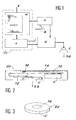
- the device shown in FIG. 1 comprises: a transducer or coupler C, which has the purpose of transmitting the sequences of acoustic signals SQ.
- An acoustic coupler can consist of a small metal cup in the center of which a piezoelectric transducer is stuck. You can also use a small speaker.
- the device also includes a generator G capable of generating sequences of electrical signals capable of controlling the transducer C.
- a generator G capable of generating sequences of electrical signals capable of controlling the transducer C.
- an electrical signal generator in the telephone band such as the PCD 3311 circuit which produces signals allowing to emit tones conforming to code Q23 of CCITT
- the electronic circuit CC for controlling the generator G comprises a logic microstructure L capable of supplying the generator G with a sequence of data developed from information stored in a memory M.
- This microstructure L can be made up of any logic circuit such as a microprocessor.
- microcontrollers such as the TCM 8305 which has not only the capacity to transmit telephone signals, but also that of fetching sequences of signals in an external memory.
- the microstructure L and the generator G and possibly the memory M are then combined on the same chip, in silicon for example.
- the device also comprises one or more batteries capable of supplying the means M, G, L and C.
- the user has a control means B acting by pressure or by contact and which is capable of triggering the elaboration of one of the sequences from the data stored in the memory M.
- the memory M is moreover provided with an input means E for the information, prior to the commissioning of the device.
- the device Under the control of means B, the device emits a sequence of signals but it never emits the same sequence of signals from one time to another.
- An embodiment intended for use on the telephone network can consist, according to the diagram of FIG. 2, of a printed circuit 10 carrying on its lower face the battery P and the integrated circuits 12 necessary for operation. On its upper face the circuit carries a push button 14 for the control as well as contacts 16 for providing the implementation data to the logic circuits.
- the different sequences of data to be transmitted are stored in an additional memory such as an EPROM or a static RAM and a different recording is read on each command.
- an additional memory such as an EPROM or a static RAM
- the number of sequences that a device can transmit is therefore limited by the size of the memory since a recording is only read once.
- a first device can send the numbers from 1 to 1000
- a second device can send the numbers from 1001 to 2000
- the first device will emit the number 1, at the second the number 2, etc ...
- We will have thus created a family of devices, which, provided that we do not use them more than 1000 times each, can be easily differentiated from each other and will never emit the same frequency.
- the sequences SQ emitted by the device according to the invention have the characteristics making it possible to associate an account number with each device.
- a variant of the invention consists in fact in producing devices which transmit on each command different sequences, but one or more parts of the transmitted sequence of which are constant.
- One solution is to read the same sequence in the memory always before searching for the variable sequence in the table. If the fixed sequence represents the expiration date, we have the means to transmit this expiration date.
- Another variant of the invention consists in calculating a sequence, on the basis of a function of the number of times the button has been pressed. This correspondence between sequence and number must be one-to-one and vary the maximum number of signals in the sequence.
- An encryption algorithm such as DES ("Data Encryption Standard") meets these conditions.
- the key used to operate DES can be different in each device. We then use the fixed part of the message sent to find the reference of this key in a table located in the central computer receiving the message. We then say that we use encryption with diversified key.
Landscapes
- Business, Economics & Management (AREA)
- Accounting & Taxation (AREA)
- Physics & Mathematics (AREA)
- General Physics & Mathematics (AREA)
- Finance (AREA)
- Engineering & Computer Science (AREA)
- Strategic Management (AREA)
- General Business, Economics & Management (AREA)
- Theoretical Computer Science (AREA)
- Computer Networks & Wireless Communication (AREA)
- Telephone Function (AREA)
- Selective Calling Equipment (AREA)
- Mobile Radio Communication Systems (AREA)
- Control Of Vending Devices And Auxiliary Devices For Vending Devices (AREA)
- Meter Arrangements (AREA)
- Telephonic Communication Services (AREA)
- Radar Systems Or Details Thereof (AREA)
- Credit Cards Or The Like (AREA)
- Measurement Of Velocity Or Position Using Acoustic Or Ultrasonic Waves (AREA)
- Measurement And Recording Of Electrical Phenomena And Electrical Characteristics Of The Living Body (AREA)
- Arrangements For Transmission Of Measured Signals (AREA)
Abstract
Description
La présente invention a pour objet un dispositif émetteur de signaux acoustiques destiné à être utilisé comme moyen de paiement électronique de services par l'intermédiaire du téléphone.The present invention relates to a device for transmitting acoustic signals intended to be used as a means of electronic payment for services via the telephone.
On connaît ces dispositifs émetteurs de signaux acoustiques du genre calculette aptes à stocker et à émettre des numéros de téléphone. Ces dispositifs offrent la possibilité à l'utilisateur d'entrer des séquences de nombres sur un clavier et de les restituer par couplage acoustique sur le réseau téléphonique. L'utilisateur peut ainsi réémettre de façon répétitive une séquence de signaux acoustiques tels qu'un code secret, lui permettant de consulter, sur un serveur vocal, son compte en banque ou sa boîte à lettres. Le code nécessaire à la transaction étant toujours le même, une personne mal intentionnée peut, en se branchant sur la ligne, enregistrer à l'aide d'un magnétophone les tonalités émises et les réémettre ensuite pour son usage personnel.These devices are known as transmitters of acoustic signals of the calculator type capable of storing and transmitting telephone numbers. These devices offer the user the possibility of entering sequences of numbers on a keyboard and of reproducing them by acoustic coupling on the telephone network. The user can thus repeatedly repeat a sequence of acoustic signals such as a secret code, allowing him to consult, on a voice server, his bank account or his mailbox. Since the code required for the transaction is always the same, a malicious person can, by plugging into the line, record the tones emitted using a tape recorder and then re-emit them for his personal use.
Pour remédier à cet inconvénient, d'autres dispositifs ont été imaginés, notamment pour l'accès à un ordinateur par la voie téléphonique, dans lesquels la séquence émise change à chaque émission. Ainsi, le document US-A-4 601 011 prévoit de changer la séquence émise grâce à un compteur dont le contenu est incrémenté à chaque utilisation. Le contenu de ce compteur détermine en partie le message numérique envoyé. Le dispositif comporte un clavier d'introduction d'un code personnel, ce qui le rend encombrant et augmente son prix. Mais il est indispensable dans l'application décrite, en particulier pour permettre le déchiffrement de la séquence émise.To overcome this drawback, other devices have been devised, in particular for accessing a computer by telephone, in which the sequence transmitted changes with each transmission. Thus, document US-A-4 601 011 provides for changing the sequence transmitted by means of a counter whose content is incremented with each use. The content of this counter partly determines the digital message sent. The device includes an introduction keyboard a personal code, which makes it bulky and increases its price. But it is essential in the application described, in particular to allow the decryption of the transmitted sequence.
Bien que n'étant pas à prendre en considération pour l'appréciation de l'activité inventive de l'invention qui va être décrite, puisque non encore publiée, la demande de brevet français EN 90 04367 du 5 avril 1990 au nom du Demandeur (demande américaine correspondante SN 07/680,851) peut être évoquée ici, pour une meilleure compréhension de la présente invention, car cette demande décrit un dispositif électronique qui émet lui aussi des séquences changeant dans le temps. Le dispositif décrit dans cette demande antérieure comprend un émetteur acoustique relié à un générateur de commande apte à engendrer des tonalités tombant dans la bande téléphonique, une mémoire contenant un premier code d'identification et un second code ou clé de service liée au système téléphonique dans lequel le dispositif est utilisé, une horloge donnant la date et déterminant l'instant de péremption du dispositif. Un circuit électronique et logique est relié à la mémoire et à l'horloge et commande le générateur, ce circuit étant apte à former un message constitué par une suite de nombres qui dépend du premier code, de la clé, et de la date indiquée par l'horloge. Chaque nombre de cette suite commande le générateur pour l'émission d'une tonalité particulière par l'émetteur acoustique. Le dispositif comprend encore une pile apte à alimenter en permanence l'horloge, la mémoire et le circuit électronique, et un interrupteur commandé manuellement apte à mettre en service le générateur pour produire l'émission de la séquence de tonalités.Although not to be taken into consideration for the assessment of the inventive step of the invention which will be described, since not yet published, the French patent application EN 90 04367 of April 5, 1990 in the name of the Applicant ( corresponding American application SN 07 / 680,851) can be mentioned here, for a better understanding of the present invention, since this application describes an electronic device which also transmits sequences changing over time. The device described in this previous application comprises an acoustic transmitter connected to a command generator capable of generating tones falling in the telephone band, a memory containing a first identification code and a second code or service key linked to the telephone system in which the device is used, a clock giving the date and determining the expiration time of the device. An electronic and logic circuit is connected to the memory and to the clock and controls the generator, this circuit being able to form a message constituted by a series of numbers which depends on the first code, on the key, and on the date indicated by the clock. Each number in this sequence controls the generator for the emission of a particular tone by the acoustic transmitter. The device also comprises a battery capable of permanently supplying the clock, the memory and the electronic circuit, and a manually controlled switch able to activate the generator to produce the emission of the sequence of tones.
Dans ce dispositif, l'horloge a pour but, en particulier, de changer régulièrement la séquence émise, de façon qu'une même séquence ne puisse être utilisée trop longtemps. Ce système présente dans certaines applications deux inconvénients : d'une part, celui de consommer en permanence de l'énergie pour alimenter l'horloge et, d'autre part, celui d'émettre la même séquence pendant la période de temps prise comme unité ou, si l'on supprime cette possibilité, d'imposer la neutralisation des émissions pendant cette période.In this device, the clock aims, in particular, to regularly change the sequence transmitted, so that the same sequence cannot be used for too long. This system has two drawbacks in certain applications: on the one hand, that of constantly consuming energy to power the clock and, on the other hand, that of transmitting the same sequence during the period of time taken as a unit or, if this possibility is removed, to impose neutralization of emissions during this period.
On connaît également des dispositifs de type porte-monnaie ou porte-jetons électroniques reposant sur la carte à mémoire. Mais ces dispositifs nécessitent l'emploi d'un lecteur de carte spécialisé et ils sont donc d'un emploi peu aisé.There are also known devices of the purse or electronic token type based on the memory card. However, these devices require the use of a specialized card reader and are therefore not very easy to use.
On connaît encore par le document EP-A-0 244 332 des dispositifs fonctionnant dans l'infra-rouge et destinés à la commande des serrures des voitures. Ces dispositifs comportent encore un clavier.Also known from document EP-A-0 244 332 are devices operating in the infrared and intended for controlling the locks of cars. These devices also include a keyboard.
En dehors des dispositifs dont l'émetteur comporte un clavier permettant d'entrer des données de personnalisation, on connaît encore deux systèmes à commande unique qui sont décrits dans les documents EP-A-0 385 070 et US-A-4 928 098. Le premier consiste à émettre de façon cyclique une suite de codes stockés dans une table, mais la répétition de ces codes, au bout d'un certain temps, réduit considérablement la sécurité du système. Le deuxième est plus complexe puisqu'il consiste à transmettre une partie fixe et un mot chiffré, le récepteur vérifiant la concordance entre la partie fixe et le mot chiffré. Ce dispositif, qui n'a aucune vocation monétaire ou téléphonique, peut être réinitialisé par l'utilisateur par déconnexion de la pile. Dans ce cas, il réémet les mêmes séquences de signaux, sauf dans la variante décrite dans laquelle l'utilisateur dispose d'interrupteurs lui permettant de reprogrammer partiellement le mot fixe.Apart from the devices, the transmitter of which includes a keyboard for entering personalization data, there are also two known single control systems which are described in documents EP-A-0 385 070 and US-A-4 928 098. The first consists in transmitting cyclically a series of codes stored in a table, but the repetition of these codes, after a certain time, considerably reduces the security of the system. The second is more complex since it consists in transmitting a fixed part and an encrypted word, the receiver checking the agreement between the fixed part and the encrypted word. This device, which has no monetary or telephone purpose, can be reset by the user by disconnecting the battery. In this case, it retransmits the same signal sequences, except in the variant described in which the user has switches allowing him to partially reprogram the fixed word.
La présente invention a justement pour but de remédier à ces divers inconvénients des dispositifs antérieurs. A cette fin, elle propose un dispositif émetteur d'une très grande simplicité de structure et d'emploi et qui est apte à engendrer des séquences différentes d'une émission à l'autre.The object of the present invention is precisely to remedy these various drawbacks of the prior devices. To this end, it offers a transmitter device which is very simple in structure and use and which is capable of generating different sequences from one program to another.
De façon précise, la présente invention a pour objet un dispositif émetteur de séquences de signaux, comprenant :
- un transducteur apte à émettre des signaux sous la commande de signaux électriques,
- un générateur de commande apte à engendrer des séquences de signaux électriques appliqués au transducteur,
- un circuit électronique de commande du générateur, comprenant notamment une mémoire où sont préenregistrées des données servant à définir des séquences de signaux et une unité logique apte à former ces séquences,
- un moyen d'alimentation du circuit électronique et du générateur,
- un moyen de commande accessible par l'utilisateur du dispositif, ce moyen de commande étant apte à déclencher le fonctionnement du circuit électronique pour la commande du générateur et l'émission par le transducteur d'une séquence de signaux,
- le circuit électronique de commande du générateur est apte à engendrer des séquences de signaux électriques différentes à chaque action sur le moyen de commande, ces séquences étant différentes pour différents dispositifs, le dispositif émettant ainsi des séquences de signaux différentes les unes des autres à chaque action sur le moyen de commande, et les séquences émises par un dispositif étant différentes des séquences émises par tout autre dispositif analogue,
- le transducteur émet des signaux acoustiques ayant une fréquence compatible avec la bande téléphonique et dont la puissance est adaptée à leur transmission sur le réseau téléphonique par l'intermédiaire du microphone d'un combiné téléphonique,
- la mémoire est pourvue d'une liaison électrique pour l'introduction de données servant à la détermination des séquences de signaux préalablement à la livraison du dispositif à l'utilisateur, et
- le circuit électronique est apte à définir des séquences comprenant une partie fixe et une partie variable qui change à chaque action sur le moyen de commande.
- a transducer capable of transmitting signals under the control of electrical signals,
- a control generator capable of generating sequences of electrical signals applied to the transducer,
- an electronic generator control circuit, comprising in particular a memory in which data are pre-recorded used to define signal sequences and a logic unit capable of forming these sequences,
- a means of supplying the electronic circuit and the generator,
- a control means accessible by the user of the device, this control means being capable of triggering the operation of the electronic circuit for the control of the generator and the emission by the transducer of a sequence of signals,
- the electronic control circuit of the generator is able to generate different electrical signal sequences on each action on the control means, these sequences being different for different devices, the device thus emitting different signal sequences from each other at each action on the control means, and the sequences transmitted by a device being different from the sequences transmitted by any other similar device,
- the transducer emits acoustic signals having a frequency compatible with the telephone band and the power of which is adapted to their transmission over the telephone network via the microphone of a telephone handset,
- the memory is provided with an electrical connection for the input of data used for determining the signal sequences prior to the delivery of the device to the user, and
- the electronic circuit is able to define sequences comprising a fixed part and a variable part which changes with each action on the control means.
Les séquences de signaux électriques (ou tout au moins leur partie variable) peuvent être calculées à chaque émission par un algorithme qui est incrémenté à chaque nouvelle commande. L'algorithme peut mettre en oeuvre des procédés à clés diversifiées, chaque dispositif étant alors pourvu d'une clé diversifiée.The electrical signal sequences (or at least their variable part) can be calculated on each transmission by an algorithm which is incremented with each new command. The algorithm can implement diversified key methods, each device then being provided with a diversified key.
Mais ces séquences, (ou tout au moins leur partie variable) peuvent être stockées dans une mémoire, chaque enregistrement correspondant à une action sur le dispositif de commande, ne pouvant être lu qu'une fois.But these sequences, (or at least their variable part) can be stored in a memory, each record corresponding to an action on the control device, can only be read once.
- la figure 1 montre le schéma synoptique du dispositif ;Figure 1 shows the block diagram of the device;
- la figure 2 représente une vue schématique en coupe du dispositif ;Figure 2 shows a schematic sectional view of the device;
- la figure 3 montre l'allure générale du dispositif dans le cas d'une réalisation sous forme de jeton.Figure 3 shows the general appearance of the device in the case of an embodiment in the form of a token.
Le dispositif représenté sur la figure 1 comprend : un transducteur ou coupleur C, qui a pour but d'émettre les séquences de signaux acoustiques SQ. Un coupleur acoustique peut être constitué d'une petite coupelle en métal au centre de laquelle est collé un transducteur piézoélectrique. On peut aussi utiliser un petit haut-parleur.The device shown in FIG. 1 comprises: a transducer or coupler C, which has the purpose of transmitting the sequences of acoustic signals SQ. An acoustic coupler can consist of a small metal cup in the center of which a piezoelectric transducer is stuck. You can also use a small speaker.
Le dispositif comprend encore un générateur G apte à engendrer des séquences de signaux électriques aptes à commander le transducteur C. A titre d'exemple, on peut utiliser un générateur de signaux électriques dans la bande téléphonique tel que le circuit PCD 3311 qui produit des signaux permettant d'émettre des tonalités conformes au code Q23 du C.C.I.T.T.The device also includes a generator G capable of generating sequences of electrical signals capable of controlling the transducer C. For example, one can use an electrical signal generator in the telephone band such as the PCD 3311 circuit which produces signals allowing to emit tones conforming to code Q23 of CCITT
Le circuit électronique CC de commande du générateur G comprend une microstructure logique L capable de fournir au générateur G une séquence de données élaborée à partir d'informations stockées dans une mémoire M. Cette microstructure L peut être constituée de tout circuit logique tel qu'un microprocesseur. Eventuellement, il est possible d'utiliser des microcontrôleurs comme le TCM 8305 qui possède non seulement la capacité d'émettre des signaux téléphoniques, mais aussi celle d'aller chercher des séquences de signaux dans une mémoire extérieure. La microstructure L et le générateur G et éventuellement la mémoire M sont alors confondus sur une même puce, en silicium par exemple.The electronic circuit CC for controlling the generator G comprises a logic microstructure L capable of supplying the generator G with a sequence of data developed from information stored in a memory M. This microstructure L can be made up of any logic circuit such as a microprocessor. Optionally, it is possible to use microcontrollers such as the TCM 8305 which has not only the capacity to transmit telephone signals, but also that of fetching sequences of signals in an external memory. The microstructure L and the generator G and possibly the memory M are then combined on the same chip, in silicon for example.
Le dispositif comprend encore une ou plusieurs piles aptes à alimenter les moyens M, G, L et C.The device also comprises one or more batteries capable of supplying the means M, G, L and C.
L'utilisateur dispose d'un moyen de commande B agissant par pression ou par contact et qui est apte à déclencher l'élaboration d'une des séquences à partir des données stockées dans la mémoire M.The user has a control means B acting by pressure or by contact and which is capable of triggering the elaboration of one of the sequences from the data stored in the memory M.
La mémoire M est par ailleurs pourvue d'un moyen d'entrée E des informations, préalablement à la mise en service du dispositif.The memory M is moreover provided with an input means E for the information, prior to the commissioning of the device.
Sous la commande du moyen B, le dispositif émet une séquence de signaux mais il n'émet jamais, d'une fois sur l'autre, la même séquence de signaux.Under the control of means B, the device emits a sequence of signals but it never emits the same sequence of signals from one time to another.
Une réalisation destinée à être utilisée sur le réseau téléphonique peut être constituée, selon le schéma de la figure 2, d'un circuit imprimé 10 portant sur sa face inférieure la pile P et les circuits intégrés 12 nécessaires au fonctionnement. Sur sa face supérieure le circuit porte un bouton poussoir 14 pour la commande ainsi que des contacts 16 permettant de fournir les données de mise en oeuvre aux circuits logiques.An embodiment intended for use on the telephone network can consist, according to the diagram of FIG. 2, of a printed
Selon un mode de réalisation de l'invention, on stocke les différentes séquences de données à émettre dans une mémoire annexe telle qu'une EPROM ou une RAM statique et on vient lire un enregistrement différent à chaque commande. Dans ce mode de réalisation, le nombre de séquences que peut émettre un dispositif est donc limité par la taille de la mémoire puisqu'on ne lit un enregistrement qu'une fois.According to one embodiment of the invention, the different sequences of data to be transmitted are stored in an additional memory such as an EPROM or a static RAM and a different recording is read on each command. In this embodiment, the number of sequences that a device can transmit is therefore limited by the size of the memory since a recording is only read once.
Une autre caractéristique de l'invention est que des dispositifs différents émettent des séquences différentes. A titre d'exemple tout à fait trivial, un premier dispositif pourra émettre les nombres de 1 à 1000, un deuxième dispositif pourra émettre les nombres de 1001 à 2000, un troisième de 2001 à 3000 et ainsi de suite. A la première commande, le premier dispositif émettra le chiffre 1, à la deuxième le chiffre 2, etc... On aura ainsi créé une famille de dispositifs, qui, à condition de ne pas les utiliser plus de 1000 fois chacun, pourront être facilement différenciés les uns des autres et n'émettront jamais la même fréquence.Another characteristic of the invention is that different devices transmit different sequences. As a very trivial example, a first device can send the numbers from 1 to 1000, a second device can send the numbers from 1001 to 2000, a third from 2001 to 3000 and so on. At the first command, the first device will emit the number 1, at the second the number 2, etc ... We will have thus created a family of devices, which, provided that we do not use them more than 1000 times each, can be easily differentiated from each other and will never emit the same frequency.
Il est évident qu'un choix judicieux des séquences émises par chaque dispositif permet d'éviter qu'un individu puisse deviner les séquences qui restent à émettre. Il est par exemple possible de brasser aléatoirement, lors de la fabrication ou de la mise en service des dispositifs, les séquences devant être émises en notant la liste et éventuellement l'ordre des séquences inscrites dans chaque dispositif.It is obvious that a judicious choice of the sequences emitted by each device makes it possible to avoid that an individual can guess the sequences which remain to be emitted. It is for example possible to randomly mix, during the manufacture or the commissioning of the devices, the sequences to be transmitted by noting the list and possibly the order of the sequences entered in each device.
Si le dispositif de l'invention est utilisé dans l'application décrite dans la demande de brevet français n° 90 0468 déjà citée, les séquences SQ émises par le dispositif selon l'invention présentent les caractéristiques permettant d'associer à chaque dispositif un numéro de compte. On peut alors associer au dispositif, soit une valeur faciale monétaire, soit un nombre d'unités de compte et le faire évoluer au fil des transactions comme décrit dans la demande précitée. On peut également associer au dispositif une date de péremption qui peut être soit stockée dans l'ordinateur de gestion des comptes avec la liste des séquences de chaque dispositif, soit transmise par le dispositif avec chaque séquence.If the device of the invention is used in the application described in the French patent application No. 90 0468 already cited, the sequences SQ emitted by the device according to the invention have the characteristics making it possible to associate an account number with each device. One can then associate with the device, either a monetary face value, or a number of units of account and make it evolve with the wire of the transactions as described in the aforementioned request. We can also associate with the device an expiration date which can either be stored in the account management computer with the list of sequences of each device, or transmitted by the device with each sequence.
Une variante de l'invention consiste en effet à réaliser des dispositifs qui transmettent à chaque commande des séquences différentes, mais dont une ou plusieurs parties de la séquence émise sont constantes. Une solution consiste à aller lire dans la mémoire toujours la même séquence avant d'aller chercher la séquence variable dans la table. Si la séquence fixe représente la date de péremption, on a ainsi le moyen de transmettre cette date de péremption.A variant of the invention consists in fact in producing devices which transmit on each command different sequences, but one or more parts of the transmitted sequence of which are constant. One solution is to read the same sequence in the memory always before searching for the variable sequence in the table. If the fixed sequence represents the expiration date, we have the means to transmit this expiration date.
Une autre variante de l'invention consiste à calculer une séquence, à partir d'une fonction du nombre de fois où l'on a appuyé sur la commande. Cette correspondance entre séquence et nombre doit être biunivoque et faire varier le maximum de signaux de la séquence. Un algorithme de chiffrement tel que le DES ("Data Encryption Standard") répond à ces conditions.Another variant of the invention consists in calculating a sequence, on the basis of a function of the number of times the button has been pressed. This correspondence between sequence and number must be one-to-one and vary the maximum number of signals in the sequence. An encryption algorithm such as DES ("Data Encryption Standard") meets these conditions.
La clé utilisée pour faire fonctionner le DES peut être différente dans chaque dispositif. On utilise alors la partie fixe du message émis pour retrouver dans une table située dans l'ordinateur central recevant le message, la référence de cette clé. On dit alors que l'on utilise un chiffrement à clé diversifiée.The key used to operate DES can be different in each device. We then use the fixed part of the message sent to find the reference of this key in a table located in the central computer receiving the message. We then say that we use encryption with diversified key.
Lorsque le dispositif est utilisé dans un système de paiement, il est commode d'indiquer sur celui-ci sa valeur, avant toute utilisation, en unités monétaires ou de service. Bien que cette valeur évolue au fur et à mesure des utilisations, cette solution est admise pour les télécartes.When the device is used in a payment system, it is convenient to indicate thereon its value, before any use, in monetary or service units. Although this value changes over time, this solution is accepted for calling cards.
Dans la mesure où le système comporte une pile et n'est pas rechargeable puisque ses données s'effacent lorsque l'on enlève la pile, on peut inscrire dessus une date de péremption.Insofar as the system has a battery and is not rechargeable since its data is erased when the battery is removed, an expiration date can be written on it.
Claims (7)
Applications Claiming Priority (2)
| Application Number | Priority Date | Filing Date | Title |
|---|---|---|---|
| FR9012804A FR2668280A1 (en) | 1990-10-17 | 1990-10-17 | SIGNAL SEQUENCE TRANSMITTER DEVICE. |
| FR9012804 | 1990-10-17 |
Publications (3)
| Publication Number | Publication Date |
|---|---|
| EP0481879A1 true EP0481879A1 (en) | 1992-04-22 |
| EP0481879B1 EP0481879B1 (en) | 1996-08-21 |
| EP0481879B2 EP0481879B2 (en) | 2001-07-25 |
Family
ID=9401301
Family Applications (1)
| Application Number | Title | Priority Date | Filing Date |
|---|---|---|---|
| EP91402755A Expired - Lifetime EP0481879B2 (en) | 1990-10-17 | 1991-10-15 | Device for emitting signal sequences constituting a payment means |
Country Status (9)
| Country | Link |
|---|---|
| US (1) | US5216716A (en) |
| EP (1) | EP0481879B2 (en) |
| JP (1) | JP3198564B2 (en) |
| AT (1) | ATE141737T1 (en) |
| DE (1) | DE69121513T2 (en) |
| DK (1) | DK0481879T3 (en) |
| ES (1) | ES2092551T5 (en) |
| FR (1) | FR2668280A1 (en) |
| GR (1) | GR3021526T3 (en) |
Families Citing this family (9)
| Publication number | Priority date | Publication date | Assignee | Title |
|---|---|---|---|---|
| US7013393B1 (en) | 1999-12-21 | 2006-03-14 | Pierre Stevens | Universal intelligent card for secure access to system functions |
| EP1120752A1 (en) * | 2000-01-24 | 2001-08-01 | Franke & Co. Verwaltungs KG | System for controlling the entry or access authorisations |
| US7992067B1 (en) | 2001-11-09 | 2011-08-02 | Identita Technologies International SRL | Method of improving successful recognition of genuine acoustic authentication devices |
| US8266441B2 (en) * | 2005-04-22 | 2012-09-11 | Bank Of America Corporation | One-time password credit/debit card |
| CN101385402B (en) | 2006-02-13 | 2012-03-21 | 松下电器产业株式会社 | Circuit board and process for producing the same |
| US9251637B2 (en) * | 2006-11-15 | 2016-02-02 | Bank Of America Corporation | Method and apparatus for using at least a portion of a one-time password as a dynamic card verification value |
| US8002193B2 (en) | 2007-03-12 | 2011-08-23 | Visa U.S.A. Inc. | Payment card dynamically receiving power from external source |
| US10574650B2 (en) | 2017-05-17 | 2020-02-25 | Bank Of America Corporation | System for electronic authentication with live user determination |
| US10387632B2 (en) | 2017-05-17 | 2019-08-20 | Bank Of America Corporation | System for provisioning and allowing secure access to a virtual credential |
Citations (4)
| Publication number | Priority date | Publication date | Assignee | Title |
|---|---|---|---|---|
| US4601011A (en) * | 1981-12-30 | 1986-07-15 | Avigdor Grynberg | User authorization verification apparatus for computer systems including a central device and a plurality of pocket sized remote units |
| EP0244332A1 (en) * | 1986-04-22 | 1987-11-04 | René Soum | Remotely controlled system for relay-operated locking devices |
| US4928098A (en) * | 1984-03-30 | 1990-05-22 | Siemens Aktiengesellschaft | Method for code protection using an electronic key |
| EP0385070B1 (en) * | 1989-02-24 | 1994-02-16 | Daimler-Benz Aktiengesellschaft | Remote control system with a code transmitted by code words |
Family Cites Families (4)
| Publication number | Priority date | Publication date | Assignee | Title |
|---|---|---|---|---|
| US4998279A (en) * | 1984-11-30 | 1991-03-05 | Weiss Kenneth P | Method and apparatus for personal verification utilizing nonpredictable codes and biocharacteristics |
| US4736419A (en) * | 1984-12-24 | 1988-04-05 | American Telephone And Telegraph Company, At&T Bell Laboratories | Electronic lock system |
| IT1227401B (en) * | 1988-12-06 | 1991-04-08 | Delta Elettronica Spa | DEVICES FOR REMOTE TRANSMISSION OF SAFE CONTROLS |
| US5056137A (en) * | 1989-09-27 | 1991-10-08 | Sills Richard R | Method and apparatus for encoding and decoding signals |
-
1990
- 1990-10-17 FR FR9012804A patent/FR2668280A1/en active Granted
-
1991
- 1991-10-15 DK DK91402755.2T patent/DK0481879T3/en active
- 1991-10-15 ES ES91402755T patent/ES2092551T5/en not_active Expired - Lifetime
- 1991-10-15 EP EP91402755A patent/EP0481879B2/en not_active Expired - Lifetime
- 1991-10-15 DE DE69121513T patent/DE69121513T2/en not_active Expired - Lifetime
- 1991-10-15 AT AT91402755T patent/ATE141737T1/en not_active IP Right Cessation
- 1991-10-16 US US07/777,148 patent/US5216716A/en not_active Expired - Lifetime
- 1991-10-17 JP JP29652591A patent/JP3198564B2/en not_active Expired - Fee Related
-
1996
- 1996-10-31 GR GR960402889T patent/GR3021526T3/en unknown
Patent Citations (4)
| Publication number | Priority date | Publication date | Assignee | Title |
|---|---|---|---|---|
| US4601011A (en) * | 1981-12-30 | 1986-07-15 | Avigdor Grynberg | User authorization verification apparatus for computer systems including a central device and a plurality of pocket sized remote units |
| US4928098A (en) * | 1984-03-30 | 1990-05-22 | Siemens Aktiengesellschaft | Method for code protection using an electronic key |
| EP0244332A1 (en) * | 1986-04-22 | 1987-11-04 | René Soum | Remotely controlled system for relay-operated locking devices |
| EP0385070B1 (en) * | 1989-02-24 | 1994-02-16 | Daimler-Benz Aktiengesellschaft | Remote control system with a code transmitted by code words |
Also Published As
| Publication number | Publication date |
|---|---|
| DK0481879T3 (en) | 1996-11-25 |
| JPH0750726A (en) | 1995-02-21 |
| GR3021526T3 (en) | 1997-01-31 |
| EP0481879B2 (en) | 2001-07-25 |
| FR2668280B1 (en) | 1995-02-03 |
| US5216716A (en) | 1993-06-01 |
| DE69121513T2 (en) | 1997-03-06 |
| FR2668280A1 (en) | 1992-04-24 |
| EP0481879B1 (en) | 1996-08-21 |
| JP3198564B2 (en) | 2001-08-13 |
| DE69121513D1 (en) | 1996-09-26 |
| ATE141737T1 (en) | 1996-09-15 |
| ES2092551T3 (en) | 1996-12-01 |
| ES2092551T5 (en) | 2001-12-16 |
Similar Documents
| Publication | Publication Date | Title |
|---|---|---|
| EP1206856B1 (en) | Sound communication system between a portable unit and a communication terminal | |
| EP0765032A1 (en) | Remote control device for a video signal receiver | |
| WO2019115936A1 (en) | Device for storing digital keys for signing transactions on a blockchain | |
| EP0481879B1 (en) | Device for emitting signal sequences constituting a payment means | |
| FR3039687A1 (en) | METHOD FOR OPENING CONTROL OF A SINGLE-USE CODE LOCK | |
| EP0374012A1 (en) | Authentication apparatus for an interactive server | |
| EP1958132B1 (en) | Microprocessor and/or memory card provided with a display | |
| EP2118805B1 (en) | Portable authentication device | |
| FR2680263A1 (en) | Personal parking meter apparatus | |
| EP1250689A2 (en) | System and method for making secure data transmissions | |
| EP1216461A1 (en) | Method and system for secure and fast voice identification of a nomadic object emitting an audible signal | |
| FR2607340A1 (en) | Game-type device for placing plural parties in televideo communication | |
| FR2769446A1 (en) | Identification and authentication system for users of data network | |
| FR2732852A1 (en) | PORTABLE UNIDIRECTIONAL RADIO PASSENGER RECEIVER EQUIPPED WITH A TRANSMITTER OF CODED SOUND SIGNALS, AND IDENTIFICATION PROCESS USING THIS RECEIVER | |
| EP0817144B1 (en) | Method to control the use of a pager, pager functioning with this method and ic card for conditional access to a pager | |
| EP1490816B1 (en) | Interactive communication device | |
| EP1007170B1 (en) | Method and system for validating bets for a game, effected from an autonomous electronic housing | |
| FR2812105A1 (en) | Automatic secure access to different equipment and services, uses portable device containing microprocessor memory and communication components to access services | |
| FR2752963A1 (en) | Remote portable authentication device | |
| WO2020128203A1 (en) | Method and system for securing operations and associated user station | |
| FR2940731A1 (en) | Order i.e. meal ticket, management method for employee of enterprise, involves sending new order to payment device by short range wireless communication unit of mobile terminal, and verifying new order by payment device | |
| FR2865060A1 (en) | Non-volatile memory`s content modifying process for chip card, involves inputting short random code on keyboard of card reader to execute modification selected by card if transmitted code corresponds to initially transmitted code | |
| EP0838938A1 (en) | Method for payment of telephonic communications using an automatic dialer | |
| FR2849973A1 (en) | Secured transaction procedure for use in cyber cafe, involves personalizing calculation units e.g. PC, according to interaction among three different users | |
| EP0870279A1 (en) | Portable device for access to at least one service provided by a server |
Legal Events
| Date | Code | Title | Description |
|---|---|---|---|
| PUAI | Public reference made under article 153(3) epc to a published international application that has entered the european phase |
Free format text: ORIGINAL CODE: 0009012 |
|
| AK | Designated contracting states |
Kind code of ref document: A1 Designated state(s): AT BE CH DE DK ES FR GB GR IT LI LU NL SE |
|
| 17P | Request for examination filed |
Effective date: 19921001 |
|
| 17Q | First examination report despatched |
Effective date: 19941206 |
|
| GRAH | Despatch of communication of intention to grant a patent |
Free format text: ORIGINAL CODE: EPIDOS IGRA |
|
| GRAH | Despatch of communication of intention to grant a patent |
Free format text: ORIGINAL CODE: EPIDOS IGRA |
|
| GRAA | (expected) grant |
Free format text: ORIGINAL CODE: 0009210 |
|
| AK | Designated contracting states |
Kind code of ref document: B1 Designated state(s): AT BE CH DE DK ES FR GB GR IT LI LU NL SE AT BE CH DE DK ES FR GB GR IT LI LU NL SE |
|
| PG25 | Lapsed in a contracting state [announced via postgrant information from national office to epo] |
Ref country code: GB Free format text: LAPSE BECAUSE OF FAILURE TO SUBMIT A TRANSLATION OF THE DESCRIPTION OR TO PAY THE FEE WITHIN THE PRESCRIBED TIME-LIMIT Effective date: 19960821 Ref country code: AT Effective date: 19960821 Ref country code: NL Free format text: LAPSE BECAUSE OF FAILURE TO SUBMIT A TRANSLATION OF THE DESCRIPTION OR TO PAY THE FEE WITHIN THE PRESCRIBED TIME-LIMIT Effective date: 19960821 |
|
| REF | Corresponds to: |
Ref document number: 141737 Country of ref document: AT Date of ref document: 19960915 Kind code of ref document: T |
|
| REF | Corresponds to: |
Ref document number: 69121513 Country of ref document: DE Date of ref document: 19960926 |
|
| ITF | It: translation for a ep patent filed |
Owner name: PROPRIA PROTEZIONE PROPR. IND. |
|
| GBT | Gb: translation of ep patent filed (gb section 77(6)(a)/1977) |
Effective date: 19961022 |
|
| REG | Reference to a national code |
Ref country code: DK Ref legal event code: T3 |
|
| REG | Reference to a national code |
Ref country code: ES Ref legal event code: FG2A Ref document number: 2092551 Country of ref document: ES Kind code of ref document: T3 |
|
| REG | Reference to a national code |
Ref country code: GR Ref legal event code: FG4A Free format text: 3021526 |
|
| PLBQ | Unpublished change to opponent data |
Free format text: ORIGINAL CODE: EPIDOS OPPO |
|
| PLBI | Opposition filed |
Free format text: ORIGINAL CODE: 0009260 |
|
| PLBQ | Unpublished change to opponent data |
Free format text: ORIGINAL CODE: EPIDOS OPPO |
|
| PLBI | Opposition filed |
Free format text: ORIGINAL CODE: 0009260 |
|
| 26 | Opposition filed |
Opponent name: FRANCE TELECOM Effective date: 19970520 |
|
| 26 | Opposition filed |
Opponent name: GEMPLUS, AV. DU PIC DE BERTAGNE, PARC D'ACTIVITE D Effective date: 19970521 Opponent name: FINTEL Effective date: 19970521 Opponent name: FRANCE TELECOM Effective date: 19970520 |
|
| NLR1 | Nl: opposition has been filed with the epo |
Opponent name: GEMPLUS, AV. DU PIC DE BERTAGNE, PARC D'ACTIVITE D Opponent name: FINTEL Opponent name: FRANCE TELECOM |
|
| PLBF | Reply of patent proprietor to notice(s) of opposition |
Free format text: ORIGINAL CODE: EPIDOS OBSO |
|
| PLAB | Opposition data, opponent's data or that of the opponent's representative modified |
Free format text: ORIGINAL CODE: 0009299OPPO |
|
| R26 | Opposition filed (corrected) |
Opponent name: FRANCE TELECOM * 970521 FINTEL * 970521 GEMPLUS, G Effective date: 19970520 |
|
| PLBF | Reply of patent proprietor to notice(s) of opposition |
Free format text: ORIGINAL CODE: EPIDOS OBSO |
|
| NLR1 | Nl: opposition has been filed with the epo |
Opponent name: GEMPLUS, GEMENOS, ATT. MR. B. NONNENMACHER Opponent name: FRANCE TELECOM Opponent name: FINTEL |
|
| PLBF | Reply of patent proprietor to notice(s) of opposition |
Free format text: ORIGINAL CODE: EPIDOS OBSO |
|
| RAP2 | Party data changed (patent owner data changed or rights of a patent transferred) |
Owner name: SOCIETE D'EXPLOITATION DU JETON SECURISE- SEJS |
|
| RIN2 | Information on inventor provided after grant (corrected) |
Free format text: BERNARD, ALAIN |
|
| NLT2 | Nl: modifications (of names), taken from the european patent patent bulletin |
Owner name: SOCIETE D'EXPLOITATION DU JETON SECURISE- SEJS |
|
| PLBQ | Unpublished change to opponent data |
Free format text: ORIGINAL CODE: EPIDOS OPPO |
|
| PLBI | Opposition filed |
Free format text: ORIGINAL CODE: 0009260 |
|
| 26 | Opposition filed |
Opponent name: FNAC S.A. Effective date: 19990115 Opponent name: GEMPLUS, GEMENOS, ATT. MR. B. NONNENMACHER Effective date: 19970521 Opponent name: FINTEL Effective date: 19970521 Opponent name: FRANCE TELECOM Effective date: 19970520 |
|
| NLR1 | Nl: opposition has been filed with the epo |
Opponent name: GEMPLUS, GEMENOS, ATT. MR. B. NONNENMACHER Opponent name: FRANCE TELECOM Opponent name: FNAC S.A. Opponent name: FINTEL |
|
| PLAB | Opposition data, opponent's data or that of the opponent's representative modified |
Free format text: ORIGINAL CODE: 0009299OPPO |
|
| RDAH | Patent revoked |
Free format text: ORIGINAL CODE: EPIDOS REVO |
|
| R26 | Opposition filed (corrected) |
Opponent name: FRANCE TELECOM * 19970521 AUDIOSMARTCARD INTERNATI Effective date: 19970520 |
|
| APAC | Appeal dossier modified |
Free format text: ORIGINAL CODE: EPIDOS NOAPO |
|
| APAE | Appeal reference modified |
Free format text: ORIGINAL CODE: EPIDOS REFNO |
|
| NLR1 | Nl: opposition has been filed with the epo |
Opponent name: GEMPLUS, GEMENOS, ATT. MR. B. NONNENMACHER Opponent name: AUDIOSMARTCARD INTERNATIONAL S.A. Opponent name: FRANCE TELECOM |
|
| APAC | Appeal dossier modified |
Free format text: ORIGINAL CODE: EPIDOS NOAPO |
|
| PGFP | Annual fee paid to national office [announced via postgrant information from national office to epo] |
Ref country code: GR Payment date: 20001002 Year of fee payment: 10 |
|
| PGFP | Annual fee paid to national office [announced via postgrant information from national office to epo] |
Ref country code: LU Payment date: 20001006 Year of fee payment: 10 |
|
| PGFP | Annual fee paid to national office [announced via postgrant information from national office to epo] |
Ref country code: SE Payment date: 20001009 Year of fee payment: 10 |
|
| PGFP | Annual fee paid to national office [announced via postgrant information from national office to epo] |
Ref country code: DK Payment date: 20001012 Year of fee payment: 10 |
|
| PGFP | Annual fee paid to national office [announced via postgrant information from national office to epo] |
Ref country code: BE Payment date: 20001023 Year of fee payment: 10 |
|
| PGFP | Annual fee paid to national office [announced via postgrant information from national office to epo] |
Ref country code: NL Payment date: 20001026 Year of fee payment: 10 |
|
| PGFP | Annual fee paid to national office [announced via postgrant information from national office to epo] |
Ref country code: CH Payment date: 20001030 Year of fee payment: 10 Ref country code: DE Payment date: 20001030 Year of fee payment: 10 |
|
| PLBQ | Unpublished change to opponent data |
Free format text: ORIGINAL CODE: EPIDOS OPPO |
|
| PLBQ | Unpublished change to opponent data |
Free format text: ORIGINAL CODE: EPIDOS OPPO |
|
| PLAB | Opposition data, opponent's data or that of the opponent's representative modified |
Free format text: ORIGINAL CODE: 0009299OPPO |
|
| PLBQ | Unpublished change to opponent data |
Free format text: ORIGINAL CODE: EPIDOS OPPO |
|
| PLAB | Opposition data, opponent's data or that of the opponent's representative modified |
Free format text: ORIGINAL CODE: 0009299OPPO |
|
| R26 | Opposition filed (corrected) |
Opponent name: FRANCE TELECOM * 19970521 GEMPLUS, GEMENOS, ATT. M Effective date: 19970520 |
|
| R26 | Opposition filed (corrected) |
Opponent name: FRANCE TELECOM * 19970521 GEMPLUS, GEMENOS, ATT. M Effective date: 19970520 |
|
| APAC | Appeal dossier modified |
Free format text: ORIGINAL CODE: EPIDOS NOAPO |
|
| PLAW | Interlocutory decision in opposition |
Free format text: ORIGINAL CODE: EPIDOS IDOP |
|
| NLR1 | Nl: opposition has been filed with the epo |
Opponent name: FRANCE TELECOM Opponent name: GEMPLUS, GEMENOS, ATT. MR. B. NONNENMACHER |
|
| NLR1 | Nl: opposition has been filed with the epo |
Opponent name: GEMPLUS, GEMENOS, ATT. MR. B. NONNENMACHER Opponent name: FRANCE TELECOM |
|
| PUAH | Patent maintained in amended form |
Free format text: ORIGINAL CODE: 0009272 |
|
| STAA | Information on the status of an ep patent application or granted ep patent |
Free format text: STATUS: PATENT MAINTAINED AS AMENDED |
|
| 27A | Patent maintained in amended form |
Effective date: 20010725 |
|
| AK | Designated contracting states |
Kind code of ref document: B2 Designated state(s): AT BE CH DE DK ES FR GB GR IT LI LU NL SE |
|
| REG | Reference to a national code |
Ref country code: CH Ref legal event code: AEN Free format text: MAINTIEN DU BREVET DONT L'ETENDUE A ETE MODIFIEE |
|
| NLR2 | Nl: decision of opposition | ||
| PG25 | Lapsed in a contracting state [announced via postgrant information from national office to epo] |
Ref country code: LU Free format text: LAPSE BECAUSE OF NON-PAYMENT OF DUE FEES Effective date: 20011015 |
|
| PG25 | Lapsed in a contracting state [announced via postgrant information from national office to epo] |
Ref country code: SE Free format text: LAPSE BECAUSE OF NON-PAYMENT OF DUE FEES Effective date: 20011016 |
|
| PG25 | Lapsed in a contracting state [announced via postgrant information from national office to epo] |
Ref country code: DK Free format text: LAPSE BECAUSE OF FAILURE TO SUBMIT A TRANSLATION OF THE DESCRIPTION OR TO PAY THE FEE WITHIN THE PRESCRIBED TIME-LIMIT Effective date: 20011025 |
|
| PG25 | Lapsed in a contracting state [announced via postgrant information from national office to epo] |
Ref country code: DE Free format text: LAPSE BECAUSE OF FAILURE TO SUBMIT A TRANSLATION OF THE DESCRIPTION OR TO PAY THE FEE WITHIN THE PRESCRIBED TIME-LIMIT Effective date: 20011026 |
|
| PG25 | Lapsed in a contracting state [announced via postgrant information from national office to epo] |
Ref country code: CH Free format text: LAPSE BECAUSE OF NON-PAYMENT OF DUE FEES Effective date: 20011031 Ref country code: BE Free format text: LAPSE BECAUSE OF NON-PAYMENT OF DUE FEES Effective date: 20011031 Ref country code: GR Free format text: LAPSE BECAUSE OF NON-PAYMENT OF DUE FEES Effective date: 20011031 Ref country code: LI Free format text: LAPSE BECAUSE OF NON-PAYMENT OF DUE FEES Effective date: 20011031 |
|
| REG | Reference to a national code |
Ref country code: ES Ref legal event code: DC2A Kind code of ref document: T5 Effective date: 20011019 |
|
| REG | Reference to a national code |
Ref country code: GB Ref legal event code: IF02 |
|
| NLV1 | Nl: lapsed or annulled due to failure to fulfill the requirements of art. 29p and 29m of the patents act | ||
| REG | Reference to a national code |
Ref country code: GB Ref legal event code: 732E |
|
| BERE | Be: lapsed |
Owner name: BERNARD ALAIN Effective date: 20011031 |
|
| GBTA | Gb: translation of amended ep patent filed (gb section 77(6)(b)/1977) | ||
| EUG | Se: european patent has lapsed |
Ref document number: 91402755.2 |
|
| REG | Reference to a national code |
Ref country code: CH Ref legal event code: PL |
|
| REG | Reference to a national code |
Ref country code: FR Ref legal event code: TP |
|
| APAH | Appeal reference modified |
Free format text: ORIGINAL CODE: EPIDOSCREFNO |
|
| PG25 | Lapsed in a contracting state [announced via postgrant information from national office to epo] |
Ref country code: IT Free format text: LAPSE BECAUSE OF NON-PAYMENT OF DUE FEES;WARNING: LAPSES OF ITALIAN PATENTS WITH EFFECTIVE DATE BEFORE 2007 MAY HAVE OCCURRED AT ANY TIME BEFORE 2007. THE CORRECT EFFECTIVE DATE MAY BE DIFFERENT FROM THE ONE RECORDED. Effective date: 20051015 |
|
| REG | Reference to a national code |
Ref country code: GB Ref legal event code: 732E Free format text: REGISTERED BETWEEN 20101028 AND 20101103 |
|
| PGFP | Annual fee paid to national office [announced via postgrant information from national office to epo] |
Ref country code: FR Payment date: 20101104 Year of fee payment: 20 |
|
| PGFP | Annual fee paid to national office [announced via postgrant information from national office to epo] |
Ref country code: GB Payment date: 20101021 Year of fee payment: 20 |
|
| REG | Reference to a national code |
Ref country code: ES Ref legal event code: PC2A Owner name: NCRYPTONE Effective date: 20110324 |
|
| PGFP | Annual fee paid to national office [announced via postgrant information from national office to epo] |
Ref country code: ES Payment date: 20101021 Year of fee payment: 20 |
|
| REG | Reference to a national code |
Ref country code: GB Ref legal event code: PE20 Expiry date: 20111014 |
|
| REG | Reference to a national code |
Ref country code: ES Ref legal event code: FD2A Effective date: 20120424 |
|
| PG25 | Lapsed in a contracting state [announced via postgrant information from national office to epo] |
Ref country code: ES Free format text: LAPSE BECAUSE OF EXPIRATION OF PROTECTION Effective date: 20111016 |