EP0481692A2 - Multi-axis apparatus - Google Patents
Multi-axis apparatus Download PDFInfo
- Publication number
- EP0481692A2 EP0481692A2 EP91309375A EP91309375A EP0481692A2 EP 0481692 A2 EP0481692 A2 EP 0481692A2 EP 91309375 A EP91309375 A EP 91309375A EP 91309375 A EP91309375 A EP 91309375A EP 0481692 A2 EP0481692 A2 EP 0481692A2
- Authority
- EP
- European Patent Office
- Prior art keywords
- cylinder
- rotary
- reservoir
- piston
- rotary actuator
- Prior art date
- Legal status (The legal status is an assumption and is not a legal conclusion. Google has not performed a legal analysis and makes no representation as to the accuracy of the status listed.)
- Withdrawn
Links
Images


Classifications
-
- F—MECHANICAL ENGINEERING; LIGHTING; HEATING; WEAPONS; BLASTING
- F15—FLUID-PRESSURE ACTUATORS; HYDRAULICS OR PNEUMATICS IN GENERAL
- F15B—SYSTEMS ACTING BY MEANS OF FLUIDS IN GENERAL; FLUID-PRESSURE ACTUATORS, e.g. SERVOMOTORS; DETAILS OF FLUID-PRESSURE SYSTEMS, NOT OTHERWISE PROVIDED FOR
- F15B11/00—Servomotor systems without provision for follow-up action; Circuits therefor
- F15B11/06—Servomotor systems without provision for follow-up action; Circuits therefor involving features specific to the use of a compressible medium, e.g. air, steam
- F15B11/072—Combined pneumatic-hydraulic systems
- F15B11/076—Combined pneumatic-hydraulic systems with pneumatic drive or displacement and speed control or stopping by hydraulic braking
-
- F—MECHANICAL ENGINEERING; LIGHTING; HEATING; WEAPONS; BLASTING
- F15—FLUID-PRESSURE ACTUATORS; HYDRAULICS OR PNEUMATICS IN GENERAL
- F15B—SYSTEMS ACTING BY MEANS OF FLUIDS IN GENERAL; FLUID-PRESSURE ACTUATORS, e.g. SERVOMOTORS; DETAILS OF FLUID-PRESSURE SYSTEMS, NOT OTHERWISE PROVIDED FOR
- F15B15/00—Fluid-actuated devices for displacing a member from one position to another; Gearing associated therewith
- F15B15/02—Mechanical layout characterised by the means for converting the movement of the fluid-actuated element into movement of the finally-operated member
- F15B15/06—Mechanical layout characterised by the means for converting the movement of the fluid-actuated element into movement of the finally-operated member for mechanically converting rectilinear movement into non- rectilinear movement
- F15B15/063—Actuator having both linear and rotary output, i.e. dual action actuator
-
- F—MECHANICAL ENGINEERING; LIGHTING; HEATING; WEAPONS; BLASTING
- F15—FLUID-PRESSURE ACTUATORS; HYDRAULICS OR PNEUMATICS IN GENERAL
- F15B—SYSTEMS ACTING BY MEANS OF FLUIDS IN GENERAL; FLUID-PRESSURE ACTUATORS, e.g. SERVOMOTORS; DETAILS OF FLUID-PRESSURE SYSTEMS, NOT OTHERWISE PROVIDED FOR
- F15B2211/00—Circuits for servomotor systems
- F15B2211/20—Fluid pressure source, e.g. accumulator or variable axial piston pump
- F15B2211/21—Systems with pressure sources other than pumps, e.g. with a pyrotechnical charge
- F15B2211/212—Systems with pressure sources other than pumps, e.g. with a pyrotechnical charge the pressure sources being accumulators
-
- F—MECHANICAL ENGINEERING; LIGHTING; HEATING; WEAPONS; BLASTING
- F15—FLUID-PRESSURE ACTUATORS; HYDRAULICS OR PNEUMATICS IN GENERAL
- F15B—SYSTEMS ACTING BY MEANS OF FLUIDS IN GENERAL; FLUID-PRESSURE ACTUATORS, e.g. SERVOMOTORS; DETAILS OF FLUID-PRESSURE SYSTEMS, NOT OTHERWISE PROVIDED FOR
- F15B2211/00—Circuits for servomotor systems
- F15B2211/20—Fluid pressure source, e.g. accumulator or variable axial piston pump
- F15B2211/21—Systems with pressure sources other than pumps, e.g. with a pyrotechnical charge
- F15B2211/216—Systems with pressure sources other than pumps, e.g. with a pyrotechnical charge the pressure sources being pneumatic-to-hydraulic converters
-
- F—MECHANICAL ENGINEERING; LIGHTING; HEATING; WEAPONS; BLASTING
- F15—FLUID-PRESSURE ACTUATORS; HYDRAULICS OR PNEUMATICS IN GENERAL
- F15B—SYSTEMS ACTING BY MEANS OF FLUIDS IN GENERAL; FLUID-PRESSURE ACTUATORS, e.g. SERVOMOTORS; DETAILS OF FLUID-PRESSURE SYSTEMS, NOT OTHERWISE PROVIDED FOR
- F15B2211/00—Circuits for servomotor systems
- F15B2211/70—Output members, e.g. hydraulic motors or cylinders or control therefor
- F15B2211/71—Multiple output members, e.g. multiple hydraulic motors or cylinders
- F15B2211/7107—Multiple output members, e.g. multiple hydraulic motors or cylinders the output members being mechanically linked
-
- Y—GENERAL TAGGING OF NEW TECHNOLOGICAL DEVELOPMENTS; GENERAL TAGGING OF CROSS-SECTIONAL TECHNOLOGIES SPANNING OVER SEVERAL SECTIONS OF THE IPC; TECHNICAL SUBJECTS COVERED BY FORMER USPC CROSS-REFERENCE ART COLLECTIONS [XRACs] AND DIGESTS
- Y10—TECHNICAL SUBJECTS COVERED BY FORMER USPC
- Y10T—TECHNICAL SUBJECTS COVERED BY FORMER US CLASSIFICATION
- Y10T74/00—Machine element or mechanism
- Y10T74/20—Control lever and linkage systems
- Y10T74/20207—Multiple controlling elements for single controlled element
Definitions
- the present invention relates to a fluid-controlled apparatus for providing, simultaneously or separately, linear and rotary motion to a working member connected to the apparatus.
- Fluid driven systems have been previously devised for causing movement of a working member. It is common practice, for example, to manipulate a robot-like member by rotating it and/or moving it in a linear direction using pneumatic or hydraulic drive systems.
- An apparatus that uses pneumatics for rotary and linear motion is disclosed in U.S. Patent No. 3,815,479 to Thompson, issued June 11, 1974, and entitled "Compound Motion Fluid Actuator.”
- This apparatus includes a rack gear and a rotary gear for converting linear motion to rotary motion.
- This rotary actuator is driven by means of fluid pressure whereby linear movement of the rack gear causes the rotary gear to rotate.
- a power cylinder is attached to the rotary actuator and includes a hollow piston rod that extends beyond the end of the cylinder.
- a guide rod telescopically fits into the hollow piston rod for controlling rotation while permitting linear movement of the piston.
- the guide rod is interconnected to the rotary gear so that rotary motion of the rotary gear is imparted to the guide rod.
- the power cylinder can only be joined to the rotary actuator in one configuration, i.e., with the length of the power cylinder being substantially perpendicular to the length of the rotary actuator.
- this actuator requires these two major components to be connected in only one way due to the relationship between the hollow piston rod, the guide rod and the rotary gear.
- a further embodiment of an actuator apparatus that includes compound motion is apparently available through the Leen Company of Portland, Maine.
- This apparatus is exemplified in U.S. Design Patent No. D308,207 to Burke, May 29, 1990.
- a ball-spline sleeve is fixed to a pinion gear of the rotary actuator and a splined piston rod is provided in the ball-spline sleeve whereby the full stroke of the splined piston rod occurs with smooth, rolling linear movement.
- the pinion gear is provided at one end of the rotary actuator so that direct drive is achieved close to the work being done.
- the rotary actuator and the cylinder can only be connected in one way.
- a rotary actuator for converting linear motion to rotary motion
- the named assignee of the ′479 patent has devised an air/oil tandem actuator having two cylinders and two rack gears.
- a rotary gear is operably connected to each of the two rack gears whereby controlled movement of a first rack gear in a first linear direction causes the rotary gear to rotate in a clockwise direction, while the other of the two rack gears moves linearly in a second direction, opposite that of the first rack gear.
- counterclockwise rotation of the rotary gear is achieved by controlled movement of the second rack gear in the first direction.
- controlled movement of the second rack gear causes desired rotary movement of the rotary gear and accompanying linear movement of the first rack gear.
- this apparatus also includes hydraulic oil contained in each of the two tandem cylinders.
- the contained oil acts to smooth the movement of the rack gears and thus the rotary gear.
- a reservoir is in fluid communication with the oil contained in the tandem cylinders and serves to compensate for oil volume changes due to temperature variation and leakage thereof. This reservoir is spaced from the tandem cylinders and requires a header pressure. Because of the required header pressure, the output port formed in the reservoir must be positioned below the reservoir for proper operation.
- the present invention includes a rotary actuator assembly for converting linear motion to rotary motion.
- the rotary motion is coupled to a power cylinder having a piston assembly.
- the coupling of the rotary motion is achieved by means of a rotary table assembly.
- Use of the rotary table assembly enables the present invention to achieve a modular construction whereby the power cylinder is able to be selectively located relative to a rotatable shaft of the rotary actuator assembly in one of at least two positions. More particularly, the power cylinder can be located in one of two positions, with the two positions being substantially 90° apart. This is accomplished by means of the attachment between the power cylinder and a hub of the rotary table assembly.
- the rotary actuator assembly includes a rotary gear having a rotatable shaft connected thereto.
- the shaft is connected to a coupling device of the rotary table assembly.
- the coupling device is the device disclosed in the aforesaid U.S. Patent No. 4,202,644.
- the hub of the rotary table assembly has a bore which receives portions of the coupling device to connect the hub to the shaft driven by the rotary gear.
- Rotational motion of the hub is imparted to the power cylinder, which may be fastened to the hub by a plate interconnected to the power cylinder and the hub or by the end portion of the power cylinder itself. Consequently, rotational movement of the rotary gear causes rotation of the entire power cylinder, and not merely the piston assembly within the power cylinder.
- the attachment plate In a first position, the attachment plate is fastened to the power cylinder at one end of the length thereof for attachment to the hub.
- the longitudinal axis of the power cylinder is substantially coaxial to the longitudinal axis of the rotatable shaft of the rotary actuator assembly.
- the plate in a second position, is attached to the side or along the longitudinal extent of the power cylinder so that the second position is 90° from the first position.
- the rotary actuator assembly includes tandem cylinders that are pneumatically driven and which contain a fluid such as hydraulic oil to cause smooth rotation of the rotary gear.
- a hydraulic oil reservoir assembly is provided in communication with the two cylinders.
- the reservoir assembly includes a reservoir body, which is connected directly to the cylinders. Formed in the reservoir body are first and second cylinder passageways. The outlet ends of each of the two cylinder passageways are contiguously adjacent to the cylinders. Hydraulic oil is able to move directly between each cylinder and the reservoir body by means of the two cylinder passageways. Also formed in the reservoir body is a common passageway that interconnects the two cylinder passageways.
- the reservoir body also has a completely enclosed reservoir chamber for containing hydraulic oil.
- a reservoir port provides fluid communication between the chamber and the common passageway.
- First and second flow control cartridges are operably connected in the paths of the cylinder ports for use in controlling desired hydraulic oil movement during operation of the tandem cylinders. That is, when pressurized air is supplied to a first of the two tandem cylinders, the rack gear moves in response thereto and causes the hydraulic oil in the first cylinder to move in the cylinder port associated with that cylinder. Hydraulic oil moves past the flow control cartridge and into the common passageway and past the flow control cartridge associated with the second cylinder and into the cylinder passageway for the second cylinder. The oil then moves into the second cylinder causing its rack gear to move in a linear direction opposite to the movement of the first rack gear. To achieve opposite rotation of the rotary gear, pressurized air is applied to the other of the two cylinders and similar movement of hydraulic oil occurs.
- the reservoir includes an oil indicator assembly, which includes a plunger, a pull ring connected to the plunger and a spring surrounding the plunger.
- the plunger extends into the reservoir chamber, while the pull ring is connected to the plunger and is positioned exteriorly of the reservoir body.
- the pull ring rises or changes position to indicate the loss of the predetermined amount of oil so that one is aware that additional oil is required.
- An actuator is disclosed that achieves both rotary and linear motion of a power cylinder or like device.
- a rotary table assembly enables the invention to be modular in construction whereby the power cylinder can be readily attached/detached from the rotary actuator assembly. Because of this flexibility, the power cylinder can be arranged in two different positions. Consequently, depending upon the user's application, the power cylinder can be arranged relative to the rotary actuator assembly in the most advantageous configuration for achieving the desired work or objective. Unlike the prior art, there is no direct connection or internal communication between the rotary gear shaft and the piston of the power cylinder.
- tandem cylinders are utilized that incorporate hydraulic oil to achieve highly smooth, fully adjustable speed control of the rotary gear shaft.
- the reservoir is directly connected to the cylinder tandem whereby the outlet ends of the passageways carrying the oil are directly connected to the two cylinders.
- the apparatus can be mounted in any attitude with reduced concern that there will be any unwanted hydraulic oil backflow.
- the oil reservoir requires no air header pressure and is fully self-contained.
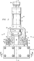
- a modular apparatus generally identified by the reference numeral 10 in which a power cylinder or like device is able to output, simultaneously or separately, linear motion and rotary motion.
- the apparatus 10 includes a rotary actuator assembly 12 that is air driven to convert linear motion to rotary motion.
- the rotary actuator assembly 12 is operably connected to a rotary table assembly 14 that includes a rotatable hub 16.
- the rotary motion, as indicated by a double headed arrow 17, of the rotary actuator assembly 12 is coupled to the hub 16.
- the apparatus 10 also includes a power cylinder 18 or like device that receives the outputted rotary motion 17.
- the power cylinder 18 includes a plate 20 that connects the power cylinder 18 to the hub 16 of the rotary table assembly 14. Although not shown, it is to be understood that the power cylinder 18 may be directly connected to the hub 16 by an end portion thereof. In one embodiment, the power cylinder 18 is, by itself, a non-rotating unit that is caused to rotate by the motion coupled to it through the hub 16.
- the power cylinder 18 is a conventional and well-known unit and includes a movable piston assembly having two piston rods and a piston.
- the piston assembly is adapted to move a tooling plate 24 linearly and, with respect to Figure 1, is able to move vertically up-and-down as indicated by a double headed arrow 26.
- Such vertical movement 26 is controlled using pressurized air (from a compressor 28) that passes through the cylinder wall 22 of the power cylinder 18 and creates a force on the piston therein for the desired movement 26 of the tooling plate 24 thereof.
- the rotary table assembly 14 includes a trantorque coupler 30 which provides interconnection between the rotary actuator assembly 12 and the hub 16.
- a rotary shaft 32 is connected at one end to the rotary actuator assembly 12 for rotational movement, as will be subsequently described in greater detail, and at another end to the trantoraue coupler 30.
- longitudinal axis 13 through the cylinder 18 is generally coaxial with a longitudinal axis 15 of the rotary shaft 32.
- the trantorque coupler 30, as best seen in Figure 3, comprises a segmented inner sleeve 34 and a segmented outer sleeve 36.
- the inner sleeve 34 has an inside diameter D slightly larger than the outside diameter d of the rotary shaft 32 to allow repositioning thereof along the linear axis of the shaft 32.
- a plurality of cutouts 38 and one cutout 40 are formed in the segmented inner sleeve 34.
- the cutouts 38 and 40 allow the inner sleeve 34 to contract when engaged by the outer sleeve 36 around the rotary shaft 32.
- the cutout 40 is the only cutout on the inner sleeve 34 which does not terminate along a line spaced inwardly from an end 42 of the inner sleeve 34.
- the outer sleeve 36 comprises a plurality of segments 44 each separated along lines 46.
- a hex nut 48 has an inner circumferential groove 50 for mating with an outer circumferential groove 52 and protrusion 54 on each of the segments 44.
- the hex nut 48 has internal threads 56 for receiving external threads 58 on the inner sleeve 34.
- the hex nut 48 has a width W which is slightly smaller than a diameter B of the hub 16.
- the outer sleeve 36 has an outer diameter b which is also slightly smaller than the diameter B of the hub 16.
- a split retainer ring 37 fits over the segments 44 of the outer sleeve 36 for contact with the bore 60 of the hub 16.
- the hub 16 has an inner circumferential glove 55 for receiving an "O"-ring 57 therein.
- the retainer ring 37 is positioned over the outer sleeve 36.
- the inner sleeve 34 is threaded slightly into the hex nut 48 which is already mated with the outer sleeve 36.
- the assembled coupler 30 is then inserted into the bore 60 of the hub 16 which is retained therein by the "O"-ring 57 until the entire rotary table assembly 14 is ready for attachment to the rotary shaft 32 of the rotary actuator assembly 12.
- the hex nut 48 is then tightened onto the inner sleeve 34 causing the inner sleeve 34 to contract around and tightly hold the rotary shaft 32 and causing the outer sleeve 36 to expand into the ring 37 and tightly hold the hub 16. Therefore, any rotational movement of the rotary shaft 32 will be transmitted to the hub 16 through the inner sleeve 34, the outer sleeve 36 and the retainer ring 37 of the trantorque coupler 30.
- the rotary table assembly 14 is attached to the rotary actuator assembly 12 by fasteners 62 such as, for example, bolts through a housing 64.
- a lock nut 66 is held within the housing 64 by a circumferential flange 68 which is a part of the housing 64.
- the hub 16 is threaded into the lock nut 66 until a shoulder 70 thereof contacts a thrust washer 74 on the flange 68.
- a thrust bearing 72 is inserted between the thrust washer 74 and another thrust washer 75.
- a thrust bearing 76 is installed between the lock nut 66 and the flange 68 with a thrust washer 78 and 79 positioned with the thrust bearing 76 therebetween.
- the bearings 72 and 76 and the washers 74, 75, 78 and 79 accept axial and radial loads applied to the rotary table assembly 14.
- a wear band 80 is installed between the hub 16 and the housing 64. Although not shown, it is to be understood that a grease fitting may be provided through the housing 64 to allow the application of a lubricant therein if necessary.
- the rotary actuator assembly 12 comprises a first cylinder 82 and a second cylinder 84.
- the cylinders 82 and 84 contain rack gears 86 and 88, respectively, for transmitting linear motion therefrom to a rotary gear 90.
- the rotary shaft 32 is fit to the rotary gear 90 by any appropriate method such as a key 92.
- the cylinders 82 and 84 have inlet/outlet ports 94 and 96, respectively, for the introduction and release of air.
- the first cylinder 82 has first piston 98 abutting and a second piston 100 affixed at opposite ends of the rack gear 86.
- the second cylinder 84 has first piston 102 abutting and a second piston 104 affixed at opposite ends of the rack gear 88.
- the pistons 98 through 104 are provided with appropriate seal rings 106 to form fluid tight chambers 108, 110, 112 and 114.
- the assembly 116 comprises a reservoir body 118 and first and second flow control cartridges 120 and 122.
- first and second cylinder passageways 124 and 126 are open at a first end 128 and 130, respectively, to the chambers 110 and 114.
- the first and second flow control cartridges 120 and 122 are Interconnecting the first and second flow cartridges 120 and 122 and the first and second cylinder passageways 124 and 126 is a common passageway 132.
- the control cartridges 120-122 are threaded into the reservoir body 118 in order to provide control of the hydraulic oil therein.
- the cartridges 120-122 contain a ball 134 and spring 136 for flow control, as is well known in the art.
- the spring 136 holds the ball 134 against a shoulder 138 to substantially prevent the flow of oil between the common passageway 132 and the first cylinder passageway 124.
- the ball 134 will press the spring 136 to allow oil to flow from the first cylinder passageway 124 into the common passageway 132.
- the cartridges 120 and 122 are adjustably inserted into the reservoir body 118 to provide passageways therearound.
- the cartridge 120 is inserted to provide a gap between a leading portion 138 thereof and a shoulder 140 of the first cylinder passageway 124.
- oil may flow between the leading edge 138 and the shoulder 140 in either direction. Therefore, it is possible to adjust rotational speed of the rotary gear 82 and thus the rotary shaft 32 by positioning the cartridges 120 and 122 appropriately.
- compressed air is forced through the inlet/outlet port 94 into the chamber 108.
- the piston 98 is forced in a direction indicated by an arrow 142.
- the rack gear 86 moves in the direction 142 and forces the piston 100 into the chamber 110.
- hydraulic oil therein is forced into the first cylinder passageway 124 past the cartridge 120 and into the common passageway 132. From the common passageway 132, the hydraulic oil bypasses the car-tridge 122 and enters the second cylinder passageway 126 and therefrom into the chamber 114.
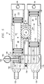
- FIG. 5 a cross-sectional view of the rotary actuator assembly along the same line 4-4 as Figure 4 with a cross-sectional view of the reservoir body 118 along the line 5-5 of Figure 2 is shown.
- an oil indicator assembly 148 and a reservoir chamber 150 are shown within the reservoir body 118.
- the reservoir chamber 150 further includes a reservoir port 152 for interconnection to the common passageway 132 (see Figure 4).
- the reservoir port 152 is controlled by a ball valve 154 which allows controlled flow from the chamber 150 to the common passageway 132 via a reservoir passageway 156 (see Figure 4).
- the port 152 is further provided with a bleed capability to allow hydraulic oil to pass from the common passageway 132 back into the chamber 150.
- the oil indicator assembly 148 comprises a plunger 158, a spring 160 and a pull ring 162.
- the pull ring 162 is pivotally attached to the plunger 158 to provide a signal that hydraulic oil in the chamber 150 is low, as will be subsequently described in greater detail.
- the plunger 158 is attached at an end opposite the ring 162 to a piston 164 having a piston ring 166 thereon.
- the plunger 158 passes through a plate 168 which is securely fastened to the reservoir body 118 by any appropriate method. Therefore, the spring 160 provides sufficient pressure against the piston 164 to appropriately pressurize the chamber 150 for passage of hydraulic oil therefrom.
- the reservoir chamber 150 is shown with the pull ring 162 in the low oil indicating condition.
- the plunger 158 is provided with a length appropriate to allow the piston 164 to reach a point slightly above the port 152.
- the pull ring 162 which was gradually pivoted from the vertical condition as shown in Figure 5 to a vertical position 180° therefrom in Figure 6.
- the rotary actuator assembly 12 may be oriented in any position without fear of hydraulic oil entering an air line as in the prior art.
- the flow control cartridges 120 and 122 allow a full control of the speed of rotation of the rotary gear 90.
- the speed at which hydraulic oil can flow is controlled or metered.
- the wider the gap therebetween the faster oil may flow thereby, and the faster the appropriate rack gear may move linearly and thus the faster the rotary gear 90 is rotated.
- the rotary actuator 12 provide a smooth rotation of the rotary gear 90, but it also provides a fully controllable rotation speed as well as the ability to be positioned in any orientation.
- FIG. 7 an alternative arrangement utilizing the rotary table assembly 14 of the present invention is illustrated.
- a power cylinder 172 is positioned on the rotatable hub 16 with its longitudinal axis 174 being substantially perpendicular to the longitudinal axis 15 of the rotary shaft 32. Therefore, the orientation of the cylinder 172 is approximately 90° from the orientation of the cylinder 18 as shown in Figure 1 and Figure 2.
- a plate 178 is fixed to a side of the cylinder 172 and to the hub 16.
- rotation of the rotary shaft 32 by the rotary actuator assembly 12 causes rotation of the cylinder 172 in a horizontal plane containing the axis 174 and being perpendicular to the plane of the paper of Figure 7.
- the orientation of a power cylinder may be varied between at least two positions.
- the first position as shown in Figures 1 and 2 places the longitudinal axis 13 of the power cylinder 18 generally coaxial with the longitudinal axis 15 of the rotary shaft 32.
- the second position approximately 90° from the first position, places the longitudinal axis 174 of the cylinder 172 generally perpendicular to the axis 15 of the shaft 32. Therefore, rotational movement may be imparted to a linear movement device in various configurations for more flexibility than in the prior art devices.
- a rotary actuator assembly 202 comprises a single pneumatic cylinder 204 as is known in the art. Air is provided to opposite ends of the cylinder 204 from a compressor 206 through inlet/outlet ports 208 and 210. As the cylinder 204 provides rotary motion as indicated by double headed arrow 212 to the rotary table assembly 14, the power cylinder 18 is similarly rotated. The apparatus 200 provides up-and-down motion in a direction 26 through action of the power cylinder 18 as previously described above. Although not shown, it is to be understood that the power cylinder 18 may be oriented 90° to the position shown in Figure 8 similarly to the cylinder 172 as described above with reference to Figure 7.
- FIG. 9 a cross-sectional view of the rotary actuator assembly 202 is shown.
- a piston 216 As air is forced into a first chamber 214 through the port 208, a piston 216 is forced in a direction indicated by an arrow 218.
- a rack gear 220 attached at one end to the piston 216 and at another end to a piston 222 is thus forced in the direction 218 pushing air from a chamber 224 out the port 210.
- the movement of the rack gear 220 in a direction 218 thus causes a rotational movement of a rotary gear 226 in a clockwise direction as indicated by an arrow 228 due to the meshing therebetween.
- the assembly 202 provides rotary motion in two directions to the rotary table assembly 14.
Landscapes
- Engineering & Computer Science (AREA)
- Physics & Mathematics (AREA)
- Fluid Mechanics (AREA)
- Mechanical Engineering (AREA)
- General Engineering & Computer Science (AREA)
- Chemical & Material Sciences (AREA)
- Analytical Chemistry (AREA)
- Actuator (AREA)
Abstract
An apparatus (10) for providing rotary and linear motions, either simultaneously or separately. The apparatus (10) includes a rotary table assembly (14) that interconnects a rotary actuator assembly (12) and a power cylinder (18) or a comparable device. The rotary table assembly (14) includes a rotatable hub (16) to which the power cylinder (18) is mounted. Rotation of the hub (16) cause rotary motion of the entire power cylinder (18). Because of the interconnection between the rotary actuator assembly (12) and the power cylinder (18) using a rotary table assembly (14), a modular construction is provided whereby the power cylinder (18) can be positioned both vertically and laterally, depending upon the application or intended use of the apparatus (10). In one preferred embodiment, the rotary actuator assembly (12) converts linear movement to rotary motion using hydraulic oil to provide a smooth, adjustable control of the rotary shaft (32) of the rotary actuator assembly (12). Hydraulic oil is located in a reservoir unit that is connected contiguously adjacent to the tandem cylinders (82 and 84) of the rotary actuator assembly (12).
Description
- The present invention relates to a fluid-controlled apparatus for providing, simultaneously or separately, linear and rotary motion to a working member connected to the apparatus.
- Fluid driven systems have been previously devised for causing movement of a working member. It is common practice, for example, to manipulate a robot-like member by rotating it and/or moving it in a linear direction using pneumatic or hydraulic drive systems. An apparatus that uses pneumatics for rotary and linear motion is disclosed in U.S. Patent No. 3,815,479 to Thompson, issued June 11, 1974, and entitled "Compound Motion Fluid Actuator." This apparatus includes a rack gear and a rotary gear for converting linear motion to rotary motion. This rotary actuator is driven by means of fluid pressure whereby linear movement of the rack gear causes the rotary gear to rotate. A power cylinder is attached to the rotary actuator and includes a hollow piston rod that extends beyond the end of the cylinder. A guide rod telescopically fits into the hollow piston rod for controlling rotation while permitting linear movement of the piston. The guide rod is interconnected to the rotary gear so that rotary motion of the rotary gear is imparted to the guide rod. Because of this construction, the power cylinder can only be joined to the rotary actuator in one configuration, i.e., with the length of the power cylinder being substantially perpendicular to the length of the rotary actuator. There is no modular relationship between the rotary actuator and the power cylinder in that this actuator requires these two major components to be connected in only one way due to the relationship between the hollow piston rod, the guide rod and the rotary gear.
- A further embodiment of an actuator apparatus that includes compound motion is apparently available through the Leen Company of Portland, Maine. This apparatus is exemplified in U.S. Design Patent No. D308,207 to Burke, May 29, 1990. With regard to the connection between the rotary actuator and the cylinder in this apparatus, a ball-spline sleeve is fixed to a pinion gear of the rotary actuator and a splined piston rod is provided in the ball-spline sleeve whereby the full stroke of the splined piston rod occurs with smooth, rolling linear movement. Additionally, the pinion gear is provided at one end of the rotary actuator so that direct drive is achieved close to the work being done. Like the compound actuator of the ′479 patent, the rotary actuator and the cylinder can only be connected in one way.
- With respect to mechanisms for coupling a rotating shaft to a machine element for imparting rotary motion to the element, such a mechanical unit is disclosed in U.S. Patent No. 4,202,644 to Soussloff, issued May 13, 1980, and entitled "Mounting Device." The disclosed device interconnects the cylindrical bore of the machine element to be rotated and a rotary shaft. The device has axially displacable sleeves that expand/contract to simultaneously grip the rotary shaft and the bore. The device further includes an internally threaded nut whereby rotation thereof allows axial displacement of the sleeves.
- With respect to another embodiment of a rotary actuator for converting linear motion to rotary motion, the named assignee of the ′479 patent has devised an air/oil tandem actuator having two cylinders and two rack gears. A rotary gear is operably connected to each of the two rack gears whereby controlled movement of a first rack gear in a first linear direction causes the rotary gear to rotate in a clockwise direction, while the other of the two rack gears moves linearly in a second direction, opposite that of the first rack gear. Conversely, counterclockwise rotation of the rotary gear is achieved by controlled movement of the second rack gear in the first direction. Relatedly, controlled movement of the second rack gear causes desired rotary movement of the rotary gear and accompanying linear movement of the first rack gear. Such controlled movement is accomplished using pressurized air. To provide smoother control of the rotary motion, this apparatus also includes hydraulic oil contained in each of the two tandem cylinders. When the racks are moved by pressurized air and there is accompanying rotary motion of the rotary gear, the contained oil acts to smooth the movement of the rack gears and thus the rotary gear. A reservoir is in fluid communication with the oil contained in the tandem cylinders and serves to compensate for oil volume changes due to temperature variation and leakage thereof. This reservoir is spaced from the tandem cylinders and requires a header pressure. Because of the required header pressure, the output port formed in the reservoir must be positioned below the reservoir for proper operation.
- The present invention includes a rotary actuator assembly for converting linear motion to rotary motion. The rotary motion is coupled to a power cylinder having a piston assembly. The coupling of the rotary motion is achieved by means of a rotary table assembly. Use of the rotary table assembly enables the present invention to achieve a modular construction whereby the power cylinder is able to be selectively located relative to a rotatable shaft of the rotary actuator assembly in one of at least two positions. More particularly, the power cylinder can be located in one of two positions, with the two positions being substantially 90° apart. This is accomplished by means of the attachment between the power cylinder and a hub of the rotary table assembly.
- The rotary actuator assembly includes a rotary gear having a rotatable shaft connected thereto. The shaft is connected to a coupling device of the rotary table assembly. In the preferred embodiment, the coupling device is the device disclosed in the aforesaid U.S. Patent No. 4,202,644.
- The hub of the rotary table assembly has a bore which receives portions of the coupling device to connect the hub to the shaft driven by the rotary gear. Rotational motion of the hub is imparted to the power cylinder, which may be fastened to the hub by a plate interconnected to the power cylinder and the hub or by the end portion of the power cylinder itself. Consequently, rotational movement of the rotary gear causes rotation of the entire power cylinder, and not merely the piston assembly within the power cylinder.
- In a first position, the attachment plate is fastened to the power cylinder at one end of the length thereof for attachment to the hub. In this arrangement, the longitudinal axis of the power cylinder is substantially coaxial to the longitudinal axis of the rotatable shaft of the rotary actuator assembly. Alternatively, in a second position, the plate is attached to the side or along the longitudinal extent of the power cylinder so that the second position is 90° from the first position.
- In a preferred embodiment, the rotary actuator assembly includes tandem cylinders that are pneumatically driven and which contain a fluid such as hydraulic oil to cause smooth rotation of the rotary gear. In this embodiment, a hydraulic oil reservoir assembly is provided in communication with the two cylinders. The reservoir assembly includes a reservoir body, which is connected directly to the cylinders. Formed in the reservoir body are first and second cylinder passageways. The outlet ends of each of the two cylinder passageways are contiguously adjacent to the cylinders. Hydraulic oil is able to move directly between each cylinder and the reservoir body by means of the two cylinder passageways. Also formed in the reservoir body is a common passageway that interconnects the two cylinder passageways. The reservoir body also has a completely enclosed reservoir chamber for containing hydraulic oil. A reservoir port provides fluid communication between the chamber and the common passageway. First and second flow control cartridges are operably connected in the paths of the cylinder ports for use in controlling desired hydraulic oil movement during operation of the tandem cylinders. That is, when pressurized air is supplied to a first of the two tandem cylinders, the rack gear moves in response thereto and causes the hydraulic oil in the first cylinder to move in the cylinder port associated with that cylinder. Hydraulic oil moves past the flow control cartridge and into the common passageway and past the flow control cartridge associated with the second cylinder and into the cylinder passageway for the second cylinder. The oil then moves into the second cylinder causing its rack gear to move in a linear direction opposite to the movement of the first rack gear. To achieve opposite rotation of the rotary gear, pressurized air is applied to the other of the two cylinders and similar movement of hydraulic oil occurs.
- Preferably also, the reservoir includes an oil indicator assembly, which includes a plunger, a pull ring connected to the plunger and a spring surrounding the plunger. The plunger extends into the reservoir chamber, while the pull ring is connected to the plunger and is positioned exteriorly of the reservoir body. As the hydraulic oil in the reservoir chamber decreases due to oil leakage in the apparatus, the plunger extends further into the reservoir chamber. At a predetermined amount of hydraulic oil loss, the pull ring rises or changes position to indicate the loss of the predetermined amount of oil so that one is aware that additional oil is required.
- Based on the foregoing summary, a number of salient features of the present invention are readily discerned. An actuator is disclosed that achieves both rotary and linear motion of a power cylinder or like device. A rotary table assembly enables the invention to be modular in construction whereby the power cylinder can be readily attached/detached from the rotary actuator assembly. Because of this flexibility, the power cylinder can be arranged in two different positions. Consequently, depending upon the user's application, the power cylinder can be arranged relative to the rotary actuator assembly in the most advantageous configuration for achieving the desired work or objective. Unlike the prior art, there is no direct connection or internal communication between the rotary gear shaft and the piston of the power cylinder. With respect to the rotary actuator assembly, in one preferred embodiment, tandem cylinders are utilized that incorporate hydraulic oil to achieve highly smooth, fully adjustable speed control of the rotary gear shaft. The reservoir is directly connected to the cylinder tandem whereby the outlet ends of the passageways carrying the oil are directly connected to the two cylinders. By means of this arrangement, the apparatus can be mounted in any attitude with reduced concern that there will be any unwanted hydraulic oil backflow. Relatedly, the oil reservoir requires no air header pressure and is fully self-contained.
- For a more complete understanding of the present invention and for further advantages thereof, reference is now made to the following Detailed Description taken in conjunction with the accompanying Drawings, in which:
- Figure 1 is a perspective view of the present invention illustrating the tandem cylinder embodiment of the rotary actuator assembly connected to the power cylinder by means of the rotary table assembly;
- Figure 2 is a longitudinal section illustrating the interconnection of the rotary actuator assembly and the power cylinder by means of the rotary table assembly with the rotary table assembly being illustrated in cross-section to show the component parts thereof;
- Figure 3 is an enlarged, fragmentary, exploded view illustrating the coupling device for interconnecting the rotary gear shaft and the hub;
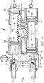
- Figure 4 is a longitudinal cross-sectional view along the line 4-4 of Figure 2 of the tandem cylinders illustrating the interconnection between the reservoir and the cylinders and showing the hydraulic oil passageways;
- Figure 5 is a longitudinal cross-sectional view along the line 4-4 and 5-5 of Figure 2 of the tandem cylinders illustrating the reservoir chamber and the fluid level indicator;
- Figure 6 is a cross-sectional view along the line 5-5 of Figure 2 of the reservoir chamber in the signal position;
- Figure 7 is a longitudinal section illustrating the power cylinder extending laterally relative to the length of the rotary actuator assembly and at a
position 90° from the position of Figure 2; - Figure 8 is a perspective view of another embodiment of the present invention in which the rotary actuator assembly includes a single cylinder; and
- Figure 9 is a longitudinal cross-sectional view of the rotary actuator assembly of Figure 8 having the single cylinder.
- In accordance with the present invention, a modular apparatus generally identified by the
reference numeral 10 is provided in which a power cylinder or like device is able to output, simultaneously or separately, linear motion and rotary motion. With reference first to Figure 1, theapparatus 10 includes arotary actuator assembly 12 that is air driven to convert linear motion to rotary motion. Therotary actuator assembly 12 is operably connected to arotary table assembly 14 that includes arotatable hub 16. The rotary motion, as indicated by a double headedarrow 17, of therotary actuator assembly 12 is coupled to thehub 16. Theapparatus 10 also includes apower cylinder 18 or like device that receives the outputtedrotary motion 17. - In the illustrated embodiment, the
power cylinder 18 includes aplate 20 that connects thepower cylinder 18 to thehub 16 of therotary table assembly 14. Although not shown, it is to be understood that thepower cylinder 18 may be directly connected to thehub 16 by an end portion thereof. In one embodiment, thepower cylinder 18 is, by itself, a non-rotating unit that is caused to rotate by the motion coupled to it through thehub 16. Thepower cylinder 18 is a conventional and well-known unit and includes a movable piston assembly having two piston rods and a piston. The piston assembly is adapted to move atooling plate 24 linearly and, with respect to Figure 1, is able to move vertically up-and-down as indicated by a double headedarrow 26. Suchvertical movement 26 is controlled using pressurized air (from a compressor 28) that passes through thecylinder wall 22 of thepower cylinder 18 and creates a force on the piston therein for the desiredmovement 26 of thetooling plate 24 thereof. - With reference to Figures 2 and 3, the
rotary table assembly 14 is more fully described. Therotary table assembly 14 includes atrantorque coupler 30 which provides interconnection between therotary actuator assembly 12 and thehub 16. Arotary shaft 32 is connected at one end to therotary actuator assembly 12 for rotational movement, as will be subsequently described in greater detail, and at another end to thetrantoraue coupler 30. In the embodiment as shown in Figure 2,longitudinal axis 13 through thecylinder 18 is generally coaxial with alongitudinal axis 15 of therotary shaft 32. - The
trantorque coupler 30, as best seen in Figure 3, comprises a segmentedinner sleeve 34 and a segmentedouter sleeve 36. Theinner sleeve 34 has an inside diameter D slightly larger than the outside diameter d of therotary shaft 32 to allow repositioning thereof along the linear axis of theshaft 32. A plurality ofcutouts 38 and onecutout 40 are formed in the segmentedinner sleeve 34. Thecutouts inner sleeve 34 to contract when engaged by theouter sleeve 36 around therotary shaft 32. Thecutout 40 is the only cutout on theinner sleeve 34 which does not terminate along a line spaced inwardly from anend 42 of theinner sleeve 34. - The
outer sleeve 36 comprises a plurality ofsegments 44 each separated alonglines 46. Ahex nut 48 has an innercircumferential groove 50 for mating with an outercircumferential groove 52 andprotrusion 54 on each of thesegments 44. Thehex nut 48 hasinternal threads 56 for receivingexternal threads 58 on theinner sleeve 34. Thehex nut 48 has a width W which is slightly smaller than a diameter B of thehub 16. Theouter sleeve 36 has an outer diameter b which is also slightly smaller than the diameter B of thehub 16. Asplit retainer ring 37 fits over thesegments 44 of theouter sleeve 36 for contact with thebore 60 of thehub 16. Thehub 16 has an innercircumferential glove 55 for receiving an "O"-ring 57 therein. - In operation, the
retainer ring 37 is positioned over theouter sleeve 36. Theinner sleeve 34 is threaded slightly into thehex nut 48 which is already mated with theouter sleeve 36. The assembledcoupler 30 is then inserted into thebore 60 of thehub 16 which is retained therein by the "O"-ring 57 until the entirerotary table assembly 14 is ready for attachment to therotary shaft 32 of therotary actuator assembly 12. Upon attachment to theshaft 32, thehex nut 48 is then tightened onto theinner sleeve 34 causing theinner sleeve 34 to contract around and tightly hold therotary shaft 32 and causing theouter sleeve 36 to expand into thering 37 and tightly hold thehub 16. Therefore, any rotational movement of therotary shaft 32 will be transmitted to thehub 16 through theinner sleeve 34, theouter sleeve 36 and theretainer ring 37 of thetrantorque coupler 30. - The
rotary table assembly 14 is attached to therotary actuator assembly 12 byfasteners 62 such as, for example, bolts through ahousing 64. Alock nut 66 is held within thehousing 64 by acircumferential flange 68 which is a part of thehousing 64. Thehub 16 is threaded into thelock nut 66 until ashoulder 70 thereof contacts athrust washer 74 on theflange 68. Athrust bearing 72 is inserted between thethrust washer 74 and anotherthrust washer 75. Similarly, athrust bearing 76 is installed between thelock nut 66 and theflange 68 with athrust washer bearings washers rotary table assembly 14. Awear band 80 is installed between thehub 16 and thehousing 64. Although not shown, it is to be understood that a grease fitting may be provided through thehousing 64 to allow the application of a lubricant therein if necessary. - Referring to Figures 4, 5 and 6, the
rotary actuator assembly 12 is shown in more detail. Referring first to Figure 4, therotary actuator assembly 12 comprises afirst cylinder 82 and asecond cylinder 84. Thecylinders rotary gear 90. Therotary shaft 32 is fit to therotary gear 90 by any appropriate method such as a key 92. Thecylinders outlet ports - The
first cylinder 82 hasfirst piston 98 abutting and asecond piston 100 affixed at opposite ends of therack gear 86. Thesecond cylinder 84 hasfirst piston 102 abutting and asecond piston 104 affixed at opposite ends of therack gear 88. Thepistons 98 through 104 are provided with appropriate seal rings 106 to form fluidtight chambers - Affixed to the first and
second cylinders ports oil reservoir assembly 116. Theassembly 116 comprises areservoir body 118 and first and secondflow control cartridges reservoir body 118, there are first andsecond cylinder passageways second cylinder passageways first end chambers passageways flow control cartridges second flow cartridges second cylinder passageways common passageway 132. - The control cartridges 120-122 are threaded into the
reservoir body 118 in order to provide control of the hydraulic oil therein. The cartridges 120-122 contain aball 134 andspring 136 for flow control, as is well known in the art. For example, in theflow control cartridge 120, thespring 136 holds theball 134 against ashoulder 138 to substantially prevent the flow of oil between thecommon passageway 132 and thefirst cylinder passageway 124. However, upon application of enough pressure to the hydraulic oil, theball 134 will press thespring 136 to allow oil to flow from thefirst cylinder passageway 124 into thecommon passageway 132. Additionally, thecartridges reservoir body 118 to provide passageways therearound. For example, thecartridge 120 is inserted to provide a gap between a leadingportion 138 thereof and ashoulder 140 of thefirst cylinder passageway 124. Thus, oil may flow between theleading edge 138 and theshoulder 140 in either direction. Therefore, it is possible to adjust rotational speed of therotary gear 82 and thus therotary shaft 32 by positioning thecartridges - In operation, compressed air is forced through the inlet/
outlet port 94 into thechamber 108. As the air enters thechamber 108, thepiston 98 is forced in a direction indicated by anarrow 142. As thepiston 98 moves in thedirection 142, therack gear 86 moves in thedirection 142 and forces thepiston 100 into thechamber 110. As thepiston 100 moves into thechamber 110, hydraulic oil therein is forced into thefirst cylinder passageway 124 past thecartridge 120 and into thecommon passageway 132. From thecommon passageway 132, the hydraulic oil bypasses the car-tridge 122 and enters thesecond cylinder passageway 126 and therefrom into thechamber 114. As the hydraulic oil is forced into thechamber 114, thepiston 104 is forced in a direction indicated by anarrow 144. The movement of thepiston 104 in thedirection 144 causes therack gear 88 to move in thedirection 144 and thus thepiston 102 moves in thedirection 144. Thus, air is forced from thechamber 112 out the inlet/outlet port 96. The action just described results in a clockwise rotation as indicated by anarrow 146 of therotary gear 90 and therotary shaft 32. As a result of the use of hydraulic oil and compressed air, the movement of therotary gear 90 is smooth and even. - Referring to Figure 5, a cross-sectional view of the rotary actuator assembly along the same line 4-4 as Figure 4 with a cross-sectional view of the
reservoir body 118 along the line 5-5 of Figure 2 is shown. In Figure 5, anoil indicator assembly 148 and areservoir chamber 150 are shown within thereservoir body 118. Thereservoir chamber 150 further includes areservoir port 152 for interconnection to the common passageway 132 (see Figure 4). Thereservoir port 152 is controlled by aball valve 154 which allows controlled flow from thechamber 150 to thecommon passageway 132 via a reservoir passageway 156 (see Figure 4). Although not shown, it is to be understood that theport 152 is further provided with a bleed capability to allow hydraulic oil to pass from thecommon passageway 132 back into thechamber 150. - The
oil indicator assembly 148 comprises aplunger 158, aspring 160 and apull ring 162. Thepull ring 162 is pivotally attached to theplunger 158 to provide a signal that hydraulic oil in thechamber 150 is low, as will be subsequently described in greater detail. Theplunger 158 is attached at an end opposite thering 162 to apiston 164 having apiston ring 166 thereon. Theplunger 158 passes through aplate 168 which is securely fastened to thereservoir body 118 by any appropriate method. Therefore, thespring 160 provides sufficient pressure against thepiston 164 to appropriately pressurize thechamber 150 for passage of hydraulic oil therefrom. - Referring to Figure 6, the
reservoir chamber 150 is shown with thepull ring 162 in the low oil indicating condition. Theplunger 158 is provided with a length appropriate to allow thepiston 164 to reach a point slightly above theport 152. At this point, thepull ring 162 which was gradually pivoted from the vertical condition as shown in Figure 5 to a vertical position 180° therefrom in Figure 6. Thus, an operator knows that thechamber 150 needs to be refilled with hydraulic oil. Since thechamber 150 is entirely within thereservoir body 118 and no air is within thechamber 150 for pressure purposes, therotary actuator assembly 12 may be oriented in any position without fear of hydraulic oil entering an air line as in the prior art. - Referring again to Figure 5, operation of the
rotary actuator assembly 12 in a direction opposite that of Figure 4 is illustrated. As compressed air enters thechamber 112 through theport 96, thepiston 102 is forced in thedirection 142. As thepiston 102 moves in thedirection 142, therack gear 88 and thepiston 104 also move in thedirection 142. Thus, the hydraulic oil in thechamber 114 is forced into thepassageway 126 and through and around thecartridge 122 into the common passageway 132 (see Figure 4). From thecommon passageway 132, the oil passes around thecartridge 120 into thepassageway 132 and thus into thechamber 110. The oil entering thechamber 110 forces thepiston 100, therack gear 86 and thepiston 98 in thedirection 144. Air within thechamber 108 is then forced out of theport 94. Therefore, therotary gear 90 is rotated in a counterclockwise direction as indicated by anarrow 170. - As previously described above with reference to Figure 4, the
flow control cartridges rotary gear 90. By opening or closing the gap between thecartridges respective passageways rotary gear 90 is rotated. Obviously, it is possible to have the gaps between thecartridges rotary actuator 12 provide a smooth rotation of therotary gear 90, but it also provides a fully controllable rotation speed as well as the ability to be positioned in any orientation. - Referring to Figure 7, an alternative arrangement utilizing the
rotary table assembly 14 of the present invention is illustrated. In the embodiment of Figure 7, apower cylinder 172 is positioned on therotatable hub 16 with itslongitudinal axis 174 being substantially perpendicular to thelongitudinal axis 15 of therotary shaft 32. Therefore, the orientation of thecylinder 172 is approximately 90° from the orientation of thecylinder 18 as shown in Figure 1 and Figure 2. Aplate 178 is fixed to a side of thecylinder 172 and to thehub 16. Thus, rotation of therotary shaft 32 by therotary actuator assembly 12 causes rotation of thecylinder 172 in a horizontal plane containing theaxis 174 and being perpendicular to the plane of the paper of Figure 7. - Thus, due to the
rotary table assembly 14, the orientation of a power cylinder may be varied between at least two positions. The first position as shown in Figures 1 and 2 places thelongitudinal axis 13 of thepower cylinder 18 generally coaxial with thelongitudinal axis 15 of therotary shaft 32. The second position, approximately 90° from the first position, places thelongitudinal axis 174 of thecylinder 172 generally perpendicular to theaxis 15 of theshaft 32. Therefore, rotational movement may be imparted to a linear movement device in various configurations for more flexibility than in the prior art devices. - Referring to Figure 8, an alternative embodiment of the
modular apparatus 10 is generally identified by thereference numeral 200. In the embodiment of Figure 8, arotary actuator assembly 202 comprises a singlepneumatic cylinder 204 as is known in the art. Air is provided to opposite ends of thecylinder 204 from acompressor 206 through inlet/outlet ports cylinder 204 provides rotary motion as indicated by double headedarrow 212 to therotary table assembly 14, thepower cylinder 18 is similarly rotated. Theapparatus 200 provides up-and-down motion in adirection 26 through action of thepower cylinder 18 as previously described above. Although not shown, it is to be understood that thepower cylinder 18 may be oriented 90° to the position shown in Figure 8 similarly to thecylinder 172 as described above with reference to Figure 7. - Referring to Figure 9, a cross-sectional view of the
rotary actuator assembly 202 is shown. As air is forced into afirst chamber 214 through theport 208, apiston 216 is forced in a direction indicated by anarrow 218. Arack gear 220 attached at one end to thepiston 216 and at another end to apiston 222 is thus forced in thedirection 218 pushing air from achamber 224 out theport 210. The movement of therack gear 220 in adirection 218 thus causes a rotational movement of arotary gear 226 in a clockwise direction as indicated by anarrow 228 due to the meshing therebetween. By forcing air into thechamber 224 through theport 210 and allowing air to escape from thechamber 214 through theport 208, an opposite rotation from thedirection 228 of therotary gear 226 is possible. Thus, theassembly 202 provides rotary motion in two directions to therotary table assembly 14. - The foregoing discussion of the invention has been presented for purposes of illustration and description. Further, the description is not intended to limit the invention to the form disclosed herein. Consequently, variations and modifications commensurate with the above teachings, within the skill and knowledge of the relevant art, are within the scope of the present invention. The embodiments described hereinabove are further intended to explain the best modes presently known of practicing the invention and to enable others skilled in the art to utilize the invention in such, or other embodiments, and with various modifications required by their particular applications or uses of the invention. It is intended that the appended claims be construed to include alternative embodiments to the extent permitted by the prior art.
Claims (19)
- A multi-axis apparatus, comprising:
rotary actuator means for providing rotary motion, said actuator means comprising a rotary gear and a rotary shaft attached thereto;
cylinder means for providing a linear motion, including a linearly movable piston in a cylinder body, wherein said cylinder means by itself is not able to rotate; and
rotary table means for connecting said rotary actuator means and said cylinder means, said rotary table means comprising a rotatable hub having a central bore therethrough and means for coupling which is attachable externally to said rotary shaft and internally to said central bore of said rotatable hub, said means for coupling transferring said rotary motion to said hub from said rotary actuator means, wherein substantially all of said cylinder means, including said piston and said cylinder body rotate and in which said rotary table means interconnects said cylinder means to said rotary actuator means in a selected one of two positions wherein, in a second position, a longitudinal axis of said cylinder means is substantially 90° different from said axis of said cylinder means in a first position. - An apparatus, as claimed in Claim 1, wherein: said rotary table means includes a housing connected to said rotary actuator means, said housing being non-rotatable.
- An apparatus, as claimed in Claim 1 or Claim 2, wherein:
said rotary table means includes fastener means for connecting said housing to said rotary actuator means. - An apparatus, as claimed in any one of Claims 1 to 3, wherein:
said rotary table means includes thrust bearing means for accepting axial and radial loads that are applied to said rotary table means. - An apparatus, as claimed in any one of Claims 1 to 4, wherein:
said rotary shaft of said rotary actuator means and said piston of said cylinder means are spaced from each other and are separate wherein there is no direct engagement between said shaft and said piston. - An apparatus, as claimed in any one of Claims 1 to 5, wherein:
said cylinder means includes plate means for connecting said rotary table means to said cylinder means in said selected one of said two positions. - An apparatus, as claimed in any one of Claims 1 to 6 wherein:
said rotary actuator means has one cylinder having a cylindrical casing with a rack and piston being movable relative to said casing and said rack and piston adapted to move using pressurized air in a selected one of two opposite directions. - An apparatus, as claimed in any one of Claims 1 to 7, wherein:
said rotary actuator includes two cylinders, each of said two cylinders including a cylindrical casing and having a rack and piston and hydraulic oil being disposed in at least one of the two cylindrical casings during operation of the apparatus. - A multi-axis apparatus, comprising:
rotary actuator means for providing rotary motion, said actuator means comprising:
two cylinders, each of said cylinders including a cylindrical casing and having a rack and piston with fluid being disposed in at least one of the two cylindrical casings during operation of the apparatus; and
reservoir means for containing said fluid, said reservoir means joined to end portions of said two cylinders;
cylinder means for linear motion including a linearly movable piston and a cylinder body, wherein said cylinder means by itself is not able to rotate; and
rotary table means connecting said rotary actuator means and said cylinder means for coupling said rotary motion of said rotary actuator means to said cylinder means, wherein substantially all of said cylinder means including said piston and said cylinder body rotate. - An apparatus, as claimed in Claim 9, wherein:
said reservoir means is a substantially completely enclosed unit and includes fluid level detecting means for providing an indication as to the amount of fluid in said reservoir means. - An apparatus, as claimed in Claim 10, wherein:
said fluid detecting means includes spring means for biasing said detecting means in a preselected direction, said spring means having portions contained within said reservoir means and indicator means operably connected to said spring means for providing an indication as to the level of fluid. - An apparatus, as claimed in Claim 11, wherein:
said spring means includes a plunger with an attached piston and a coiled spring surrounding said plunger with said plunger being movable relative to said reservoir means as said fluid level decreases. - An apparatus, as claimed in Claim 12, wherein:
said indicating means includes a pull ring connected to said plunger. - An apparatus, as claimed in any one of Claims 9 to 13, wherein:
said reservoir means includes a reservoir body having a first cylinder passageway and a second cylinder passageway, wherein each of said first and second cylinder passageways has an outlet end that is contiguously adjacent to one of said cylindrical casings. - An apparatus, as claimed in Claim 14, wherein:
said reservoir means includes a common passageway for interconnecting said first and second cylinder passageways to provide a fluid path between said first and second cylinder passageways. - An apparatus, as claimed in Claim 15, wherein:
said reservoir means includes first and second cartridge means for flow control, said first cartridge means being operatively associated with said first cylinder passageway for controlling fluid movement in said first cylinder passageway and said second cartridge means operatively associated with said second cylinder passageway for controlling fluid movement in said second cylinder passageway. - An apparatus, as claimed in any one of Claims 9 to 16, wherein:
said reservoir means includes a reservoir body having a reservoir chamber formed therein for housing fluid, said reservoir means also including a reservoir port for providing fluid from said reservoir chamber. - An apparatus, as claimed in any one of Claims 9 to 17, wherein:
said rotary actuator means includes a reservoir body for containing fluid that is a separate unit but connectable to end portions of said two cylinders. - A modular multi-axis apparatus, comprising:
rotary actuator means for providing rotary motion;
cylinder means for providing linear motion, including a linearly movable piston wherein said cylinder means by itself is not capable of rotation; and
rotary table means for interconnecting said rotary actuator means and said cylinder means, said cylinder means being connectable to said rotary table means in a selected one of at least two positions, wherein a longitudinal axis of said cylinder means is substantially 90° different in said two positions while said rotary actuator means remains in a same orientation for each of said two positions of said cylinder means.
Applications Claiming Priority (2)
| Application Number | Priority Date | Filing Date | Title |
|---|---|---|---|
| US07/598,387 US5117739A (en) | 1990-10-15 | 1990-10-15 | Fluid driven multi-axis apparatus |
| US598387 | 1990-10-15 |
Publications (2)
| Publication Number | Publication Date |
|---|---|
| EP0481692A2 true EP0481692A2 (en) | 1992-04-22 |
| EP0481692A3 EP0481692A3 (en) | 1992-08-12 |
Family
ID=24395355
Family Applications (1)
| Application Number | Title | Priority Date | Filing Date |
|---|---|---|---|
| EP19910309375 Withdrawn EP0481692A3 (en) | 1990-10-15 | 1991-10-11 | Multi-axis apparatus |
Country Status (2)
| Country | Link |
|---|---|
| US (1) | US5117739A (en) |
| EP (1) | EP0481692A3 (en) |
Cited By (3)
| Publication number | Priority date | Publication date | Assignee | Title |
|---|---|---|---|---|
| EP0564950A1 (en) * | 1992-04-10 | 1993-10-13 | UNIVER S.p.A. | Programmable rotary actuator |
| EP0669469A1 (en) * | 1994-02-26 | 1995-08-30 | Festo KG | Fluid driven rotary actuator |
| WO2004025127A1 (en) * | 2002-09-04 | 2004-03-25 | Luk Lamellen Und Kupplungsbau Beteiligungs Kg | Hydraulic device |
Families Citing this family (7)
| Publication number | Priority date | Publication date | Assignee | Title |
|---|---|---|---|---|
| DK171282B1 (en) * | 1993-04-07 | 1996-08-19 | Abb District Heating Managemen | Servo operated stop valve installation |
| US5900030A (en) * | 1996-10-15 | 1999-05-04 | Farmer Mold And Machine Works, Inc. | Apparatus for assembling a battery |
| US6397722B1 (en) | 1997-10-07 | 2002-06-04 | George D. Eddington | Variable torque accommodating, pressure fluid driven, transmissionless engine |
| US5950790A (en) | 1997-11-11 | 1999-09-14 | Barber; Steven C. | Linear stopping and positioning apparatus |
| US6312211B2 (en) | 1998-06-25 | 2001-11-06 | Protomark Corporation | Semi-automated load balancing mechanism |
| JP2003065302A (en) * | 2001-08-28 | 2003-03-05 | Smc Corp | Double rack pinion rotary actuator |
| US6988440B2 (en) * | 2002-07-18 | 2006-01-24 | Phd, Inc. | Rotary actuator assembly |
Citations (3)
| Publication number | Priority date | Publication date | Assignee | Title |
|---|---|---|---|---|
| FR1594419A (en) * | 1968-07-13 | 1970-06-01 | ||
| US3815479A (en) * | 1972-01-20 | 1974-06-11 | Phd Inc | Compound motion fluid actuator |
| FR2391383A1 (en) * | 1977-05-20 | 1978-12-15 | Huet Jean Pierre | JACK WITH TRANSLATION AND ROTATION MOVEMENTS |
Family Cites Families (12)
| Publication number | Priority date | Publication date | Assignee | Title |
|---|---|---|---|---|
| US477621A (en) * | 1892-06-21 | Half to frederick norris | ||
| US1689392A (en) * | 1923-07-21 | 1928-10-30 | Gardner Denver Co | Chuck-rotating mechanism |
| US3174406A (en) * | 1961-03-06 | 1965-03-23 | Moog Servocontrols Inc | Positioner |
| GB933424A (en) * | 1961-12-14 | 1963-08-08 | Mathews Engineering Company Lt | Improvements in or relating to rotary fluid pressure actuators |
| US4134306A (en) * | 1976-09-20 | 1979-01-16 | Phd, Inc. | Rotary actuator |
| US4111100A (en) * | 1977-03-07 | 1978-09-05 | Phd, Inc. | Non-rotatable fluid powered nozzle and valve combination |
| US4119017A (en) * | 1977-03-23 | 1978-10-10 | Phd, Inc. | Non-rotatable fluid power cylinder |
| US4202644A (en) * | 1978-07-10 | 1980-05-13 | Trantorque Corporation | Mounting device |
| SE425183B (en) * | 1978-12-18 | 1982-09-06 | Forenade Fabriksverken Ab | DOUBLE-OPEN CONNECTION |
| DE2905560C2 (en) * | 1979-02-14 | 1983-06-30 | Kocks Technik Gmbh & Co, 4010 Hilden | Clutch that can be engaged and disengaged |
| JPS57200707A (en) * | 1981-06-03 | 1982-12-09 | Torukaa:Kk | Swing/linear movement type actuator |
| US4665558A (en) * | 1984-12-28 | 1987-05-12 | Burke David W | Fluid-operated, linear-rotary, robot-like, actuator |
-
1990
- 1990-10-15 US US07/598,387 patent/US5117739A/en not_active Expired - Fee Related
-
1991
- 1991-10-11 EP EP19910309375 patent/EP0481692A3/en not_active Withdrawn
Patent Citations (3)
| Publication number | Priority date | Publication date | Assignee | Title |
|---|---|---|---|---|
| FR1594419A (en) * | 1968-07-13 | 1970-06-01 | ||
| US3815479A (en) * | 1972-01-20 | 1974-06-11 | Phd Inc | Compound motion fluid actuator |
| FR2391383A1 (en) * | 1977-05-20 | 1978-12-15 | Huet Jean Pierre | JACK WITH TRANSLATION AND ROTATION MOVEMENTS |
Cited By (3)
| Publication number | Priority date | Publication date | Assignee | Title |
|---|---|---|---|---|
| EP0564950A1 (en) * | 1992-04-10 | 1993-10-13 | UNIVER S.p.A. | Programmable rotary actuator |
| EP0669469A1 (en) * | 1994-02-26 | 1995-08-30 | Festo KG | Fluid driven rotary actuator |
| WO2004025127A1 (en) * | 2002-09-04 | 2004-03-25 | Luk Lamellen Und Kupplungsbau Beteiligungs Kg | Hydraulic device |
Also Published As
| Publication number | Publication date |
|---|---|
| EP0481692A3 (en) | 1992-08-12 |
| US5117739A (en) | 1992-06-02 |
Similar Documents
| Publication | Publication Date | Title |
|---|---|---|
| JP2986174B2 (en) | Tapping device for punch press | |
| US5117739A (en) | Fluid driven multi-axis apparatus | |
| US4830589A (en) | Variable stroke positive displacement pump | |
| EP0400846A2 (en) | Valves for fluids | |
| JPH04228964A (en) | Coupling mechanism of power extractor | |
| US3815479A (en) | Compound motion fluid actuator | |
| US4531897A (en) | Piston pump with a rotating piston | |
| US5485760A (en) | Ball nut and screw assemblies and methods of attaching extensions or housings to the ball nuts thereof | |
| US4811624A (en) | Hydraulically actuated stroke adjusting device | |
| CN108161982B (en) | Robot joint driver | |
| US5241895A (en) | Air-powered splined rotary actuator | |
| US5027667A (en) | Spring actuator with rollers | |
| DE69203278T2 (en) | Rotary valve for automatic transmission. | |
| US3967539A (en) | Variable stroke fluid cylinder | |
| US5083649A (en) | Clutch release mechanism | |
| US3899956A (en) | Linear electrohydraulic pulse drive actuator | |
| US5327793A (en) | Thrust bearings and bevel gears arrangement of marine propulsion unit | |
| US4041800A (en) | Stroke length adjusting devices | |
| US5657973A (en) | Device for gripping a workpiece | |
| CA2048901C (en) | Rotary servo actuator with internal valve | |
| EP0894982B1 (en) | Hydraulic servo device | |
| US4582183A (en) | Sliding displacement detecting apparatus | |
| US4753071A (en) | Self-powered rotating-cylinder type linear actuator utilizing rotation-generated centrifugal head for piston positioning | |
| US2813517A (en) | Hand-held hydraulic drill | |
| RU2155109C2 (en) | Controlled thrust mechanism of screw rolling mill |
Legal Events
| Date | Code | Title | Description |
|---|---|---|---|
| PUAI | Public reference made under article 153(3) epc to a published international application that has entered the european phase |
Free format text: ORIGINAL CODE: 0009012 |
|
| AK | Designated contracting states |
Kind code of ref document: A2 Designated state(s): CH DE DK GB LI SE |
|
| PUAL | Search report despatched |
Free format text: ORIGINAL CODE: 0009013 |
|
| AK | Designated contracting states |
Kind code of ref document: A3 Designated state(s): CH DE DK GB LI SE |
|
| STAA | Information on the status of an ep patent application or granted ep patent |
Free format text: STATUS: THE APPLICATION IS DEEMED TO BE WITHDRAWN |
|
| 18D | Application deemed to be withdrawn |
Effective date: 19930213 |