EP0481312A2 - Cutting device - Google Patents
Cutting device Download PDFInfo
- Publication number
- EP0481312A2 EP0481312A2 EP91117015A EP91117015A EP0481312A2 EP 0481312 A2 EP0481312 A2 EP 0481312A2 EP 91117015 A EP91117015 A EP 91117015A EP 91117015 A EP91117015 A EP 91117015A EP 0481312 A2 EP0481312 A2 EP 0481312A2
- Authority
- EP
- European Patent Office
- Prior art keywords
- blade
- cutting
- support members
- cutting device
- blades
- Prior art date
- Legal status (The legal status is an assumption and is not a legal conclusion. Google has not performed a legal analysis and makes no representation as to the accuracy of the status listed.)
- Granted
Links
Images
Classifications
-
- B—PERFORMING OPERATIONS; TRANSPORTING
- B26—HAND CUTTING TOOLS; CUTTING; SEVERING
- B26D—CUTTING; DETAILS COMMON TO MACHINES FOR PERFORATING, PUNCHING, CUTTING-OUT, STAMPING-OUT OR SEVERING
- B26D7/00—Details of apparatus for cutting, cutting-out, stamping-out, punching, perforating, or severing by means other than cutting
- B26D7/08—Means for treating work or cutting member to facilitate cutting
- B26D7/086—Means for treating work or cutting member to facilitate cutting by vibrating, e.g. ultrasonically
-
- Y—GENERAL TAGGING OF NEW TECHNOLOGICAL DEVELOPMENTS; GENERAL TAGGING OF CROSS-SECTIONAL TECHNOLOGIES SPANNING OVER SEVERAL SECTIONS OF THE IPC; TECHNICAL SUBJECTS COVERED BY FORMER USPC CROSS-REFERENCE ART COLLECTIONS [XRACs] AND DIGESTS
- Y10—TECHNICAL SUBJECTS COVERED BY FORMER USPC
- Y10S—TECHNICAL SUBJECTS COVERED BY FORMER USPC CROSS-REFERENCE ART COLLECTIONS [XRACs] AND DIGESTS
- Y10S83/00—Cutting
- Y10S83/929—Particular nature of work or product
- Y10S83/932—Edible
-
- Y—GENERAL TAGGING OF NEW TECHNOLOGICAL DEVELOPMENTS; GENERAL TAGGING OF CROSS-SECTIONAL TECHNOLOGIES SPANNING OVER SEVERAL SECTIONS OF THE IPC; TECHNICAL SUBJECTS COVERED BY FORMER USPC CROSS-REFERENCE ART COLLECTIONS [XRACs] AND DIGESTS
- Y10—TECHNICAL SUBJECTS COVERED BY FORMER USPC
- Y10T—TECHNICAL SUBJECTS COVERED BY FORMER US CLASSIFICATION
- Y10T83/00—Cutting
- Y10T83/04—Processes
-
- Y—GENERAL TAGGING OF NEW TECHNOLOGICAL DEVELOPMENTS; GENERAL TAGGING OF CROSS-SECTIONAL TECHNOLOGIES SPANNING OVER SEVERAL SECTIONS OF THE IPC; TECHNICAL SUBJECTS COVERED BY FORMER USPC CROSS-REFERENCE ART COLLECTIONS [XRACs] AND DIGESTS
- Y10—TECHNICAL SUBJECTS COVERED BY FORMER USPC
- Y10T—TECHNICAL SUBJECTS COVERED BY FORMER US CLASSIFICATION
- Y10T83/00—Cutting
- Y10T83/97—Miscellaneous
Definitions
- This invention is concerned with improvements relating to cutting, particularly by a method involving the use of high frequency (ultrasonic) vibration devices.
- the conventional method of ultrasonic cutting involves the use of a cutting blade which is mounted on an ultrasonic vibrating device with the blade lying in a plane containing the longitudinal axis of vibrations, and moving the blade through the article to be cut in said plane.
- Difficulty is also experienced in cutting materials which are brittle, e.g. honeycomb or crystalline materials.
- the vibrating device comprises one or more support members which are vibrated by the device, each support member supporting a plurality of blades.
- each blade is secured to a single support member at its centre.
- the present invention provides a cutting device comprising an ultrasonic vibrating device and a cutting blade mounted on the device so as to be vibrated thereby/therewith, the blade lying in a plane extending transversely to the longitudinal axis of vibration wherein the vibrating device comprises two or more support members, the cutting blade being supported by two adjacent support members.
- the blade is secured at its ends to the adjacent support members.
- the blade lies in a plane at right angles to the longitudinal axis of vibration.
- each support member is vibrated by the device, and each support member may comprise a plurality of blades, each lying in one of a plurality of parallel planes, desirably the blades being located at anti-nodes of the support member.
- the blades are conveniently made of steel e.g. graphite impregnated steel or tempered high tensile steel. They could be coated with chrome or polytetrafluoroethylene which may impart a non-stick surface.
- the cutting edge of the blade may be spark-eroded or otherwise cut to produce a hollow edge.
- the blades may be wide, narrow, thin or they may be wires. They may be round, triangular or roughly square in shape but preferably rectangular e.g. from 10 to 100 mm long and from 1 to 22 mm wide. When the blades are roughly square or rectangular in shape, they are advantageously profiled so that they are narrower along a portion of their lengths than at their ends. For example, from 40% to 90% and preferably from 50% to 70% of their length between the ends is narrower and the width may be up to 60% less than at the ends.
- the thickness of the blades may be from 0.25 to 1 mm and more usually from 0.3 to 0.6 mm, especially from 0.35 to 0.45 mm.
- Some at least of the support members may be secured to the vibrating device through the intermediary of node/anti-node displacement devices.
- the device comprises a vibrating mechanism to which the support member or support members are secured, the vibrating mechanism being in the form of a horn, preferably cylindrical or rectangular in shape, one surface of which is caused to vibrate at ultrasonic frequency.
- the number of support members is only limited by practical considerations and there may be, for instance, up to 20 support members
- the present invention also provides a method of cutting an article involving mounting a cutting blade on an ultrasonic vibrating device in a manner such that the blade lies in a plane extending transverse to the longitudinal axis of vibrations, and moving said blade in said plane through said article, wherein the vibrating device comprises two or more support members, the cutting blade being supported by two adjacent support members.
- the movement of the blade relating to the article to be cut may, if desired, be achieved by moving the article through the blade. However, it is also possible to move the blade through the article to be cut.
- a vibrating device 10 in the form of a cylindrical or rectangular shaped mother horn, the front face 11 of which is vibrated at ultrasonic frequency in the longitudinal direction E-F, the face 11 representing an anti-node of the device.
- Connected to the front face 11 are two or possibly several pairs of supporting devices 12 and 13 extending in the longitudinal direction E-F.
- blades 14, 15, 16 and 17 Mounted at spaced intervals between the supporting members 12 and 13 are blades 14, 15, 16 and 17. Each blade is connected at each end to the support member by an internal stud fastening 18 which passes through the apertures 19.
- the blades are 0.38 mm thick, 15 mm wide and 90 mm long.
- the cutting blades lie in a plane extending at right angles to the longitudinal axis of the support member, and are located on the support members at spaced anti-nodes. Thus in use, the blades will vibrate in a complicated mode, primarily in the direction E-F, and on passage through the article to be cut, will excavate a cut from the article, as the blade passes through the article.
- the device When the device is moved relative to the article to be cut, relative movement taking place in a direction at right angle to the longitudinal axis E-F, with the blades moving in the planes in which they lie, the article may be cut simultaneously by a plurality of cut lines.
Abstract
Description
- This invention is concerned with improvements relating to cutting, particularly by a method involving the use of high frequency (ultrasonic) vibration devices.
- The conventional method of ultrasonic cutting involves the use of a cutting blade which is mounted on an ultrasonic vibrating device with the blade lying in a plane containing the longitudinal axis of vibrations, and moving the blade through the article to be cut in said plane.
- Difficulty is experienced using conventional methods in that the depth of cut which is attainable is limited. For this reason ultrasonic cutting has in general been limited to thin articles, such as paper, cloth and thin plastic sheets. A significant problem exists in cutting blocks of substantial depth, and/or in providing a number of parallel cuts simultaneously.
- Difficulty is also experienced in cutting materials which are brittle, e.g. honeycomb or crystalline materials.
- In our co-pending EU-A-89109488.0 there is described and claimed a method and apparatus for cutting an article involving mounting a cutting blade on an ultrasonic vibrating device in a manner such that the blade lies in a plane extending transverse (preferably at right angles) to the longitudinal axis of vibrations, and moving said blade in said plane through said article.
- In this manner the blade moves back and forth transverse to the plane in which it moves through the article, effecting a removal of the material of the article along the line of cut. In one embodiment of the invention of EU-A-89109488.0, the vibrating device comprises one or more support members which are vibrated by the device, each support member supporting a plurality of blades.
- In the specific embodiments described in the detailed description as illustrated in the drawings of EU-A-89109488.0, each blade is secured to a single support member at its centre.
- We have now found that a cutting method and device falling within the claims of EU-A-89109488.0 where the blade is secured to adjacent support members, provides significantly more cutting power than where the blade is secured to a single support member.
- Accordingly the present invention provides a cutting device comprising an ultrasonic vibrating device and a cutting blade mounted on the device so as to be vibrated thereby/therewith, the blade lying in a plane extending transversely to the longitudinal axis of vibration wherein the vibrating device comprises two or more support members, the cutting blade being supported by two adjacent support members.
- Advantageously, the blade is secured at its ends to the adjacent support members. Preferably the blade lies in a plane at right angles to the longitudinal axis of vibration.
- The support members are vibrated by the device, and each support member may comprise a plurality of blades, each lying in one of a plurality of parallel planes, desirably the blades being located at anti-nodes of the support member.
- The blades are conveniently made of steel e.g. graphite impregnated steel or tempered high tensile steel. They could be coated with chrome or polytetrafluoroethylene which may impart a non-stick surface. The cutting edge of the blade may be spark-eroded or otherwise cut to produce a hollow edge.
- The blades may be wide, narrow, thin or they may be wires. They may be round, triangular or roughly square in shape but preferably rectangular e.g. from 10 to 100 mm long and from 1 to 22 mm wide. When the blades are roughly square or rectangular in shape, they are advantageously profiled so that they are narrower along a portion of their lengths than at their ends. For example, from 40% to 90% and preferably from 50% to 70% of their length between the ends is narrower and the width may be up to 60% less than at the ends. The thickness of the blades may be from 0.25 to 1 mm and more usually from 0.3 to 0.6 mm, especially from 0.35 to 0.45 mm.
- Some at least of the support members may be secured to the vibrating device through the intermediary of node/anti-node displacement devices.
- Preferably the device comprises a vibrating mechanism to which the support member or support members are secured, the vibrating mechanism being in the form of a horn, preferably cylindrical or rectangular in shape, one surface of which is caused to vibrate at ultrasonic frequency.
- The number of support members is only limited by practical considerations and there may be, for instance, up to 20 support members
The present invention also provides a method of cutting an article involving mounting a cutting blade on an ultrasonic vibrating device in a manner such that the blade lies in a plane extending transverse to the longitudinal axis of vibrations, and moving said blade in said plane through said article, wherein the vibrating device comprises two or more support members, the cutting blade being supported by two adjacent support members. - The movement of the blade relating to the article to be cut may, if desired, be achieved by moving the article through the blade. However, it is also possible to move the blade through the article to be cut.
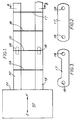
- The present invention will now be further illustrated by way of example only with reference to the accompanying drawings in which
- Figure 1
- represents a diagrammatic side sectional view of a cutting device according to the invention,
- Figure 2
- represents a view of a blade of Figure 1 looking in the direction of the arrows B-B, and
- Figure 3
- represents an alternative shape of the blade of Figure 2.
- The device which is the preferred embodiment of this invention comprises a
vibrating device 10 in the form of a cylindrical or rectangular shaped mother horn, thefront face 11 of which is vibrated at ultrasonic frequency in the longitudinal direction E-F, theface 11 representing an anti-node of the device. Connected to thefront face 11 are two or possibly several pairs of supportingdevices - Mounted at spaced intervals between the supporting
members blades internal stud fastening 18 which passes through theapertures 19. The blades are 0.38 mm thick, 15 mm wide and 90 mm long. - The cutting blades lie in a plane extending at right angles to the longitudinal axis of the support member, and are located on the support members at spaced anti-nodes. Thus in use, the blades will vibrate in a complicated mode, primarily in the direction E-F, and on passage through the article to be cut, will excavate a cut from the article, as the blade passes through the article.
- When the device is moved relative to the article to be cut, relative movement taking place in a direction at right angle to the longitudinal axis E-F, with the blades moving in the planes in which they lie, the article may be cut simultaneously by a plurality of cut lines.
Claims (11)
- A cutting device comprising an ultrasonic vibrating device and a cutting blade mounted on the device so as to be vibrated thereby/therewith, the blade lying in a plane extending transversely to the longitudinal axis of vibration wherein the vibrating device comprises two or more support members, the cutting blade being supported by two adjacent support members.
- A cutting device according to claim 1 wherein the blade is secured at its ends to the adjacent support members.
- A cutting device according to claim 1 in which the blade lies in a plane at right angles to the longitudinal axis of vibration.
- A cutting device according to claim 1 wherein the support members are vibrated by the device, and the support members comprise a plurality of blades, each lying in one of a plurality of parallel planes.
- A cutting device according to claim 1 wherein the blades are located at anti-nodes of the support members.
- A cutting device according to claim 1 wherein the blades are rectangular in shape having a length of from 10 to 100 mm and a width of from 1 to 22 mm.
- A cutting device according to claim 6 wherein the blades are narrower along a portion of their lengths then at their ends.
- A cutting device according to claim 1 wherein the thickness of the cutting blades is from 0.25 to 1 mm.
- A cutting device according to claim 1 wherein some at least of the support members are secured to the vibrating device through the intermediary of node/anti-node displacement devices.
- A cutting device according to claim 1 which comprises a vibrating mechanism to which the support members are secured, the vibrating mechanism being in the form of a horn, one surface of which is caused to vibrate at ultrasonic frequency.
- A method of cutting an article involving mounting a cutting blade on an ultrasonic vibrating device in a manner such that the blade lies in a plane extending transverse to the longitudinal axis of vibrations, and moving said blade in said plane through said article, wherein the vibrating device comprises two or more support members, the cutting blade being supported by two adjacent support members.
Applications Claiming Priority (2)
| Application Number | Priority Date | Filing Date | Title |
|---|---|---|---|
| GB9022844A GB2248795A (en) | 1990-10-19 | 1990-10-19 | Cutting device. |
| GB9022844 | 1990-10-19 |
Publications (3)
| Publication Number | Publication Date |
|---|---|
| EP0481312A2 true EP0481312A2 (en) | 1992-04-22 |
| EP0481312A3 EP0481312A3 (en) | 1992-07-08 |
| EP0481312B1 EP0481312B1 (en) | 1993-12-29 |
Family
ID=10684067
Family Applications (1)
| Application Number | Title | Priority Date | Filing Date |
|---|---|---|---|
| EP91117015A Expired - Lifetime EP0481312B1 (en) | 1990-10-19 | 1991-10-07 | Cutting device |
Country Status (11)
| Country | Link |
|---|---|
| US (1) | US5228372A (en) |
| EP (1) | EP0481312B1 (en) |
| JP (1) | JP2527862B2 (en) |
| AT (1) | ATE99214T1 (en) |
| CA (1) | CA2053722C (en) |
| DE (1) | DE69100892T2 (en) |
| DK (1) | DK0481312T3 (en) |
| ES (1) | ES2047975T3 (en) |
| GB (1) | GB2248795A (en) |
| PT (1) | PT99275B (en) |
| ZA (1) | ZA918141B (en) |
Cited By (3)
| Publication number | Priority date | Publication date | Assignee | Title |
|---|---|---|---|---|
| EP0584670A1 (en) * | 1992-08-28 | 1994-03-02 | Societe Des Produits Nestle S.A. | Ultrasonic cutting device |
| WO1994022645A1 (en) * | 1993-04-02 | 1994-10-13 | Rowenta-Werke Gmbh | Cutting device with piezoelectric oscillator |
| EP0768153A1 (en) * | 1995-10-11 | 1997-04-16 | Dr. Wolf und Partner Ingenieurbüro für Lebensmitteltechnik GmbH | Ultrasonically excited cutting system, in particular for cutting foodstuff |
Families Citing this family (23)
| Publication number | Priority date | Publication date | Assignee | Title |
|---|---|---|---|---|
| US5509256A (en) * | 1994-06-29 | 1996-04-23 | Groth; Ernest F. | Fibrous material packaging machine |
| US5914140A (en) * | 1994-10-25 | 1999-06-22 | General Mills, Inc. | Food products having acoustic bonds between food layers |
| GB2299046A (en) * | 1995-03-21 | 1996-09-25 | Nestle Sa | Ultrasonic cutting device |
| FR2735412B1 (en) * | 1995-06-19 | 1997-08-22 | Unir Ultra Propre Nutrition In | ULTRASONIC CUTTING DEVICE |
| US5785806A (en) * | 1996-07-22 | 1998-07-28 | Eastman Kodak Company | Ultrasonic cutting apparatus |
| US5861185A (en) * | 1996-08-22 | 1999-01-19 | Mars, Incorporated | Ultrasonic forming of confectionery products |
| US5871783A (en) | 1996-08-22 | 1999-02-16 | Mars, Incorporated | Apparatus for ultrasonically forming confectionery products |
| US5871793A (en) | 1996-11-27 | 1999-02-16 | Mars Incorporated | Puffed cereal cakes |
| US5846584A (en) | 1997-04-30 | 1998-12-08 | Mars, Incorporated | Apparatus and method for forming cereal food products |
| US6070509A (en) * | 1997-09-18 | 2000-06-06 | Colbourne Corporation | Method for ultrasonic cutting of food products |
| US6032561A (en) * | 1997-09-18 | 2000-03-07 | Colborne Corporation | Apparatus for ultrasonic cutting of food products |
| US20020127310A1 (en) * | 1998-12-07 | 2002-09-12 | Capodieci Roberto A. | Cereal food product and method |
| US6368647B1 (en) * | 1998-12-29 | 2002-04-09 | Mars, Incorporated | Ultrasonically activated continuous slitter apparatus and method |
| US6574944B2 (en) * | 2001-06-19 | 2003-06-10 | Mars Incorporated | Method and system for ultrasonic sealing of food product packaging |
| US6655948B2 (en) | 2001-08-31 | 2003-12-02 | Mars, Incorporated | System of ultrasonic processing of pre-baked food product |
| US6635292B2 (en) * | 2001-10-26 | 2003-10-21 | Mars, Incorporated | Ultrasonic rotary forming of food products |
| JP4692230B2 (en) * | 2005-11-01 | 2011-06-01 | 株式会社デンソー | Method for manufacturing ceramic honeycomb structure |
| US20070199423A1 (en) * | 2006-01-20 | 2007-08-30 | Roberto Capodieci | Apparatus and method for ultrasonic cutting |
| US20070196540A1 (en) * | 2006-01-31 | 2007-08-23 | Sweet Life, Inc. | Assembly line technique for food production and pull-apart food product and method |
| US20070178205A1 (en) * | 2006-01-31 | 2007-08-02 | Sweet Life, Inc. | Assembly line technique for pull-apart food production |
| US20090223152A1 (en) * | 2008-03-07 | 2009-09-10 | Cooper Technologies Company | Wire Tray Stock |
| DE102009036774A1 (en) * | 2009-08-08 | 2011-02-17 | Bizerba Gmbh & Co Kg | Cutting machine for food |
| WO2014157654A1 (en) * | 2013-03-29 | 2014-10-02 | 日本碍子株式会社 | Method for cutting honeycomb molding |
Citations (3)
| Publication number | Priority date | Publication date | Assignee | Title |
|---|---|---|---|---|
| FR656436A (en) * | 1928-06-25 | 1929-05-07 | Improvements made to devices for cutting materials into slices, in particular vegetables, sausages, etc. | |
| EP0353415A1 (en) * | 1988-06-03 | 1990-02-07 | Societe Des Produits Nestle S.A. | Cutting device |
| DE3838208A1 (en) * | 1988-11-11 | 1990-05-17 | Bondex S A | Apparatus for cutting foam |
Family Cites Families (4)
| Publication number | Priority date | Publication date | Assignee | Title |
|---|---|---|---|---|
| US2813377A (en) * | 1955-08-25 | 1957-11-19 | Raytheon Mfg Co | Multiple slicing tools |
| US3031804A (en) * | 1958-06-02 | 1962-05-01 | Charles J Thatcher | Ultrasonic slicing tool and method |
| US3471724A (en) * | 1965-04-08 | 1969-10-07 | Cavitron Corp | Magnetostrictive vibrator for high frequency machining of hard materials |
| US3416398A (en) * | 1966-07-05 | 1968-12-17 | Albert G. Bodine Jr. | Sonic cutting apparatus |
-
1990
- 1990-10-19 GB GB9022844A patent/GB2248795A/en not_active Withdrawn
-
1991
- 1991-10-07 DK DK91117015.7T patent/DK0481312T3/en active
- 1991-10-07 DE DE91117015T patent/DE69100892T2/en not_active Expired - Fee Related
- 1991-10-07 ES ES91117015T patent/ES2047975T3/en not_active Expired - Lifetime
- 1991-10-07 EP EP91117015A patent/EP0481312B1/en not_active Expired - Lifetime
- 1991-10-07 AT AT91117015T patent/ATE99214T1/en not_active IP Right Cessation
- 1991-10-11 ZA ZA918141A patent/ZA918141B/en unknown
- 1991-10-18 CA CA 2053722 patent/CA2053722C/en not_active Expired - Fee Related
- 1991-10-18 US US07/778,672 patent/US5228372A/en not_active Expired - Lifetime
- 1991-10-18 PT PT99275A patent/PT99275B/en not_active IP Right Cessation
- 1991-10-18 JP JP3271287A patent/JP2527862B2/en not_active Expired - Fee Related
Patent Citations (3)
| Publication number | Priority date | Publication date | Assignee | Title |
|---|---|---|---|---|
| FR656436A (en) * | 1928-06-25 | 1929-05-07 | Improvements made to devices for cutting materials into slices, in particular vegetables, sausages, etc. | |
| EP0353415A1 (en) * | 1988-06-03 | 1990-02-07 | Societe Des Produits Nestle S.A. | Cutting device |
| DE3838208A1 (en) * | 1988-11-11 | 1990-05-17 | Bondex S A | Apparatus for cutting foam |
Cited By (3)
| Publication number | Priority date | Publication date | Assignee | Title |
|---|---|---|---|---|
| EP0584670A1 (en) * | 1992-08-28 | 1994-03-02 | Societe Des Produits Nestle S.A. | Ultrasonic cutting device |
| WO1994022645A1 (en) * | 1993-04-02 | 1994-10-13 | Rowenta-Werke Gmbh | Cutting device with piezoelectric oscillator |
| EP0768153A1 (en) * | 1995-10-11 | 1997-04-16 | Dr. Wolf und Partner Ingenieurbüro für Lebensmitteltechnik GmbH | Ultrasonically excited cutting system, in particular for cutting foodstuff |
Also Published As
| Publication number | Publication date |
|---|---|
| DE69100892T2 (en) | 1994-05-11 |
| GB2248795A (en) | 1992-04-22 |
| JPH04275899A (en) | 1992-10-01 |
| DK0481312T3 (en) | 1994-04-25 |
| ZA918141B (en) | 1993-03-31 |
| US5228372A (en) | 1993-07-20 |
| PT99275B (en) | 1999-02-26 |
| PT99275A (en) | 1993-12-31 |
| ES2047975T3 (en) | 1994-03-01 |
| DE69100892D1 (en) | 1994-02-10 |
| EP0481312B1 (en) | 1993-12-29 |
| ATE99214T1 (en) | 1994-01-15 |
| EP0481312A3 (en) | 1992-07-08 |
| JP2527862B2 (en) | 1996-08-28 |
| CA2053722A1 (en) | 1992-04-20 |
| GB9022844D0 (en) | 1990-12-05 |
| CA2053722C (en) | 2000-05-23 |
Similar Documents
| Publication | Publication Date | Title |
|---|---|---|
| EP0481312B1 (en) | Cutting device | |
| EP0584670B1 (en) | Ultrasonic cutting device | |
| EP0353415B1 (en) | Cutting device | |
| US5226343A (en) | Ultrasonic cutting apparatus | |
| US5819615A (en) | Cutting process | |
| DE102007057468B4 (en) | Vibratory cutting device and method for vibration cutting | |
| EP0800900B1 (en) | Ultrasonic vibration cutter | |
| EP0733409A2 (en) | Cutting mechanism | |
| JP2001191299A (en) | Ultrasonic cutting system | |
| JPH04336996A (en) | Ultrasonic cutting device | |
| JP5486240B2 (en) | Ultrasonic cutting horn | |
| Tsujino et al. | Transmission conditions of vibration stresses to welding specimens of ultrasonic plastic welding using various two-vibration-system equipments | |
| GB2325192A (en) | Ultrasonic cutting device | |
| JPH0212719B2 (en) | ||
| JP2623632B2 (en) | Ultrasonic multi-blade wire cutter | |
| JPS62136398A (en) | Ultrasonic cutter | |
| SU1584774A1 (en) | Soil-tilling implement | |
| JPS61146496A (en) | Cutter | |
| JPH06270097A (en) | Roll paper cutter | |
| JPH06246677A (en) | Roll paper cutting device | |
| JPS59174317A (en) | Tool horn for ultrasonic welder | |
| JPH0350677B2 (en) |
Legal Events
| Date | Code | Title | Description |
|---|---|---|---|
| PUAI | Public reference made under article 153(3) epc to a published international application that has entered the european phase |
Free format text: ORIGINAL CODE: 0009012 |
|
| 17P | Request for examination filed |
Effective date: 19911007 |
|
| AK | Designated contracting states |
Kind code of ref document: A2 Designated state(s): AT BE CH DE DK ES FR GB GR IT LI LU NL SE |
|
| PUAL | Search report despatched |
Free format text: ORIGINAL CODE: 0009013 |
|
| AK | Designated contracting states |
Kind code of ref document: A3 Designated state(s): AT BE CH DE DK ES FR GB GR IT LI LU NL SE |
|
| 17Q | First examination report despatched |
Effective date: 19930607 |
|
| GRAA | (expected) grant |
Free format text: ORIGINAL CODE: 0009210 |
|
| AK | Designated contracting states |
Kind code of ref document: B1 Designated state(s): AT BE CH DE DK ES FR GB GR IT LI LU NL SE |
|
| REF | Corresponds to: |
Ref document number: 99214 Country of ref document: AT Date of ref document: 19940115 Kind code of ref document: T |
|
| REF | Corresponds to: |
Ref document number: 69100892 Country of ref document: DE Date of ref document: 19940210 |
|
| REG | Reference to a national code |
Ref country code: ES Ref legal event code: FG2A Ref document number: 2047975 Country of ref document: ES Kind code of ref document: T3 |
|
| ET | Fr: translation filed | ||
| ITF | It: translation for a ep patent filed |
Owner name: SOCIETA' ITALIANA BREVETTI S.P.A. |
|
| REG | Reference to a national code |
Ref country code: DK Ref legal event code: T3 |
|
| REG | Reference to a national code |
Ref country code: GR Ref legal event code: FG4A Free format text: 3011004 |
|
| ITTA | It: last paid annual fee | ||
| PLBE | No opposition filed within time limit |
Free format text: ORIGINAL CODE: 0009261 |
|
| STAA | Information on the status of an ep patent application or granted ep patent |
Free format text: STATUS: NO OPPOSITION FILED WITHIN TIME LIMIT |
|
| 26N | No opposition filed | ||
| EAL | Se: european patent in force in sweden |
Ref document number: 91117015.7 |
|
| REG | Reference to a national code |
Ref country code: GB Ref legal event code: IF02 |
|
| PGFP | Annual fee paid to national office [announced via postgrant information from national office to epo] |
Ref country code: GR Payment date: 20040924 Year of fee payment: 14 |
|
| PGFP | Annual fee paid to national office [announced via postgrant information from national office to epo] |
Ref country code: DE Payment date: 20040930 Year of fee payment: 14 |
|
| PGFP | Annual fee paid to national office [announced via postgrant information from national office to epo] |
Ref country code: NL Payment date: 20041003 Year of fee payment: 14 |
|
| PGFP | Annual fee paid to national office [announced via postgrant information from national office to epo] |
Ref country code: SE Payment date: 20041006 Year of fee payment: 14 |
|
| PGFP | Annual fee paid to national office [announced via postgrant information from national office to epo] |
Ref country code: FR Payment date: 20041008 Year of fee payment: 14 |
|
| PGFP | Annual fee paid to national office [announced via postgrant information from national office to epo] |
Ref country code: AT Payment date: 20041013 Year of fee payment: 14 Ref country code: LU Payment date: 20041013 Year of fee payment: 14 |
|
| PGFP | Annual fee paid to national office [announced via postgrant information from national office to epo] |
Ref country code: DK Payment date: 20041014 Year of fee payment: 14 |
|
| PGFP | Annual fee paid to national office [announced via postgrant information from national office to epo] |
Ref country code: CH Payment date: 20041015 Year of fee payment: 14 |
|
| PGFP | Annual fee paid to national office [announced via postgrant information from national office to epo] |
Ref country code: ES Payment date: 20041116 Year of fee payment: 14 |
|
| PGFP | Annual fee paid to national office [announced via postgrant information from national office to epo] |
Ref country code: BE Payment date: 20041215 Year of fee payment: 14 |
|
| PG25 | Lapsed in a contracting state [announced via postgrant information from national office to epo] |
Ref country code: IT Free format text: LAPSE BECAUSE OF NON-PAYMENT OF DUE FEES Effective date: 20051007 Ref country code: AT Free format text: LAPSE BECAUSE OF NON-PAYMENT OF DUE FEES Effective date: 20051007 |
|
| PG25 | Lapsed in a contracting state [announced via postgrant information from national office to epo] |
Ref country code: SE Free format text: LAPSE BECAUSE OF NON-PAYMENT OF DUE FEES Effective date: 20051008 Ref country code: ES Free format text: LAPSE BECAUSE OF NON-PAYMENT OF DUE FEES Effective date: 20051008 |
|
| PG25 | Lapsed in a contracting state [announced via postgrant information from national office to epo] |
Ref country code: BE Free format text: LAPSE BECAUSE OF NON-PAYMENT OF DUE FEES Effective date: 20051031 Ref country code: LU Free format text: LAPSE BECAUSE OF NON-PAYMENT OF DUE FEES Effective date: 20051031 Ref country code: DK Free format text: LAPSE BECAUSE OF NON-PAYMENT OF DUE FEES Effective date: 20051031 Ref country code: LI Free format text: LAPSE BECAUSE OF NON-PAYMENT OF DUE FEES Effective date: 20051031 Ref country code: CH Free format text: LAPSE BECAUSE OF NON-PAYMENT OF DUE FEES Effective date: 20051031 |
|
| PG25 | Lapsed in a contracting state [announced via postgrant information from national office to epo] |
Ref country code: NL Free format text: LAPSE BECAUSE OF NON-PAYMENT OF DUE FEES Effective date: 20060501 |
|
| PG25 | Lapsed in a contracting state [announced via postgrant information from national office to epo] |
Ref country code: DE Free format text: LAPSE BECAUSE OF NON-PAYMENT OF DUE FEES Effective date: 20060503 |
|
| REG | Reference to a national code |
Ref country code: DK Ref legal event code: EBP |
|
| REG | Reference to a national code |
Ref country code: CH Ref legal event code: PL |
|
| EUG | Se: european patent has lapsed | ||
| PG25 | Lapsed in a contracting state [announced via postgrant information from national office to epo] |
Ref country code: FR Free format text: LAPSE BECAUSE OF NON-PAYMENT OF DUE FEES Effective date: 20060630 |
|
| NLV4 | Nl: lapsed or anulled due to non-payment of the annual fee |
Effective date: 20060501 |
|
| REG | Reference to a national code |
Ref country code: FR Ref legal event code: ST Effective date: 20060630 |
|
| REG | Reference to a national code |
Ref country code: ES Ref legal event code: FD2A Effective date: 20051008 |
|
| REG | Reference to a national code |
Ref country code: GB Ref legal event code: 732E |
|
| BERE | Be: lapsed |
Owner name: SOC. DES PRODUITS *NESTLE S.A. Effective date: 20051031 |
|
| PG25 | Lapsed in a contracting state [announced via postgrant information from national office to epo] |
Ref country code: GR Free format text: LAPSE BECAUSE OF NON-PAYMENT OF DUE FEES Effective date: 19931229 |
|
| PGFP | Annual fee paid to national office [announced via postgrant information from national office to epo] |
Ref country code: GB Payment date: 20071017 Year of fee payment: 17 |
|
| GBPC | Gb: european patent ceased through non-payment of renewal fee |
Effective date: 20081007 |
|
| PG25 | Lapsed in a contracting state [announced via postgrant information from national office to epo] |
Ref country code: GB Free format text: LAPSE BECAUSE OF NON-PAYMENT OF DUE FEES Effective date: 20081007 |