EP0480904B1 - Incremental length measuring system - Google Patents
Incremental length measuring system Download PDFInfo
- Publication number
- EP0480904B1 EP0480904B1 EP91890210A EP91890210A EP0480904B1 EP 0480904 B1 EP0480904 B1 EP 0480904B1 EP 91890210 A EP91890210 A EP 91890210A EP 91890210 A EP91890210 A EP 91890210A EP 0480904 B1 EP0480904 B1 EP 0480904B1
- Authority
- EP
- European Patent Office
- Prior art keywords
- casing
- measuring system
- length
- scale
- reference mark
- Prior art date
- Legal status (The legal status is an assumption and is not a legal conclusion. Google has not performed a legal analysis and makes no representation as to the accuracy of the status listed.)
- Expired - Lifetime
Links
Images

Classifications
-
- G—PHYSICS
- G01—MEASURING; TESTING
- G01D—MEASURING NOT SPECIALLY ADAPTED FOR A SPECIFIC VARIABLE; ARRANGEMENTS FOR MEASURING TWO OR MORE VARIABLES NOT COVERED IN A SINGLE OTHER SUBCLASS; TARIFF METERING APPARATUS; MEASURING OR TESTING NOT OTHERWISE PROVIDED FOR
- G01D5/00—Mechanical means for transferring the output of a sensing member; Means for converting the output of a sensing member to another variable where the form or nature of the sensing member does not constrain the means for converting; Transducers not specially adapted for a specific variable
- G01D5/12—Mechanical means for transferring the output of a sensing member; Means for converting the output of a sensing member to another variable where the form or nature of the sensing member does not constrain the means for converting; Transducers not specially adapted for a specific variable using electric or magnetic means
- G01D5/244—Mechanical means for transferring the output of a sensing member; Means for converting the output of a sensing member to another variable where the form or nature of the sensing member does not constrain the means for converting; Transducers not specially adapted for a specific variable using electric or magnetic means influencing characteristics of pulses or pulse trains; generating pulses or pulse trains
- G01D5/245—Mechanical means for transferring the output of a sensing member; Means for converting the output of a sensing member to another variable where the form or nature of the sensing member does not constrain the means for converting; Transducers not specially adapted for a specific variable using electric or magnetic means influencing characteristics of pulses or pulse trains; generating pulses or pulse trains using a variable number of pulses in a train
- G01D5/2454—Encoders incorporating incremental and absolute signals
- G01D5/2455—Encoders incorporating incremental and absolute signals with incremental and absolute tracks on the same encoder
- G01D5/2457—Incremental encoders having reference marks
-
- H—ELECTRICITY
- H03—ELECTRONIC CIRCUITRY
- H03M—CODING; DECODING; CODE CONVERSION IN GENERAL
- H03M1/00—Analogue/digital conversion; Digital/analogue conversion
- H03M1/12—Analogue/digital converters
- H03M1/22—Analogue/digital converters pattern-reading type
- H03M1/24—Analogue/digital converters pattern-reading type using relatively movable reader and disc or strip
- H03M1/28—Analogue/digital converters pattern-reading type using relatively movable reader and disc or strip with non-weighted coding
- H03M1/30—Analogue/digital converters pattern-reading type using relatively movable reader and disc or strip with non-weighted coding incremental
- H03M1/308—Analogue/digital converters pattern-reading type using relatively movable reader and disc or strip with non-weighted coding incremental with additional pattern means for determining the absolute position, e.g. reference marks
Definitions
- the invention relates to an incremental length measuring system, with a scale having a measuring graduation, a scanning unit with scanning elements for generating measuring signals during the scanning of the measuring graduation and an evaluation unit for these measuring signals, wherein a reference track parallel to the measuring graduation with several reference marks each corresponding to a reference point, assigned scanning elements Provided in the scanning unit and a selection switch that can be actuated by an assignment to a reference mark in a protective housing for the scale and the scanning unit and that can be adjusted with the scanning unit and that generates or emits a reference pulse only at at least one reference mark selected via the permanent magnet allows.
- a selection option for reference marks is provided in order to simplify the manufacture of the measuring systems and, as far as possible, without any external intervention in the encapsulation of the measuring system, the selection of a specific, e.g. B. to enable the machine zero point of a machine tool corresponding reference point and thus to be able to relate the measurements to the machine zero point.
- a selection of reference marks also makes sense in other cases if measurements related to them are to be carried out. From DE-A 18 14 785 mechanical on-off switches are known which are actuated by stops during the adjustment of the scanning unit and which activate the evaluation circuit only at preselected reference marks.
- the main object of the invention is to create a length measuring system of the type mentioned, in which a selection of any reference marks is made possible with simple means and without intervention in the interior of the protective housing and the selection made can be changed if necessary.
- a partial object of the invention is to create a length measuring system in which longitudinal displacements of the scale body in the area of the selected reference mark are prevented even if the selected reference mark is not exactly in the center of the scale.
- a permanent magnet is permanently assigned to each selectable reference mark in the protective housing and can be adjusted via actuators from an inactive position with respect to the selection switch to an active position.
- Simple devices can be used for the adjustment of the permanent magnets from the active to the inactive and vice versa. Since a permanent magnet is assigned to each selectable reference mark anyway, no modifications or longer installation work on the length measuring system are required.
- each permanent magnet is adjustably attached with a support which can be rotated or pivoted in the housing from a position which rejects the movement path of the selection switch into a position which activates the switch when it is moved past.
- the selection switch is mounted in an outer driver for the scanning unit and the permanent magnets are mounted with their carriers in a receiving bore or groove provided in the longitudinal direction alongside this driver in the protective housing and are adjustable from the outside of the housing.
- This version has the advantage that the scanning unit and scale for length measuring systems can be constructed in the same way without selecting a reference point, and if the protective housing contains corresponding receiving devices for the permanent magnets and the driver receiving devices for the switch, it is also possible to retrofit the measuring system with selection devices.
- the permanent magnets are accommodated in the protective housing on supports which can be adjusted via external actuators.
- These permanent magnets can be seated on flaps with foot parts in longitudinal grooves of the housing, which is usually formed from an extruded aluminum profile, can be pivoted through closable housing openings and can be locked in the pivoting end positions.
- One embodiment variant which enables simple construction and easy assembly of the permanent magnets, is characterized in that as a carrier for the permanent magnets, at least over the length of the attachment area of the selectable reference marks on the scale, but preferably over the entire scale length, is made of elastic, in particular rubber-elastic, profile tape Deformable material is provided, which engages with a foot part at an edge in the clamp seat in a holding groove inside the tubular protective housing and carries the permanent magnets associated with the individual reference marks at a distance from the foot part outside the activation area for the switch, with a closable housing opening in the area of each reference mark is provided, via which the band can be bent in this area around the foot part by inserted screws or press-in bodies, so that the associated permanent magnet is adjusted in the activation area for the switch.
- an elastically deformable band held on both edges in grooves in the protective housing which is concavely curved in relation to the interior of the housing in the inactive position and which, in the area of an activated magnet, assumes a concave curvature by being pushed in by means of the screw or the press-in body.
- the housing is additionally sealed against the housing openings for the screws or press-in bodies by a tape attached in this way.
- the actuators and / or carriers for the permanent magnets in their position holding the permanent magnet in the activation position at the same time the in the housing in a groove to compensate for different thermal expansions of the housing, scale or the object equipped with the length measuring system to the required extent, by means of flexible holders that are held longitudinally adjustable in the area of the selected reference mark, in particular clamp.
- the protective housing forming a carrier can preferably be fixed immovably in the longitudinal direction on the object with one or more holding elements in the area of the selected reference mark, so that the selected reference mark coincides with the fixed point of the protective housing and thus normally also with the machine zero point.
- the overall construction described can also be used if no permanent magnets are used to select a reference mark.
- these permanent magnets are replaced by the same actuators, with the help of which the scale can be clamped.
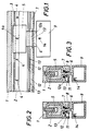
- a scanning unit 5 is adjustable, which has only been illustrated in its outlines and has known lighting and reception devices for optoelectronic scanning of the measuring graduation 3 and the reference marks 4, with the aid of which scanning signals converting the measuring graduation 3 into count signals and 4 reference pulses can be generated by scanning the reference marks.
- the scanning unit 5 sits on a sword-like support 6 and is guided with this between sealing lips 7 through a slot-shaped housing opening 8 to the outside, where it is coupled to a driver 9, from which a cable 10 also shown in FIG. 8 to an evaluation or Display unit for displaying the measurement result.
- the length measuring system is known in principle.
- each carrier 12 or 12a is equipped with a permanent magnet 13 which, only in its activation position, is capable of activating a relay or another switch 14 attached in the driver 9.
- Each carrier 12 is assigned to a reference mark 4, so that a reference pulse generated at the assigned reference mark 4a during scanning is used in the measuring system only when switch 14 is activated.
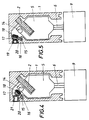
- each reference mark on the scale body 2 is associated with a flap-like carrier 17 which is held by a base part 15 in a molded-in housing groove 16 and carries a permanent magnet 18.
- each selectable reference mark and thus each flap 17 is assigned an opening which can be closed by a stopper 19.
- the flap 17 is adjusted with the aid of a suitable tool from the position shown in FIG. 5 to the position shown in FIG. 4, with the flap 17 being secured in the position shown in FIG 4 position shown can be made. Furthermore, the flap is secured by a larger plug 21.
- a permanent magnet 18 in the position according to FIG. 4 activates the switch 14 when the scanning unit 5 moves past in the sense of an evaluation of the reference pulse generated at the assigned reference mark.
- the scale body 2 is fixed with its longitudinal edge in a groove 22 of the protective housing 1 so that it can be moved longitudinally to a limited extent, for which purpose an elastically flexible holder 23 is provided which fills the groove 22 around the edge of the scale body 2.
- This bracket can be made of an elastomer, e.g. B. silicone rubber. But it is also possible to cross the longitudinal direction or use diagonally corrugated spring bodies.
- the scanning unit 5 is again provided with a selection switch 24.
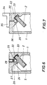
- Each selectable reference mark is assigned a carrier body 26 with a permanent magnet 27, which is chamfered on one side in its basic shape and is shown in FIG. 6 in its inactive position in a groove 25 that is open to the groove 22 and has a circular segment-shaped cross section that is open to the groove 22. Openings are provided in the ceiling of the housing by means of plugs 28, via which the body 26, like the body 12 according to FIGS. 2 and 3, can be rotated so that the permanent magnet 27 reaches an activation area for the switch 24.
- the body 26 originally aligned with its chamfer with the groove wall moves into the groove 22 from the side and thereby clamps the scale body 2 in the region of the selected reference mark on the housing 1 due to the narrowing of the groove 22 while compressing the element 23 firmly.
- the closable by the plug 28 openings can be formed as threaded openings, so that in the area of the selected reference mark, a holding element 29 for the scale housing 1 can be fastened by means of screws 31 penetrating through its foot part 30 and engaging in the openings released by the plugs 28. Through elongated holes 32 of the element 29, fastening screws for fixing the measuring system can be attached to a machine.
- a longitudinal slot 33 is connected to the openings forming thread openings in the central area against the scale ends.
- Holding elements 34 provided here for the housing 1 carry 35 lower parts 36 on their lower flange, the shape of which is adapted to the coherent cross-section of slot 33 and groove 25, so that they can be moved longitudinally and to the extent necessary a longitudinal adjustment of the housing relative to the fastening points of these fastening elements 34 on the object.
- the ends of the housing 1 can be closed by cover 37.
Description
Die Erfindung betrifft ein inkrementales Längenmeßsystem, mit einem eine Meßteilung aufweisenden Maßstab, einer Abtasteinheit mit Abtastelementen zur Erzeugung von Meßsignalen bei der Abtastung der Meßteilung und einer Auswertungseinheit für diese Meßsignale, wobei eine zur Meßteilung parallele Referenzspur mit mehreren je einem Bezugspunkt entsprechenden Referenzmarken, zugeordnete Abtastelemente in der Abtasteinheit und ein von einem in Zuordnung zu einer Referenzmarke in einem Schutzgehäuse für den Maßstab und die Abtasteinheit anbringbaren Dauermagneten betätigbarer, mit der Abtasteinheit verstellbarer Auswahlschalter vorgesehen sind, der eine Erzeugung bzw. Abgabe eines Referenzimpulses nur an wenigstens einer über den Dauermagneten ausgewählten Referenzmarke zuläßt.The invention relates to an incremental length measuring system, with a scale having a measuring graduation, a scanning unit with scanning elements for generating measuring signals during the scanning of the measuring graduation and an evaluation unit for these measuring signals, wherein a reference track parallel to the measuring graduation with several reference marks each corresponding to a reference point, assigned scanning elements Provided in the scanning unit and a selection switch that can be actuated by an assignment to a reference mark in a protective housing for the scale and the scanning unit and that can be adjusted with the scanning unit and that generates or emits a reference pulse only at at least one reference mark selected via the permanent magnet allows.
Bei derartigen Längenmeßsystemen wird eine Auswahlmöglichkeit für Referenzmarken vorgesehen, um die Herstellung der Meßsysteme zu vereinfachen und möglichst ohne äußeren Eingriff in die Kapselung des Meßsystemes die Auswahl eines bestimmten,z. B. dem Maschinen-Nullpunkt einer Werkzeugmaschine entsprechenden Referenzpunktes zu ermöglichen und die Messungen damit auf den Maschinen-Nullpunkt beziehen zu können. Eine Auswahl von Referenzmarken ist auch in anderen Fällen sinnvoll, wenn auf sie bezogene Messungen durchzuführen sind. Aus der DE-A 18 14 785 sind mechanische Ein- Ausschalter bekannt, die bei der Verstellung der Abtasteinheit über Anschläge betätigt werden und die Auswertungsschaltung nur an vorgewählten Referenzmarken aktivieren. Längenmeßsysteme der eingangs genannten Art, bei denen an vorwählbaren Maßstabstellen anbringbare Dauermagnete zur Betätigung von als in der Abtasteinheit integrierten Reed-Relais Verwendung finden, sind aus der DE-B2 25 40 412 bekannt. Die Anbringung solcher Dauermagnete am Maßstab erfordert bei gekapselten Längenmeßsystemen einen unerwünschten Eingriff ins Innere des Schutzgehäuses. Ferner besteht bei der meist üblichen Klemmbefestigung des Dauermagneten am Maßstabkörper die Gefahr, daß dieser Dauermagnet bei längerer Betriebszeit verrutscht oder abfällt. Es wurde deshalb schon vorgeschlagen, im Schutzgehäuse eine von dem Maßstab und Abtasteinheit aufnehmenden Innenraum getrennte Längsbohrung vorzusehen, in die der Dauermagnet vom Gehäuseende her eingeschoben wird, wobei dieser Dauermagnet durch die Bohrung bis zu beiden Enden ausfüllende Distanzstücke in seiner Lage gesichert wird. Hier ergibt sich eine aufwendige Montage und das Maßstabgehäuse muß an den Enden für das Einfädeln bzw. Herausziehen des Dauermagneten und der Distanzstücke zugänglich sein.In such length measuring systems, a selection option for reference marks is provided in order to simplify the manufacture of the measuring systems and, as far as possible, without any external intervention in the encapsulation of the measuring system, the selection of a specific, e.g. B. to enable the machine zero point of a machine tool corresponding reference point and thus to be able to relate the measurements to the machine zero point. A selection of reference marks also makes sense in other cases if measurements related to them are to be carried out. From DE-A 18 14 785 mechanical on-off switches are known which are actuated by stops during the adjustment of the scanning unit and which activate the evaluation circuit only at preselected reference marks. Length measuring systems The type mentioned at the beginning, in which permanent magnets which can be attached to preselectable scale positions for actuating reed relays integrated in the scanning unit, are known from DE-B2 25 40 412. The attachment of such permanent magnets to the scale requires an undesirable intervention in the interior of the protective housing in encapsulated length measuring systems. Furthermore, with the usually usual clamp fastening of the permanent magnet to the scale body, there is the danger that this permanent magnet will slip or fall off over a longer period of time. It has therefore already been proposed to provide in the protective housing a longitudinal bore separate from the scale and scanning unit, into which the permanent magnet is inserted from the end of the housing, this permanent magnet being secured in position by the bore filling fillers to both ends. This results in a complex assembly and the scale housing must be accessible at the ends for threading or pulling out the permanent magnet and the spacers.
Für genauere Messungen ist es erwünscht, daß bei unterschiedlichen Wärmedehnungen des Maßstabkörpers, des Schutzgehäuses und des Objektes, auf dem das Längenmeßsystem montiert ist, im Normalfall das Bett einer Werkzeugmaschine, keine merkbare Verstellung der ausgewählten Referenzmarke gegenüber dem Maschinen-Nullpunkt stattfindet. Es wurde versucht, den Maßstab nur im Bereich seiner Längsmitte unter Verwendung eines Klebers geringer Elastizität im Schutzgehäuse festzulegen, durch nachgiebige Befestigung der übrigen Maßstabteile aber eine Längsverstellung dieser Teile gegenüber dem Schutzgehäuse zuzulassen und auch das Schutzgehäuse durch eine Mittelbefestigung gegenüber dem Objekt festzulegen, wobei bisher für die Enden des Schutzgehäuses zwar starre Befestigungsstellen am Objekt, aber zwischen diesen Befestigungsblöcken und dem Ende des Schutzgehäuses linear verstellbare Elemente, z. b. besonders geformte Federn, Gelenkverbindungen mit einander kreuzenden Gelenkachsen u. dgl. vorgesehen werden. Diese Art der Montage ist aufwendig und erfüllt nur dann tatsächlich die gestellte Aufgabe, wenn die starre Befestigung des Maßstabgehäuses bzw. die Festlegung des Maßstabkörpers gegenüber dem Schutzgehäuse tatsächlich zufällig am Maschinen-Nullpunkt erfolgt.For more precise measurements, it is desirable that, in the case of different thermal expansions of the scale body, the protective housing and the object on which the length measuring system is mounted, the bed of a machine tool, no noticeable adjustment of the selected reference mark relative to the machine zero point takes place. An attempt was made to fix the scale only in the area of its longitudinal center using a low-elastic adhesive in the protective housing, but to allow longitudinal adjustment of these parts relative to the protective housing by resilient fastening of the other scale parts, and also to fix the protective housing by means of a central fastening relative to the object, so far for the ends of the protective housing rigid attachment points on the object, but between these mounting blocks and the end of the protective housing linearly adjustable elements, eg specially shaped springs, articulated connections with intersecting joint axes u. Like. Be provided. This type of assembly is complex and only really fulfills the task when the rigid attachment of the scale housing or the fixing of the scale body relative to the protective housing actually happens accidentally at the machine zero point.
Hauptaufgabe der Erfindung ist die Schaffung eines Längenmeßsystems der eingangs genannten Art, bei dem eine Auswahl beliebiger Referenzmarken mit einfachen Mitteln und ohne Eingriff in den Innenraum des Schutzgehäuses ermöglicht wird und die getroffene Auswahl im Bedarfsfall geändert werden kann. Eine Teilaufgabe der Erfindung besteht in der Schaffung eines Längenmeßsystems, bei dem Längsverschiebungen des Maßstabkörpers im Bereich der ausgewählten Referenzmarke auch dann verhindert werden, wenn die ausgewählte Referenzmarke sich nicht genau in der Maßstablängsmitte befindet.The main object of the invention is to create a length measuring system of the type mentioned, in which a selection of any reference marks is made possible with simple means and without intervention in the interior of the protective housing and the selection made can be changed if necessary. A partial object of the invention is to create a length measuring system in which longitudinal displacements of the scale body in the area of the selected reference mark are prevented even if the selected reference mark is not exactly in the center of the scale.
Die gestellte Hauptaufgabe wird dadurch gelöst, daß bei einem inkrementalen Längenmeßsystem der eingangs genannten Art jeder auswählbaren Referenzmarke im Schutzgehäuse ein Dauermagnet fest zugeordnet und über Stelltriebe aus einer bezüglich des Auswahlschalters inaktiven in eine aktive Stellung verstellbar ist.The main task is solved in that, in the case of an incremental length measuring system of the type mentioned at the outset, a permanent magnet is permanently assigned to each selectable reference mark in the protective housing and can be adjusted via actuators from an inactive position with respect to the selection switch to an active position.
Für die Verstellung der Dauermagnete aus der aktiven in die inaktive und umgekehrt, können einfache Einrichtungen Verwendung finden. Da ohnehin jeder auswählbaren Referenzmarke ein Dauermagnet zugeordnet ist, sind keine Umbauten oder längeren Montagearbeiten am Längenmeßsystem erforderlich.Simple devices can be used for the adjustment of the permanent magnets from the active to the inactive and vice versa. Since a permanent magnet is assigned to each selectable reference mark anyway, no modifications or longer installation work on the length measuring system are required.
Nach einer bevorzugten Ausführung ist jeder Dauermagnet mit einem im Gehäuse verdreh- oder schwenkbaren Träger aus einer vom Bewegungspfad des Auswahlschalters abweisenden Stellung in eine den Schalter bei dessen Vorbeibewegung aktivierende Stellung verstellbar angebracht.According to a preferred embodiment, each permanent magnet is adjustably attached with a support which can be rotated or pivoted in the housing from a position which rejects the movement path of the selection switch into a position which activates the switch when it is moved past.
Nach einer Weiterbildung ist der Auswahlschalter in einem äußeren Mitnehmer für die Abtasteinheit und die Dauermagnete sind mit ihren Trägern in einer neben diesem Mitnehmer im Schutzgehäuse in Längsrichtung vorgesehenen Aufnahmebohrung oder -nut angebracht und von der Gehäuseaußenseite her verstellbar. Diese Ausführung hat den Vorteil, daß Abtasteinheit und Maßstab für Längenmeßsysteme ohne Referenzpunktauswahl gleich aufgebaut werden können, wobei, wenn das Schutzgehäuse entsprechende Aufnahmeeinrichtungen für die Dauermagnete und der Mitnehmer Aufnahmeeinrichtungen für den Schalter enthält, auch eine nachträgliche Ausstattung des Meßsystems mit Auswahleinrichtungen möglich ist.According to a further development, the selection switch is mounted in an outer driver for the scanning unit and the permanent magnets are mounted with their carriers in a receiving bore or groove provided in the longitudinal direction alongside this driver in the protective housing and are adjustable from the outside of the housing. This version has the advantage that the scanning unit and scale for length measuring systems can be constructed in the same way without selecting a reference point, and if the protective housing contains corresponding receiving devices for the permanent magnets and the driver receiving devices for the switch, it is also possible to retrofit the measuring system with selection devices.
Nach einer anderen Ausführungsmöglichkeit sind bei an der Abtasteinheit innerhalb der Rohröffnung des Schutzgehäuses angebrachtem Auswahlschalter die Dauermagnete an über äußere Stelltriebe verstellbaren Trägern im Schutzgehäuse untergebracht. Dabei können diese Dauermagnete an mit Fußteilen in Längsnuten des meist aus einem Aluminiumstrangpreßprofil gebildeten Gehäuses schwenkbar gelagerten, durch verschließbare Gehäuseöffnungen hindurch verschwenkbaren und in den Schwenkendstellungen feststellbaren Klappen sitzen.According to another possible embodiment, when the selector switch is attached to the scanning unit within the tube opening of the protective housing, the permanent magnets are accommodated in the protective housing on supports which can be adjusted via external actuators. These permanent magnets can be seated on flaps with foot parts in longitudinal grooves of the housing, which is usually formed from an extruded aluminum profile, can be pivoted through closable housing openings and can be locked in the pivoting end positions.
Eine Ausführungsvariante, die einen einfachen Aufbau und eine leichte Montierbarkeit der Dauermagnete ermöglicht, ist dadurch gekennzeichnet, daß als Träger für die Dauermagnete ein wenigstens über die Länge des Anbringungsbereiches der auswählbaren Referenzmarken am Maßstab vorzugsweise aber über die gesamte Maßstablänge durchgehendes Profilband aus elastisch, insbesondere gummielastisch verformbaren Material vorgesehen ist, das mit einem Fußteil an einem Rand im Klemmsitz in eine Haltenut im Inneren des rohrförmigen Schutzgehäuses eingreift und die den einzelnen Referenzmarken zugeordneten Dauermagnete im Abstand vom Fußteil außerhalb des Aktivierungsbereiches für den Schalter trägt, wobei im Bereich jeder Referenzmarke eine verschließbare Gehäuseöffnung vorgesehen ist, über die das Band durch eingeführte Schrauben oder Einpreßkörper in diesem Bereich um den Fußteil abbiegbar ist, so daß sich der zugeordnete Dauermagnet in den Aktivierungsbereich für den Schalter verstellt. Man kann auch ein an beiden Rändern in Nuten des Schutzgehäuses festgehaltenes elastisch verformbares Band verwenden, das bezüglich des Gehäuseinnenraumes in der inaktiven Stellung konkav gewölbt ist und im Bereich eines aktivierten Magneten durch das Hineindrücken mittels der Schraube bzw. des Einpreßkörpers eine Konkavwölbung einnimmt. Durch ein derartig angebrachtes Band wird das Gehäuse gegen die Gehäuseöffnungen für die Schrauben bzw. Einpreßkörper zusätzlich abgedichtet.One embodiment variant, which enables simple construction and easy assembly of the permanent magnets, is characterized in that as a carrier for the permanent magnets, at least over the length of the attachment area of the selectable reference marks on the scale, but preferably over the entire scale length, is made of elastic, in particular rubber-elastic, profile tape Deformable material is provided, which engages with a foot part at an edge in the clamp seat in a holding groove inside the tubular protective housing and carries the permanent magnets associated with the individual reference marks at a distance from the foot part outside the activation area for the switch, with a closable housing opening in the area of each reference mark is provided, via which the band can be bent in this area around the foot part by inserted screws or press-in bodies, so that the associated permanent magnet is adjusted in the activation area for the switch. It is also possible to use an elastically deformable band held on both edges in grooves in the protective housing, which is concavely curved in relation to the interior of the housing in the inactive position and which, in the area of an activated magnet, assumes a concave curvature by being pushed in by means of the screw or the press-in body. The housing is additionally sealed against the housing openings for the screws or press-in bodies by a tape attached in this way.
Zur Lösung der erwähnten Teilaufgabe ist vorgesehen, daß die Stelltriebe und/oder Träger für die Dauermagnete in ihrer den Dauermagnet in der Aktivierungsstellung haltenden Lage zugleich den im Gehäuse in einer Nut zum Ausgleich unterschiedlicher Wärmedehnungen des Gehäuses, Maßstabes bzw. des mit dem Längenmeßsystem ausgestatteten Objektes im erforderlichen Maß über nachgiebige Halterungen längsverstellbar gehaltenen Maßstabkörper im Bereich der ausgewählten Referenzmarke festlegen, insbesondere festklemmen. Dabei ist vorzugsweise das einen Träger bildende Schutzgehäuse im Bereich der ausgewählten Referenzmarke mit einem oder mehreren Halteelementen in Längsrichtung unbeweglich am Objekt befestigbar, so daß die ausgewählte Referenzmarke mit dem Festpunkt des Schutzgehäuses und damit im Normalfall auch mit dem Maschinen-Nullpunkt zusammenfällt. Damit hier bei einfach bleibendem Gesamtaufbau des Gehäuses und der Montageelemente unterschiedliche Wärmedehnungen keinen störenden Einfluß haben können, ist vorgesehen, daß zusätzlich zu der unbeweglichen Halterung im Bereich der ausgewählten Referenzmarke in Längsrichtung nachgiebige Halterungen für das Schutzgehäuse in Form von mit Abstand von den Längsenden dieses Schutzgehäuses angebrachten Halteelementen vorgesehen sind, die mit Fußteilen durch Gehäuseschlitze hindurch in die im Mittelbereich des Gehäuses zur Halterung der Magnetträger dienenden Gehäuselängsnuten oder -bohrungen längsverschiebbar eingreifen. Die beschriebene Gesamtkonstruktion kann nach einer Variante auch dann eingesetzt werden, wenn keine Dauermagneten zur Auswahl einer Referenzmarke verwendet werden. Hier werden diese Dauermagnete durch gleiche Stellkörper ersetzt, mit deren Hilfe der Maßstab festgeklemmt werden kann. Im Normalfall sind im Endbereich des Maßstabkörpers keine auswählbaren Referenzmarken vorhanden, so daß hier Platz für die Anbringung der Fußteile der Halteelemente freibleibt.To solve the partial task mentioned it is provided that the actuators and / or carriers for the permanent magnets in their position holding the permanent magnet in the activation position at the same time the in the housing in a groove to compensate for different thermal expansions of the housing, scale or the object equipped with the length measuring system to the required extent, by means of flexible holders that are held longitudinally adjustable in the area of the selected reference mark, in particular clamp. In this case, the protective housing forming a carrier can preferably be fixed immovably in the longitudinal direction on the object with one or more holding elements in the area of the selected reference mark, so that the selected reference mark coincides with the fixed point of the protective housing and thus normally also with the machine zero point. So that different thermal expansions cannot have a disruptive influence here while the overall structure of the housing and the mounting elements remain simple, it is provided that, in addition to the immovable holder in the region of the selected reference mark, flexible holders in the longitudinal direction for the protective housing in the form of a distance from the longitudinal ends of this protective housing attached holding elements are provided, the foot parts through the housing slots in the middle of the housing to hold the magnet carrier serving longitudinal grooves or bores longitudinally. According to a variant, the overall construction described can also be used if no permanent magnets are used to select a reference mark. Here these permanent magnets are replaced by the same actuators, with the help of which the scale can be clamped. In the normal case, there are no selectable reference marks in the end region of the scale body, so that there is free space here for the attachment of the foot parts of the holding elements.
Weitere Einzelheiten und Vorteile des Erfindungsgegenstandes entnimmt man der nachfolgenden Zeichnungsbeschreibung.Further details and advantages of the subject matter of the invention can be found in the following description of the drawings.
In der Zeichnung ist der Erfindungsgegenstand beispielsweise veranschaulicht. Es zeigen
- Fig. 1
- in stark schematisierter Darstellungsweise Maßstab, Schutzgehäuse, Abtasteinheit und Mitnehmer eines Längenmeßsystems bei im Schnitt dargestelltem Gehäuse,
- Fig. 2 und 3
- vereinfachte Querschnittsdarstellungen zu Fig. 1 im Bereich eines in einer aktiven bzw. inaktiven Stellung befindlichem Dauermagneten,
- Fig. 4 und 5
- zwei Querschnittsdarstellungen durch ein etwas abgewandeltes Meßsystem mit im Gehäuseinnenraum angebrachten Dauermagneten in der aktiven bzw. inaktiven Stellung,
- Fig. 6
- eine weitere Querschnittsdarstellung durch ein neuerlich abgewandeltes Meßsystem im Bereich eines inaktiven Dauermagneten,
- Fig. 7
- einen Querschnitt durch das Meßsystem nach Fig. 6 im Bereich eines mit Abstand vom Längsende angebrachten Halteelementes und
- Fig. 8
- das Meßsystem nach den Fig. 6 und 7 schematisiert in Ansicht.
- Fig. 1
- in a highly schematic representation, scale, protective housing, scanning unit and driver of a length measuring system with the housing shown in section,
- 2 and 3
- 1 in the area of a permanent magnet in an active or inactive position,
- 4 and 5
- two cross-sectional representations through a somewhat modified measuring system with permanent magnets attached in the interior of the housing in the active or inactive position,
- Fig. 6
- another cross-sectional representation through a newly modified measuring system in the area of an inactive permanent magnet,
- Fig. 7
- a cross section through the measuring system of FIG. 6 in the region of a holding element attached at a distance from the longitudinal end and
- Fig. 8
- 6 and 7 schematically in view.
Nach den Fig. 1 bis 3 ist in einem zugleich einen Träger bildenden, rohrförmigen Schutzgehäuse 1 ein Maßstab 2 mit einer Meßteilung 3 und abstandsweise angebrachten Referenzmarken 4 untergebracht. Entlang des Maßstabes 2 ist eine Abtasteinheit 5 verstellbar, die nur in ihren Umrissen veranschaulicht wurde und an sich bekannte Beleuchtungs- und Empfangseinrichtungen zur optoelektronischen Abtastung der Meßteilung 3 und der Referenzmarken 4 aufweist, mit deren Hilfe durch Abtastung der Meßteilung 3 in Zählsignale umwandelbare Meßsignale und durch Abtastung der Referenzmarken 4 Referenzimpulse erzeugt werden können. Die Abtasteinheit 5 sitzt an einem schwertartigen Trägen 6 und ist mit diesem zwischen Dichtlippen 7 durch eine schlitzförmige Gehäuseöffnung 8 nach außen geführt, wo sie mit einem Mitnehmer 9 gekuppelt ist, von dem ein auch in Fig. 8 ersichtliches Kabel 10 zu einer Auswerte- bzw. Anzeigeeinheit zur Darstellung des Meßergebnisses führt. Soweit bisher beschrieben, ist das Längenmeßsystem prinzipiell bekannt.1 to 3 is in a simultaneously forming a carrier, tubular
In einer nach unten offenen einen hinterschnittenen Kreisquerschnitt aufweisenden Nut in einem Gehäuseschenkel 11 neben dem Schlitz 8 sind mit ihren Enden aneinander- stoßende Träger 12 untergebracht, die mit Hilfe nicht dargestellter Werkzeuge, z. B. mit Hilfe von in Radialbohrungen einführbarer nadelartiger Werkzeuge aus der in Fig. 2 und in Fig. 1 links und rechts der Abtasteinheit dargestellten Lage in die in Fig. 1 im Bereich der Abtasteinheit 5 und in Fig. 3 dargestellte aktivierungslage verstellt werden können. Jeder Träger 12 bzw. 12a ist mit einem Dauermagnet 13 ausgerüstet, der nur in seiner Aktivierungsstellung in der Lage ist, ein im Mitnehmer 9 angebrachtes Relais oder einen sonstigen Schalter 14 zu aktivieren. Jeder Träger 12 ist einer Referenzmarke 4 zugeordnet, so daß im Meßsystem nur bei aktiviertem Schalter 14 ein an der zugeordneten Referenzmarke 4a bei der Abtastung erzeugter Referenzimpuls ausgenützt wird.In a downwardly open groove with an undercut circular cross-section in a
In den Fig. 4 und 5 wurde gleichwertige Teile mit den gleichen Bezugszeichen wie in den Fig. 1 bis 3 bezeichnet. Im Gegensatz zu den Fig. 1 bis 3 ist der Aktivierungsschalter 14 als Teil der Abtasteinheit 5 ausgebildet. Jeder Referenzmarke am Maßstabkörper 2 ist ein mit einem Fußteil 15 in einer eingeformten Gehäusenut 16 gehaltener klappenartiger Träger 17 zugeordnet, der einen Dauermagneten 18 trägt. Im Gehäuse ist jeder auswählbaren Referenzmarke und damit jeder Klappe 17 eine durch einen Stopfen 19 verschließbare Öffnung zugeordnet. Nach Herausnahme des Stopfens 19 wird die Klappe 17 mit Hilfe eines geeigneten Werkzeuges aus der Stellung nach Fig. 5 in die Stellung nach Fig. 4 verstellt, wobei auch durch bleibende Verformung des Randes 20 der erwähnten Öffnung eine Lagesicherung der Klappe 17 in der in Fig. 4 gezeigten Stellung vorgenommen werden kann. Ferner wird die Klappe durch einen größeren Stopfen 21 gesichert. Ein in der Stellung nach Fig. 4 befindlicher Dauermagnet 18 aktiviert bei der Vorbeibewegung der Abtasteinheit 5 den Schalter 14 im Sinne einer Auswertung des an der zugeordneten Referenzmarke erzeugten Referenzimpulses.4 and 5, equivalent parts with the same Reference numerals as designated in FIGS. 1 to 3. In contrast to FIGS. 1 to 3, the
In Abänderung der Konstruktion nach den Fig. 4 und 5 besteht auch die Möglichkeit, an Stelle einzelner, klappeartiger Träger 17 ein über den Bereich der auswählbaren Referenzmarken durchlaufendes eine gleiche Profilform aufweisendes Band vorzusehen, an dem den Referenzmarken zugeordnet die Dauermagnete 18 befestigt sind. Bei dieser Ausführung wird ein ausgewählter Dauermagnet unter Biegung des Bandes nach innen mittels des Stopfens 21 verstellt.In a modification of the construction according to FIGS. 4 and 5, there is also the possibility, instead of individual, flap-
Bei der Ausführung nach den Fig. 6 bis 8 ist der Maßstabkörper 2 mit seinem Längsrand in einer Nut 22 des Schutzgehäuses 1 begrenzt längsverschiebbar befestigt, zu welchem Zweck eine elastisch nachgiebige die Nut 22 um den Rand des Maßstabkörpers 2 ausfüllende Halterung 23 vorgesehen ist. Diese Halterung kann aus einem Elastomer, z. B. Silikongummi, bestehen. Es ist aber auch möglich, quer zur Längsrichtung bzw. schräg dazu gewellte Federkörper einzusetzen.6 to 8, the
Die Abtasteinheit 5 ist wieder mit einem Auswahlschalter 24 versehen. Jeder auswählbaren Referenzmarke wird in einer im Querschnitt einen kreissegmentförmigen Querschnitt aufweisenden, zur Nut 22 hin offenen Nut 25 ein in seiner Grundform zylindrischer, einseitig abgefaster Trägerkörper 26 mit Dauermagnet 27 zugeordnet, der in Fig. 6 in seiner inaktiven Stellung veranschaulicht ist. In der Decke des Gehäuses sind durch Stopfen 28 verschließbare Öffnungen vorgesehen, über die der Körper 26 so wie die Körper 12 nach den Fig. 2 und 3 verdreht werden kann, so daß der Dauermagnet 27 in einen Aktivierungsbereich für den Schalter 24 gelangt. Bei der Verdrehung verstellt sich der ursprünglich mit seiner Abfasung mit der Nutwandung fluchtende Körper 26 von der Seite her in die Nut 22 hinein und klemmt dadurch wegen der Verengung der Nut 22 unter Zusammendrückung des Elementes 23 den Maßstabkörper 2 im Bereich der ausgewählten Referenzmarke am Gehäuse 1 fest. Die durch die Stopfen 28 verschließbaren Öffnungen können als Gewindeöffnungen ausgebildet werden, so daß im Bereich der ausgewählten Referenzmarke ein Halteelement 29 für das Maßstabgehäuse 1 mit Hilfe von seinen Fußteil 30 durchsetzenden und in die von den Stopfen 28 freigegebenen Öffnungen eingreifenden Schrauben 31 befestigt werden kann. Durch Langlöcher 32 des Elementes 29 können Befestigungsschrauben zur Festlegung des Meßsystems an einer Maschine angebracht werden.The
Außerhalb des Anbringungsbereiches der auswählbaren Referenzmarken sind gegen die Maßstabenden zu die im Mittelbereich Gewindeöffnungen bildenden Öffnungen durch einen Längsschlitz 33 verbunden. Hier vorgesehene Halteelemente 34 für das Gehäuse 1 tragen an ihrem unteren Flansch 35 Fußteile 36, die in ihrer Form dem zusammenhängenden Querschnitt von Schlitz 33 und Nut 25 angepaßt sind, so daß sie längsverschiebbar geführt werden und im erforderlichen Maß eine Längsverstellung des Gehäuses gegenüber den Befestigungsstellen dieser Befestigungselemente 34 am Objekt zulassen. Die Enden des Gehäuses 1 können durch Deckel 37 verschlossen sein.Outside the attachment area of the selectable reference marks, a
Claims (9)
- An incremental length-measuring system comprising a scale (2) bearing measuring divisions (3), a scanning unit (5) with scanning elements for generating measuring signals when scanning the measuring divisions (3) and a unit for evaluating the measuring signals, a reference track parallel to the divisions (3) having a number of reference marks (4, 4a) corresponding to each reference point, associated scanning elements in the scanning unit (5) and a selector switch (14, 24) adjustable by the scanning unit (15) and actuatable by a permanent magnet (13, 18, 27) for disposing in accordance with a reference mark (4, 4a) in a protective casing (1) for the scale (2) and the scanning unit (5) being provided, the switch permitting a reference pulse to be generated or delivered only at at least one reference mark (4, 4a) selected via the permanent magnet (13, 18, 27), characterised in that a permanent magnet (13, 18, 27) is permanently associated with each selectable reference mark (4, 4a) in the casing (1) and is adjustable by adjusting drives from an inactive position relative to the switch (14, 24) to an active position.
- A length-measuring system according to claim 1, characterised in that each permanent magnet (13, 18, 27) has a holder (12, 17, 26) pivotable or rotatable in the casing (1) for pivoting it from a position pointing away from the path of motion of the switch (14, 24) into a position for actuating the switch during its passage.
- A length-measuring system according to claims 1 and 2, characterised in that the switch (14, 24) is disposed in an outer cam (9) for the scanning unit (5) and the permanent magnets (13) and holders (12, 12a) are disposed in a receiving bore or groove provided in the longitudinal direction adjacent the cam in the casing (1) and are adjustable from the outside of the casing.
- A length-measuring system according to claims 1 and 2, characterised in that when the selector switch (14, 24) is disposed on the scanning unit (5) inside a tubular opening in the casing (1), the permanent magnets (18, 27) are disposed in the protective casing (1) on holders (17, 26) adjustable by external drives.
- A length-measuring system according to claim 4, characterised in that the permanent magnets (18) rest on valves (17) having foot parts (15) pivotably mounted in longitudinal grooves (16) in the casing (1) and pivotable through closable openings in the casing and lockable in the pivoted end positions.
- A length-measuring system according to claim 4, characterised in that the holder for the permanent magnets (18, 27) is a sectional strip of resilient, more particularly elastomerically deformable, material extending at least along the length of the area where the selectable reference marks (4, 4a) are mounted on the scale (2), preferably over the entire length of the scale, and having a foot part which engages an edge with a force fit in a retaining groove inside the tubular casing (1) and bears the permanent magnets (18, 27) associated with the individual reference marks (4, 4a) at a distance from the foot part outside the activation region for the selector switch (14, 24), and in the region of each reference mark (4, 4a) a closable opening in the casing is provided, through which the strip is bendable around the foot part in this region by inserted screws or pressure members (19, 21), so that the associated permanent magnet (18, 27) is moved into the region for actuating the selector switch (14, 24).
- A length-measuring system according to any of claims 1 to 6, characterised in that the adjusting drives and/or holders (26) for the permanent magnets (27), in their position holding the permanent magnet in the activation position, simultaneously secure, more particularly clamp, the scale member (2) in the region of the selected reference mark (4, 4a), the scale member being held in the protective casing (1) in a groove (22) for compensating differences in thermal expansion between the casing (1), the scale (2) and the object equipped with the length-measuring system so as to be longitudinally adjustable to the desired extent via flexible mountings (23).
- A length-measuring system according to claim 7, characterised in that the casing (1) constituting a holder is adapted to be immovably secured to the object in the longitudinal direction by retaining elements (29) in the region of the selected reference mark (4, 4a).
- A length-measuring system according to claim 8, characterised in that in addition to the immovable mounting (26, 29), mountings (34) flexible in the longitudinal direction in the region of the selected reference mark (4, 4a) are provided for the casing (1) and are in the form of retaining elements (34) attached at a distance from the longitudinal ends of the casing, and having foot parts (36) which extend through slots (33) in the casing and are longitudinally movable in longitudinal grooves (25) or bores in the casing for securing the magnet-holders in the central region of the casing.
Applications Claiming Priority (2)
| Application Number | Priority Date | Filing Date | Title |
|---|---|---|---|
| AT2044/90 | 1990-10-11 | ||
| AT0204490A AT394446B (en) | 1990-10-11 | 1990-10-11 | INCREMENTAL LENGTH MEASURING SYSTEM |
Publications (3)
| Publication Number | Publication Date |
|---|---|
| EP0480904A2 EP0480904A2 (en) | 1992-04-15 |
| EP0480904A3 EP0480904A3 (en) | 1992-05-13 |
| EP0480904B1 true EP0480904B1 (en) | 1994-04-06 |
Family
ID=3526566
Family Applications (1)
| Application Number | Title | Priority Date | Filing Date |
|---|---|---|---|
| EP91890210A Expired - Lifetime EP0480904B1 (en) | 1990-10-11 | 1991-09-16 | Incremental length measuring system |
Country Status (4)
| Country | Link |
|---|---|
| US (1) | US5115573A (en) |
| EP (1) | EP0480904B1 (en) |
| AT (1) | AT394446B (en) |
| DE (1) | DE59101322D1 (en) |
Cited By (1)
| Publication number | Priority date | Publication date | Assignee | Title |
|---|---|---|---|---|
| US6910279B1 (en) | 2004-05-12 | 2005-06-28 | Dr. Johannes Heidenhain Gmbh | Holder for a graduated element |
Families Citing this family (26)
| Publication number | Priority date | Publication date | Assignee | Title |
|---|---|---|---|---|
| US5273717A (en) * | 1992-09-30 | 1993-12-28 | Eastman Kodak Company | Self-calibrating analyzer aspirator |
| US5344610A (en) * | 1993-02-03 | 1994-09-06 | Eastman Kodak Company | Aspirator probe with long pivot arm to minimize tip flick |
| AT397309B (en) * | 1992-11-02 | 1994-03-25 | Rsf Elektronik Gmbh | MEASURING TROLLEY FOR A LINEAR MEASURING SYSTEM |
| DE4244178C2 (en) * | 1992-12-24 | 1997-01-23 | Heidenhain Gmbh Dr Johannes | Length or angle measuring device |
| EP0662603B1 (en) * | 1993-12-08 | 1997-03-12 | Dr. Johannes Heidenhain GmbH | Length measuring system |
| EP0668486A3 (en) * | 1994-02-22 | 1997-07-30 | Heidenhain Gmbh Dr Johannes | Device for measuring lengths or angles. |
| DE4406799C2 (en) * | 1994-03-02 | 1997-11-06 | Heidenhain Gmbh Dr Johannes | Position measuring device |
| DE4406798C2 (en) * | 1994-03-02 | 1997-11-27 | Heidenhain Gmbh Dr Johannes | Position measuring device |
| DE4406797C2 (en) * | 1994-03-02 | 1997-11-27 | Heidenhain Gmbh Dr Johannes | Position measuring device |
| EP0681159B1 (en) * | 1994-05-06 | 1997-12-17 | Dr. Johannes Heidenhain GmbH | Position measuring device with temperature compensation |
| DE4428590C2 (en) * | 1994-08-12 | 1996-06-20 | Heidenhain Gmbh Dr Johannes | Position measuring device |
| US5837981A (en) * | 1997-07-24 | 1998-11-17 | Wang; Chin-Yuan | Signal outputting device of optical ruler |
| JP3668111B2 (en) * | 2000-09-06 | 2005-07-06 | 株式会社ミツトヨ | Unit type linear scale |
| US20020133964A1 (en) * | 2001-02-13 | 2002-09-26 | Asm Automation Sensorik Messtechnik Gmbh | Magnetic length measuring device |
| US6922907B2 (en) | 2001-04-05 | 2005-08-02 | Anton Rodi | Measuring system for recording absolute angular or position values |
| US6912797B2 (en) * | 2001-04-05 | 2005-07-05 | Anton Rodi | Measuring system for recording absolute angular or position values |
| DE10117193B4 (en) * | 2001-04-05 | 2013-04-04 | Anton Rodi | Measuring system for absolute value acquisition of angles or paths |
| JP2004301541A (en) * | 2003-03-28 | 2004-10-28 | Mitsutoyo Corp | Elastic fixture and method for fixing length measuring device |
| GB0415141D0 (en) * | 2004-07-06 | 2004-08-11 | Renishaw Plc | Scale reading apparatus |
| DE102005055513B4 (en) * | 2005-11-18 | 2021-05-06 | Dr. Johannes Heidenhain Gmbh | Device with a support body and a scale |
| DE102006015725A1 (en) * | 2006-04-04 | 2007-10-11 | Dr. Johannes Heidenhain Gmbh | Method for initializing a position measuring system |
| DE102011079464A1 (en) * | 2011-07-20 | 2013-01-24 | Dr. Johannes Heidenhain Gmbh | Length measuring device |
| JP5972658B2 (en) * | 2012-05-11 | 2016-08-17 | Dmg森精機株式会社 | Scale equipment |
| CN107238362B (en) * | 2017-07-03 | 2023-06-27 | 中国电建集团贵阳勘测设计研究院有限公司 | Vertical intelligent detector for displacement sensor and detection method |
| EP3892962B1 (en) * | 2020-04-08 | 2023-03-08 | Dr. Johannes Heidenhain GmbH | Assembly for position measurement |
| CN112756859B (en) * | 2020-12-30 | 2023-03-21 | 中核北方核燃料元件有限公司 | Method for confirming gap between end plug and inner welding seam of cladding tube |
Family Cites Families (18)
| Publication number | Priority date | Publication date | Assignee | Title |
|---|---|---|---|---|
| DE1814785A1 (en) * | 1968-12-14 | 1970-06-25 | Johannes Heidenhain Feinmechan | Counting arrangement |
| US3982106A (en) * | 1973-05-14 | 1976-09-21 | Contraves Ag | System for measuring the longitudinal or angular displacement of a movable component |
| DE2540412B2 (en) * | 1975-09-11 | 1979-08-02 | Dr. Johannes Heidenhain Gmbh, 8225 Traunreut | Incremental measuring system |
| US4013944A (en) * | 1976-01-02 | 1977-03-22 | The United States Of America As Represented By The Secretary Of The Navy | Pressure insensitive system for measuring the length of a cable deployed underwater using magnet actuated reed switches |
| DE2948854A1 (en) * | 1979-12-05 | 1981-06-11 | Dr. Johannes Heidenhain Gmbh, 8225 Traunreut | INCREMENTAL MEASURING SYSTEM |
| DE3037810C2 (en) * | 1980-10-07 | 1982-11-04 | Dr. Johannes Heidenhain Gmbh, 8225 Traunreut | Incremental length or angle measuring device |
| DE3144334C2 (en) * | 1981-11-07 | 1985-06-13 | Dr. Johannes Heidenhain Gmbh, 8225 Traunreut | Position measuring device with reference marks |
| DE3204012C1 (en) * | 1982-02-05 | 1983-02-03 | Dr. Johannes Heidenhain Gmbh, 8225 Traunreut | Incremental measuring device |
| DE3245357C2 (en) * | 1982-12-08 | 1985-02-14 | Dr. Johannes Heidenhain Gmbh, 8225 Traunreut | Incremental measuring device |
| DE3245914C1 (en) * | 1982-12-11 | 1984-03-29 | Dr. Johannes Heidenhain Gmbh, 8225 Traunreut | Measuring device |
| DE3337653A1 (en) * | 1983-10-17 | 1985-05-02 | Dr. Johannes Heidenhain Gmbh, 8225 Traunreut | METHOD FOR TRANSMITTING SIGNALS AND DEVICE FOR IMPLEMENTING THE METHOD |
| EP0165392B1 (en) * | 1984-04-21 | 1988-05-25 | Dr. Johannes Heidenhain GmbH | Position-measuring device |
| DE8634637U1 (en) * | 1986-12-24 | 1989-08-31 | Pav Praezisions-Apparatebau Ag, Vaduz, Li | |
| DE3644979A1 (en) * | 1986-12-24 | 1988-07-07 | Pav Praezisions Apparatebau Ag | Slide gauge |
| DE3707190A1 (en) * | 1987-03-06 | 1988-09-22 | Pav Praezisions Apparatebau Ag | MEASURING CLAMP |
| AT390674B (en) * | 1989-02-07 | 1990-06-11 | Rsf Elektronik Gmbh | INCREMENTAL MEASURING SYSTEM |
| AT395071B (en) * | 1989-02-09 | 1992-09-10 | Rieder & Schwaiger Sentop | INCREMENTAL MEASURING SYSTEM |
| DE3914739A1 (en) * | 1989-05-05 | 1990-11-08 | Heidenhain Gmbh Dr Johannes | INCREMENTAL POSITION MEASURING DEVICE WITH REFERENCE BRANDS |
-
1990
- 1990-10-11 AT AT0204490A patent/AT394446B/en not_active IP Right Cessation
-
1991
- 1991-09-16 EP EP91890210A patent/EP0480904B1/en not_active Expired - Lifetime
- 1991-09-16 DE DE91890210T patent/DE59101322D1/en not_active Expired - Fee Related
- 1991-09-26 US US07/766,813 patent/US5115573A/en not_active Expired - Lifetime
Cited By (1)
| Publication number | Priority date | Publication date | Assignee | Title |
|---|---|---|---|---|
| US6910279B1 (en) | 2004-05-12 | 2005-06-28 | Dr. Johannes Heidenhain Gmbh | Holder for a graduated element |
Also Published As
| Publication number | Publication date |
|---|---|
| DE59101322D1 (en) | 1994-05-11 |
| AT394446B (en) | 1992-03-25 |
| EP0480904A3 (en) | 1992-05-13 |
| ATA204490A (en) | 1991-09-15 |
| US5115573A (en) | 1992-05-26 |
| EP0480904A2 (en) | 1992-04-15 |
Similar Documents
| Publication | Publication Date | Title |
|---|---|---|
| EP0480904B1 (en) | Incremental length measuring system | |
| DE3909580A1 (en) | ENOSSAL IMPLANT WITH ELASTIC INTERMEDIATE ELEMENT AND METAL DISTANCE SLEEVE | |
| DE20301837U1 (en) | Holding device for attaching an object | |
| EP0177693A2 (en) | Potentiometer | |
| AT405674B (en) | PNEUMATIC OR HYDRAULIC CYLINDER | |
| DE19723555A1 (en) | Adjustable hinge for a control cabinet | |
| EP0158050B1 (en) | Encapsulated measuring device | |
| DE4228305A1 (en) | Mounting support for flexible water tubes or electrical cables - has tubes located in pivot mounted clips on main fixing bracket | |
| DE3022440A1 (en) | MULTI-PIECE BASE PLATE FOR FURNITURE HINGES | |
| AT401819B (en) | LENGTH MEASURING SYSTEM | |
| EP0506649A2 (en) | Length measuring system | |
| AT395920B (en) | INSTALLATION DEVICE THAT CAN BE HANGED TO THE BUSBAR WITH HOOK OF THE HOUSING | |
| EP0737796A2 (en) | Protection affording roller blind | |
| EP0769415A1 (en) | Retaining device | |
| DE10154967A1 (en) | Clamp, to secure a component at a T-groove, has blocking shoulders to fit within the groove ribs and a rotating clamp unit, with a longer and a shorter side, to lock under the groove ribs | |
| EP0338342A1 (en) | Fixing element to join a support rail to a wall of a switchgear cubicle | |
| AT405000B (en) | FIELD SPACERS FOR HIGH VOLTAGE OVERHEAD CABLES WITH BUNDLE CABLES | |
| DE2934261A1 (en) | Concealed fixing for wall cabinets - allows vertical and wall spacing adjustment through clamping screw or similar fastening device | |
| DE10026082C1 (en) | Sensor fixing device for pressure cylinder, has fixing section attached to outside of cylinder housing provided with seating slot for sensor | |
| EP0308645A1 (en) | Orthodontic expander | |
| AT397012B (en) | ADJUSTMENT DEVICE FOR A DEVICE WITH ELECTRICAL CONTROL DEVICE | |
| DE202017002150U1 (en) | Device for fastening a body to a surface, and system for holding a profile | |
| DE3027365A1 (en) | MEASURING INSTRUMENT HOUSING | |
| DE3712824C2 (en) | Infinitely adjustable mounting device | |
| DE19631100C2 (en) | Connecting device for a headrest of a vehicle seat |
Legal Events
| Date | Code | Title | Description |
|---|---|---|---|
| PUAI | Public reference made under article 153(3) epc to a published international application that has entered the european phase |
Free format text: ORIGINAL CODE: 0009012 |
|
| PUAL | Search report despatched |
Free format text: ORIGINAL CODE: 0009013 |
|
| AK | Designated contracting states |
Kind code of ref document: A2 Designated state(s): BE CH DE FR GB IT LI LU NL SE |
|
| AK | Designated contracting states |
Kind code of ref document: A3 Designated state(s): BE CH DE FR GB IT LI LU NL SE |
|
| 17P | Request for examination filed |
Effective date: 19920504 |
|
| 17Q | First examination report despatched |
Effective date: 19930921 |
|
| GRAA | (expected) grant |
Free format text: ORIGINAL CODE: 0009210 |
|
| AK | Designated contracting states |
Kind code of ref document: B1 Designated state(s): BE CH DE FR GB IT LI LU NL SE |
|
| PG25 | Lapsed in a contracting state [announced via postgrant information from national office to epo] |
Ref country code: IT Free format text: LAPSE BECAUSE OF FAILURE TO SUBMIT A TRANSLATION OF THE DESCRIPTION OR TO PAY THE FEE WITHIN THE PRESCRIBED TIME-LIMIT;WARNING: LAPSES OF ITALIAN PATENTS WITH EFFECTIVE DATE BEFORE 2007 MAY HAVE OCCURRED AT ANY TIME BEFORE 2007. THE CORRECT EFFECTIVE DATE MAY BE DIFFERENT FROM THE ONE RECORDED. Effective date: 19940406 Ref country code: GB Effective date: 19940406 Ref country code: FR Effective date: 19940406 Ref country code: BE Effective date: 19940406 Ref country code: NL Effective date: 19940406 Ref country code: SE Free format text: THE PATENT HAS BEEN ANNULLED BY A DECISION OF A NATIONAL AUTHORITY Effective date: 19940406 |
|
| REF | Corresponds to: |
Ref document number: 59101322 Country of ref document: DE Date of ref document: 19940511 |
|
| EN | Fr: translation not filed | ||
| NLV1 | Nl: lapsed or annulled due to failure to fulfill the requirements of art. 29p and 29m of the patents act | ||
| PG25 | Lapsed in a contracting state [announced via postgrant information from national office to epo] |
Ref country code: LI Effective date: 19940930 Ref country code: CH Effective date: 19940930 Ref country code: LU Free format text: LAPSE BECAUSE OF NON-PAYMENT OF DUE FEES Effective date: 19940930 |
|
| GBV | Gb: ep patent (uk) treated as always having been void in accordance with gb section 77(7)/1977 [no translation filed] |
Effective date: 19940406 |
|
| PLBE | No opposition filed within time limit |
Free format text: ORIGINAL CODE: 0009261 |
|
| STAA | Information on the status of an ep patent application or granted ep patent |
Free format text: STATUS: NO OPPOSITION FILED WITHIN TIME LIMIT |
|
| 26N | No opposition filed | ||
| REG | Reference to a national code |
Ref country code: CH Ref legal event code: PL |
|
| PGFP | Annual fee paid to national office [announced via postgrant information from national office to epo] |
Ref country code: DE Payment date: 20070921 Year of fee payment: 17 |
|
| PG25 | Lapsed in a contracting state [announced via postgrant information from national office to epo] |
Ref country code: DE Free format text: LAPSE BECAUSE OF NON-PAYMENT OF DUE FEES Effective date: 20090401 |