EP0480673B1 - Wireless detonator - Google Patents
Wireless detonator Download PDFInfo
- Publication number
- EP0480673B1 EP0480673B1 EP91309207A EP91309207A EP0480673B1 EP 0480673 B1 EP0480673 B1 EP 0480673B1 EP 91309207 A EP91309207 A EP 91309207A EP 91309207 A EP91309207 A EP 91309207A EP 0480673 B1 EP0480673 B1 EP 0480673B1
- Authority
- EP
- European Patent Office
- Prior art keywords
- antenna
- impedance
- heating element
- detonator
- transmission circuit
- Prior art date
- Legal status (The legal status is an assumption and is not a legal conclusion. Google has not performed a legal analysis and makes no representation as to the accuracy of the status listed.)
- Expired - Lifetime
Links
- 230000005540 biological transmission Effects 0.000 claims description 40
- 238000010438 heat treatment Methods 0.000 claims description 37
- 230000005855 radiation Effects 0.000 claims description 13
- 230000000052 comparative effect Effects 0.000 description 14
- 239000004593 Epoxy Substances 0.000 description 4
- 229910052697 platinum Inorganic materials 0.000 description 4
- BASFCYQUMIYNBI-UHFFFAOYSA-N platinum Substances [Pt] BASFCYQUMIYNBI-UHFFFAOYSA-N 0.000 description 4
- 239000011435 rock Substances 0.000 description 4
- 238000005422 blasting Methods 0.000 description 3
- 238000005474 detonation Methods 0.000 description 3
- 238000010586 diagram Methods 0.000 description 3
- 239000011521 glass Substances 0.000 description 3
- 230000000977 initiatory effect Effects 0.000 description 3
- BQCADISMDOOEFD-UHFFFAOYSA-N Silver Chemical compound [Ag] BQCADISMDOOEFD-UHFFFAOYSA-N 0.000 description 2
- 230000002411 adverse Effects 0.000 description 2
- 239000003990 capacitor Substances 0.000 description 2
- 230000008602 contraction Effects 0.000 description 2
- 229920001342 Bakelite® Polymers 0.000 description 1
- OKTJSMMVPCPJKN-UHFFFAOYSA-N Carbon Chemical compound [C] OKTJSMMVPCPJKN-UHFFFAOYSA-N 0.000 description 1
- 241001465754 Metazoa Species 0.000 description 1
- 239000004809 Teflon Substances 0.000 description 1
- 229920006362 Teflon® Polymers 0.000 description 1
- 239000004637 bakelite Substances 0.000 description 1
- 230000004888 barrier function Effects 0.000 description 1
- 229910052799 carbon Inorganic materials 0.000 description 1
- 239000004020 conductor Substances 0.000 description 1
- 230000009982 effect on human Effects 0.000 description 1
- 230000000694 effects Effects 0.000 description 1
- 238000004880 explosion Methods 0.000 description 1
- 238000004519 manufacturing process Methods 0.000 description 1
- 239000000463 material Substances 0.000 description 1
- 239000000203 mixture Substances 0.000 description 1
- 230000001681 protective effect Effects 0.000 description 1
- 230000001012 protector Effects 0.000 description 1
Images

Classifications
-
- F—MECHANICAL ENGINEERING; LIGHTING; HEATING; WEAPONS; BLASTING
- F42—AMMUNITION; BLASTING
- F42C—AMMUNITION FUZES; ARMING OR SAFETY MEANS THEREFOR
- F42C13/00—Proximity fuzes; Fuzes for remote detonation
- F42C13/04—Proximity fuzes; Fuzes for remote detonation operated by radio waves
- F42C13/047—Remotely actuated projectile fuzes operated by radio transmission links
-
- F—MECHANICAL ENGINEERING; LIGHTING; HEATING; WEAPONS; BLASTING
- F41—WEAPONS
- F41A—FUNCTIONAL FEATURES OR DETAILS COMMON TO BOTH SMALLARMS AND ORDNANCE, e.g. CANNONS; MOUNTINGS FOR SMALLARMS OR ORDNANCE
- F41A19/00—Firing or trigger mechanisms; Cocking mechanisms
- F41A19/58—Electric firing mechanisms
- F41A19/63—Electric firing mechanisms having means for contactless transmission of electric energy, e.g. by induction, by sparking gap
-
- F—MECHANICAL ENGINEERING; LIGHTING; HEATING; WEAPONS; BLASTING
- F42—AMMUNITION; BLASTING
- F42C—AMMUNITION FUZES; ARMING OR SAFETY MEANS THEREFOR
- F42C19/00—Details of fuzes
- F42C19/08—Primers; Detonators
Definitions
- the present invention relates to a detonator for blasting rocks, more particularly to a wireless detonator which utilizes microwaves to cause detonations.
- microwave energy received by an antenna 11 is supplied directly to a heating element 13 in a detonator 14 by a transmission circuit 12. Then, the heating element 13 is heated to ignite an igniter, thus triggering the detonator 14.
- this device it is necessary for this device to match the radiation impedance of the antenna 11, the characteristic impedance of the transmission circuit 12, and the impedance of the heating element 13 with each other in Fig. 2. If the radiation impedance of the antenna 11 is not matched with the characteristic impedance of the transmission circuit 12, most of the received microwave energy is reflected at the junction between the antenna 11 and the transmission circuit 12, so that the energy will not be properly carried through. Similarly, if the characteristic impedance of the transmission circuit 12 is not matched with the impedance of the heating element 13, once again, most of the received microwave energy will be reflected at the junction of the transmission circuit 12 and the heating element 13. In both cases, the received microwave energy is not efficiently supplied to the heating element 13. Accordingly, the detonator 14 will not therefore ignite in either case.
- the characteristic impedance of a generally used conventional coaxial cable is 50 ⁇ or 75 ⁇ .
- the impedance of a platinum bridge wire is about (0.22 + j17) ⁇ for microwaves of for example 2.45 GHz. Almost all of the microwave energy is therefore reflected at the junction between the coaxial cable and the platinum bridge wire, so that the energy cannot be efficiently supplied to the platinum bridge wire, causing a misfire of the detonator.
- FIG. 3 An initiating device disclosed in Japanese Patent Publication No. 63-56480 is shown in Fig. 3.
- microwaves received by an antenna 22 are tuned by a tuning circuit 21, which outputs a microwave current.
- a charging circuit 23 rectifies the microwave current, and charges an igniting capacitor.
- a pulse generator 24 When the irradiation of the microwaves is completed, a pulse generator 24 generates a trigger pulse.
- an igniter circuit 25 discharges the igniting capacitor of the charging circuit 23 to heat a heating element 26. As a result, the igniter will ignite to trigger a detonator 27.
- the impedance matching need not be considered in the above device because the charging circuit 23 rectifies the microwave current.
- the above-described device however has a complicated structure and requires many circuits.
- This initiating device is charged during the irradiation of the microwaves, generates a trigger pulse immediately upon completion of the irradiation, and supplies a current to the detonator 27 to ignite it.
- the microwaves therefore have to be irradiated for a long time (e.g. 5 to 50 sec). This long irradiation will have an adverse effect on human bodies, animals, and plants, as well as other machinery.
- some countermeasures should be taken, such as providing workers with protectors or installing protective barriers. Accordingly, the efficiency in blasting work drops.
- a wireless detonator includes an antenna for receiving microwaves.
- the heating element in the detonator is heated by the energy of the microwaves.
- the transmission circuit transmits the microwave energy from the antenna directly to the heating element.
- the antenna has a relative gain of 0 to 20 dB in the frequency band of the microwaves.
- the absolute value of the reactance component in the radiation impedance of the antenna is less than or equal to 50% of the pure resistance component of that impedance.
- the absolute value of the reactance component in the impedance of the heating element is at most 50% of the pure resistance component of that impedance.
- the pure resistance components of the radiation impedance of the antenna and of the impedance of the heating element are in a range of 70 to 130% of the characteristic impedance of the transmission circuit.
- a wireless detonator shown in Fig. 1 has a cylindrical detonator 8 containing a heating element 7.
- An antenna 1 and a transmission circuit 6 are integrally formed on a print circuit board 5.
- the heating element 7 is jointed to the end of the transmission circuit 6.
- the antenna 1, a Yagi antenna, includes a wave director 2, a radiator 3 and a reflector 4.
- the size of the antenna 1 depends on the wavelength. Considering the desired size of the antenna 1, the radio waves for use in the wireless detonator are microwaves having a frequency in the range of 1 to 30 GHz.
- the frequency may preferably be 1 to 3 GHz, and more preferably 2.3 to 2.6 GHz.
- the microwaves of, for example, 1 to 10 kW are irradiated to the antenna 1 for 2 to 10 ms.
- the antenna 1 thus receives about 10 to 100 W of microwave energy which is efficiently supplied to the heating element 7 through the transmission circuit 6.
- the heating element 7 is heated to trigger the wireless detonator 8.
- a relative antenna gain in the range of 0 to 20 dB is suitable to provide the antenna 1 with sufficient energy to activate the detonator. Although a higher gain would be desirable, the structure of the antenna 1 that is required to support such gains becomes complicated. A preferable relative gain is therefore in the range of 5 to 10 dB.
- the antenna 1 shown in Fig. 1 has a relative gain of 6 to 7 dB in the frequency band of 2.3 to 2.6 GHz.
- the energy transmission efficiency of the antenna 1 drops as a function of increases in the absolute value of the reactance component of the antenna's radiation impedance.
- the absolute value of the reactance component therefore has to be less than or equal to 50% of the pure resistance component of the impedance.
- the absolute value is preferably less than or equal to 40% of the pure resistance component. The smaller the value of the reactance is (the value can be "0"), the better the energy transmission efficiency becomes.
- the radiation impedance of the antenna 1 shown in Fig. 1 is (96 + j28) ⁇ .
- the absolute value of the reactance component is 29% of the pure resistance component in this case.
- the characteristic impedance of the transmission circuit 6 always be constant whether in a high-frequency band, or when the length of the transmission circuit 6 is changed.
- general coaxial cords 3C2V (characteristic impedance of 75 ⁇ ) and 5D2V (characteristic impedance of 50 ⁇ ), both specified in JIS C 3501, a coaxial cable for a TV antenna, or a twin- lead type cable for a high frequency may be used as the transmission circuit 6.
- the transmission circuit 6 in Fig. 1 is a twin-lead type strip line formed on the print circuit board 5, and has a characteristic impedance of 89 ⁇ .
- the length of the transmission circuit 6 can be properly determined according to the depth of a bore formed in the rock.
- the absolute value of the reactance component in the impedance of the heating element in the detonator becomes greater, the efficiency in energy transmission will decrease, as in the case of the antenna.
- the absolute value of the reactance component therefore has to be at most 50% of the pure resistance component in the impedance.
- the absolute value is preferably less than or equal to 40% of the pure resistance component. The smaller the value is, the better the energy transmission efficiency becomes. Again, the value can be "0.”
- a chip resistor is used as the heating element 7 in Fig. 1.
- the chip resistor has an excellent frequency response, and provides a highly accurate impedance at any time.
- the impedance of the chip resistor is (91 + j15) ⁇ at the frequency of 2.45 GHz, and the absolute value of the reactance component is 14% of the pure resistance component.
- the heating element in the detonator may also be used as the heating element in the detonator.
- a heating element in which a conductive material, such as silver powder or carbon, is blended with an igniter and the mixture is kneaded.
- the pure resistance components of the radiation impedance of the antenna and of the impedance of the heating element have to be in a range of 70 to 130% and more preferably 85 to 115% of the characteristic impedance of the transmission circuit.
- the pure resistance component (98 ⁇ ) of the radiation impedance of the antenna 1 is 8% greater than the characteristic impedance (89 ⁇ ) of the transmission circuit 6 while the pure resistance component (91 ⁇ ) of the impedance of the heating element 7 is 2% greater than the same characteristic impedance.
- the antenna and the transmission circuit are formed on the same printed circuit board. They therefore have a very small production errors and are highly accurate and stable in characteristics.
- Such materials as epoxy paper, epoxy glass, bakelite, and teflon may be used for the printed circuit board.
- the general-purpose epoxy glass is most preferable.
- the thickness of the printed circuit board can be determined to meet the purpose. In the case where the end of the transmission circuit is inserted into the detonator of 6 mm in internal diameter, for example, the printed circuit board is preferably 1 to 3 mm thick.
- bores were formed in a three by three lattice, i.e., nine bores in total were made in the rock in an unlined tunnel. In each bore was placed the wireless detonator with its antenna protruding from the bore.
- the detonation test was conducted in such a way that microwaves were irradiated from a solenoid-horn type microwave irradiator to wireless detonators.
- the microwave irradiator was placed 1 m away from the surface of the rock.
- the microwave irradiator for industrial use had a frequency of 2.45 GHz and an output of a 5-kW.
- the opening of the irradiator was 181.5 mm x 122 mm, and the irradiation time was 5 ms.
- the Yagi antenna A shown in Fig. 1 was used as an antenna for the wireless detonator.
- the configuration of the wireless detonator was determined as follows in consideration of the frequency, 2.45 GHz, and the contraction ratio of the microwaves to be irradiated.
- the wavelength of electromagnetic waves is generally varied depending on transmission environments, for example, in a space and on printed circuit boards. Therefore, when the printed circuit boards are used as the antenna for transmitting electromagnetic waves, it is necessary to adjust the size of elements of the antenna.
- the above contraction ratio is the ratio of the wavelength transmitted on the printed circuit boards to the wavelength transmitted in the space.
- the results of the blasting test are given in Table 1.
- the heating element 7 in the wireless detonator was changed to a chip resistor (b) or (c) with the characteristics shown in Table 1, or a heating element containing silver powder.
- the other configuration of the detonator and the test conditions are the same as those in Test Example 1.
- the test results are also shown in Table 1.
- Test Examples 5 and 6 the transmission circuit 6 and heating element 7 in the wireless detonator were changed as indicated in Table 2.
- the other configuration of the detonator and the test conditions are the same as those in Test Example 1.
- the test results are given in Table 2.
- test Examples 7 and 8 the antenna 1, the transmission circuit 6 and heating element 7 in the wireless detonator were changed as specified in Table 2.
- the other configuration of the detonator and the test conditions are the same as those in Test Example 1.
- the test results are also shown in Table 2.
- the impedances of the antenna, the transmission circuit and the heating element are respectively expressed by the following formulae in Tables 1 and 2, and values in those tables correspond to the individual symbols.
- the ratio of the number of tested detonators to the number of activated detonators is given as a test result.
- the antenna 1, the transmission circuit 6 and the heating element 7 in Comparative Example 5 had quite different configuration from those in Comparative Example 6 as shown in Table 4.
- the test conditions are the same as those in Test Example 1.
- the test was conducted using the conventional initiating device shown in Fig. 3 in the same manner as in the test examples.
- the nine detonators all failed when the irradiation time was 5 ms.
- the test was again conducted in the same manner as before with an irradiation time of 5 seconds, and all the detonators were set off. The irradiation time until the detonation had to be set longer.
Landscapes
- Engineering & Computer Science (AREA)
- General Engineering & Computer Science (AREA)
- Details Of Aerials (AREA)
- Air Bags (AREA)
Description
- The present invention relates to a detonator for blasting rocks, more particularly to a wireless detonator which utilizes microwaves to cause detonations.
- Devices which directly activate detonators using received microwaves are well known as conventional radio detonator devices. For example, Examined Japanese Patent Publication No. 61-57558 discloses such a device having the features according to the preamble of
claim 1. - In this device, as shown in Fig. 2, microwave energy received by an
antenna 11 is supplied directly to aheating element 13 in adetonator 14 by atransmission circuit 12. Then, theheating element 13 is heated to ignite an igniter, thus triggering thedetonator 14. - It is necessary for this device to match the radiation impedance of the
antenna 11, the characteristic impedance of thetransmission circuit 12, and the impedance of theheating element 13 with each other in Fig. 2. If the radiation impedance of theantenna 11 is not matched with the characteristic impedance of thetransmission circuit 12, most of the received microwave energy is reflected at the junction between theantenna 11 and thetransmission circuit 12, so that the energy will not be properly carried through. Similarly, if the characteristic impedance of thetransmission circuit 12 is not matched with the impedance of theheating element 13, once again, most of the received microwave energy will be reflected at the junction of thetransmission circuit 12 and theheating element 13. In both cases, the received microwave energy is not efficiently supplied to theheating element 13. Accordingly, thedetonator 14 will not therefore ignite in either case. - A specific description will now be given of the case where a coaxial cable is used as the
transmission circuit 12, and a platinum bridge wire serves as theheating element 13 in the device shown in Fig. 2. - The characteristic impedance of a generally used conventional coaxial cable is 50 Ω or 75 Ω. The impedance of a platinum bridge wire is about (0.22 + j17) Ω for microwaves of for example 2.45 GHz. Almost all of the microwave energy is therefore reflected at the junction between the coaxial cable and the platinum bridge wire, so that the energy cannot be efficiently supplied to the platinum bridge wire, causing a misfire of the detonator.
- An initiating device disclosed in Japanese Patent Publication No. 63-56480 is shown in Fig. 3. In such a device microwaves received by an
antenna 22 are tuned by atuning circuit 21, which outputs a microwave current. Acharging circuit 23 rectifies the microwave current, and charges an igniting capacitor. When the irradiation of the microwaves is completed, apulse generator 24 generates a trigger pulse. In response to the trigger pulse, anigniter circuit 25 discharges the igniting capacitor of thecharging circuit 23 to heat aheating element 26. As a result, the igniter will ignite to trigger adetonator 27. - The impedance matching need not be considered in the above device because the
charging circuit 23 rectifies the microwave current. The above-described device however has a complicated structure and requires many circuits. - This initiating device is charged during the irradiation of the microwaves, generates a trigger pulse immediately upon completion of the irradiation, and supplies a current to the
detonator 27 to ignite it. The microwaves therefore have to be irradiated for a long time (e.g. 5 to 50 sec). This long irradiation will have an adverse effect on human bodies, animals, and plants, as well as other machinery. To use a detonator of the type described above, some countermeasures should be taken, such as providing workers with protectors or installing protective barriers. Accordingly, the efficiency in blasting work drops. - It is therefore an object of the present invention to provide a wireless detonator having an antenna, a transmission circuit and a detonator, and which allows the radiation impedance of the antenna, the characteristic impedance of the transmission circuit and the impedance of the heating element to be matched with each other, and which has an excellent energy transmission efficiency.
- It is another object of the present invention to provide a wireless detonator which is designed simple and highly accurate, and has excellent stability in various characteristics, requires a very short exposure time to microwaves to prevent an adverse effect on the use environment, and which surely responds to small microwave energy input to be activated.
- To achieve these objects, a wireless detonator according to the present invention includes an antenna for receiving microwaves. The heating element in the detonator is heated by the energy of the microwaves. The transmission circuit transmits the microwave energy from the antenna directly to the heating element. The antenna has a relative gain of 0 to 20 dB in the frequency band of the microwaves. The absolute value of the reactance component in the radiation impedance of the antenna is less than or equal to 50% of the pure resistance component of that impedance. The absolute value of the reactance component in the impedance of the heating element is at most 50% of the pure resistance component of that impedance. The pure resistance components of the radiation impedance of the antenna and of the impedance of the heating element are in a range of 70 to 130% of the characteristic impedance of the transmission circuit.
- The features of the present invention that are believed to be novel are set forth with particularity in the appended claims. The invention, together with objects and advantages thereof, may best be understood by reference to the following description of the presently preferred embodiment together with the accompanying drawings in which:
- Fig. 1 is an explanatory diagram showing an example of a wireless detonator embodying the present invention;
- Fig. 2 is a diagram illustrating a conventional device which directly triggers a detonator by received microwaves; and
- Fig. 3 is a diagram illustrating another conventional device which activates a detonator after received microwaves are temporarily charged.
- A preferred embodiment of the present invention will now be described referring to the accompanying drawings.
- A wireless detonator shown in Fig. 1 has a
cylindrical detonator 8 containing aheating element 7. Anantenna 1 and atransmission circuit 6 are integrally formed on aprint circuit board 5. Theheating element 7 is jointed to the end of thetransmission circuit 6. Theantenna 1, a Yagi antenna, includes awave director 2, aradiator 3 and areflector 4. - The size of the
antenna 1 depends on the wavelength. Considering the desired size of theantenna 1, the radio waves for use in the wireless detonator are microwaves having a frequency in the range of 1 to 30 GHz. The frequency may preferably be 1 to 3 GHz, and more preferably 2.3 to 2.6 GHz. - In the wireless detonator according to the present invention, the microwaves of, for example, 1 to 10 kW are irradiated to the
antenna 1 for 2 to 10 ms. Theantenna 1 thus receives about 10 to 100 W of microwave energy which is efficiently supplied to theheating element 7 through thetransmission circuit 6. Theheating element 7 is heated to trigger thewireless detonator 8. - A relative antenna gain in the range of 0 to 20 dB is suitable to provide the
antenna 1 with sufficient energy to activate the detonator. Although a higher gain would be desirable, the structure of theantenna 1 that is required to support such gains becomes complicated. A preferable relative gain is therefore in the range of 5 to 10 dB. Theantenna 1 shown in Fig. 1 has a relative gain of 6 to 7 dB in the frequency band of 2.3 to 2.6 GHz. - The energy transmission efficiency of the
antenna 1 drops as a function of increases in the absolute value of the reactance component of the antenna's radiation impedance. The absolute value of the reactance component therefore has to be less than or equal to 50% of the pure resistance component of the impedance. The absolute value is preferably less than or equal to 40% of the pure resistance component. The smaller the value of the reactance is (the value can be "0"), the better the energy transmission efficiency becomes. The radiation impedance of theantenna 1 shown in Fig. 1 is (96 + j28) Ω. The absolute value of the reactance component is 29% of the pure resistance component in this case. - It is preferable that the characteristic impedance of the
transmission circuit 6 always be constant whether in a high-frequency band, or when the length of thetransmission circuit 6 is changed. For example, general coaxial cords, 3C2V (characteristic impedance of 75 Ω) and 5D2V (characteristic impedance of 50 Ω), both specified in JIS C 3501, a coaxial cable for a TV antenna, or a twin- lead type cable for a high frequency may be used as thetransmission circuit 6. - The
transmission circuit 6 in Fig. 1 is a twin-lead type strip line formed on theprint circuit board 5, and has a characteristic impedance of 89 Ω. The length of thetransmission circuit 6 can be properly determined according to the depth of a bore formed in the rock. - As the absolute value of the reactance component in the impedance of the heating element in the detonator becomes greater, the efficiency in energy transmission will decrease, as in the case of the antenna. The absolute value of the reactance component therefore has to be at most 50% of the pure resistance component in the impedance. The absolute value is preferably less than or equal to 40% of the pure resistance component. The smaller the value is, the better the energy transmission efficiency becomes. Again, the value can be "0." A chip resistor is used as the
heating element 7 in Fig. 1. The chip resistor has an excellent frequency response, and provides a highly accurate impedance at any time. The impedance of the chip resistor is (91 + j15) Ω at the frequency of 2.45 GHz, and the absolute value of the reactance component is 14% of the pure resistance component. - Other than the chip resistor, devices which satisfy the above conditions for the impedance, may also be used as the heating element in the detonator. For example, it is possible to use a heating element in which a conductive material, such as silver powder or carbon, is blended with an igniter and the mixture is kneaded.
- To prevent the reflection of the microwave energy as much as possible at the junctions between the antenna and the transmission circuit, and between the transmission circuit and the heating element, the pure resistance components of the radiation impedance of the antenna and of the impedance of the heating element have to be in a range of 70 to 130% and more preferably 85 to 115% of the characteristic impedance of the transmission circuit.
- In the wireless detonator shown in Fig. 1, the pure resistance component (98 Ω) of the radiation impedance of the
antenna 1 is 8% greater than the characteristic impedance (89 Ω) of thetransmission circuit 6 while the pure resistance component (91 Ω) of the impedance of theheating element 7 is 2% greater than the same characteristic impedance. - In the embodiment shown in Figure 1, the antenna and the transmission circuit are formed on the same printed circuit board. They therefore have a very small production errors and are highly accurate and stable in characteristics.
- Such materials as epoxy paper, epoxy glass, bakelite, and teflon may be used for the printed circuit board. The general-purpose epoxy glass is most preferable. The thickness of the printed circuit board can be determined to meet the purpose. In the case where the end of the transmission circuit is inserted into the detonator of 6 mm in internal diameter, for example, the printed circuit board is preferably 1 to 3 mm thick.
- The characteristics of the wireless detonator of the present invention will now be described specifically referring to test examples and comparative examples.
- To study the characteristics of the detonator, bores were formed in a three by three lattice, i.e., nine bores in total were made in the rock in an unlined tunnel. In each bore was placed the wireless detonator with its antenna protruding from the bore.
- The detonation test was conducted in such a way that microwaves were irradiated from a solenoid-horn type microwave irradiator to wireless detonators. The microwave irradiator was placed 1 m away from the surface of the rock.
- The microwave irradiator for industrial use had a frequency of 2.45 GHz and an output of a 5-kW. The opening of the irradiator was 181.5 mm x 122 mm, and the irradiation time was 5 ms.
- The Yagi antenna A shown in Fig. 1 was used as an antenna for the wireless detonator. The configuration of the wireless detonator was determined as follows in consideration of the frequency, 2.45 GHz, and the contraction ratio of the microwaves to be irradiated. The wavelength of electromagnetic waves is generally varied depending on transmission environments, for example, in a space and on printed circuit boards. Therefore, when the printed circuit boards are used as the antenna for transmitting electromagnetic waves, it is necessary to adjust the size of elements of the antenna. The above contraction ratio is the ratio of the wavelength transmitted on the printed circuit boards to the wavelength transmitted in the space. The results of the blasting test are given in Table 1.
Antenna 1Length of wave director 241.1 mm Length of radiator 348.5 mm Length of reflector 449.5 mm Width of each element 1 mm Interval between wave director 2 andradiator 310.7 mm Interval between radiator 3 andreflector 420.5 mm Relative gain 6 dB Transmission circuit 6 Length of circuit 300 mm Width of circuit 1 mm Interval between circuits 0.3 mm Printed circuit board 5Epoxy glass board (1 mm thick) Heating element 7Type Chip resistor (a) Impedance (91 + j15) Ω - In the individual Test Examples 2 to 4, the
heating element 7 in the wireless detonator was changed to a chip resistor (b) or (c) with the characteristics shown in Table 1, or a heating element containing silver powder. The other configuration of the detonator and the test conditions are the same as those in Test Example 1. The test results are also shown in Table 1. - In Test Examples 5 and 6, the
transmission circuit 6 andheating element 7 in the wireless detonator were changed as indicated in Table 2. The other configuration of the detonator and the test conditions are the same as those in Test Example 1. The test results are given in Table 2. - In Test Examples 7 and 8, the
antenna 1, thetransmission circuit 6 andheating element 7 in the wireless detonator were changed as specified in Table 2. The other configuration of the detonator and the test conditions are the same as those in Test Example 1. The test results are also shown in Table 2. - The impedances of the antenna, the transmission circuit and the heating element are respectively expressed by the following formulae in Tables 1 and 2, and values in those tables correspond to the individual symbols.
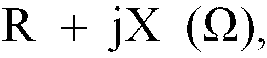


- The ratio of the number of tested detonators to the number of activated detonators is given as a test result.
- As shown in Tables 1 and 2, the explosion tests were conducted under the individual conditions as mentioned in Examples 1 to 8, and all the nine tested detonators were set off.
- In Comparative Examples 1 to 3, the
heating element 7 in the wireless detonator was changed as shown in Table 3. The other configuration of the detonator and the test conditions are the same as those in Test Example 1. The test results are shown in Table 3. - As is apparent from Table 3, eight out of nine tested detonators were set off in Comparative Example 1, while only six out of nine detonators functioned in Comparative Example 2. In Comparative Example 3, all the nine detonators misfired.
- In Comparative Example 4, the
transmission circuit 6 in the wireless detonator was changed as shown in Table 3. The other configuration of the detonator and the test conditions are the same as those in Test Example 1. The test results are also shown in Table 3. - As is apparent from Table 3, three out of the nine tested detonators were activated, the remaining detonators having failed.
- The
antenna 1, thetransmission circuit 6 and theheating element 7 in Comparative Example 5, had quite different configuration from those in Comparative Example 6 as shown in Table 4. The test conditions are the same as those in Test Example 1. - Particularly, a conventional half-wavelength dipole antenna or a conventional loop antenna (see Fig. 2) with a radiation impedance of (21 + j3) Ω and a relative gain of -0.5 dB was used as the
antenna 1. As is apparent from Table 4, nine detonators all failed in both Comparative Examples 5 and 6. - The test was conducted using the conventional initiating device shown in Fig. 3 in the same manner as in the test examples. The nine detonators all failed when the irradiation time was 5 ms.
- The test was again conducted in the same manner as before with an irradiation time of 5 seconds, and all the detonators were set off. The irradiation time until the detonation had to be set longer.


Claims (5)
- A wireless detonator including an antenna (1) for receiving microwaves, the detonator (8) including a heating element (7), and a transmission circuit (6) for connecting the antenna to the heating element to directly transmit the microwave energy from the antenna to the heating element, the wireless detonator being characterised in thatthe antenna have a relative gain of 0 to 20 dB in a microwave frequency band of 1 to 30 GHz,an absolute value of a reactance component in a radiation impedance of the antenna (1) is at most 50% of a pure resistance component of the radiation impedance,an absolute value of a reactance component in an impedance of the heating element (7) is at most 50% of a pure resistance component of the impedance, andthe pure resistance components of the radiation impedance of the antenna (1) and of the impedance of the heating element (7) are in a range of 70 to 130% of a characteristic impedance of the transmission circuit.
- A wireless detonator according to claim 1, further comprising a printed circuit board (5), the antenna and the transmission circuit being formed on the same printed circuit board.
- A wireless detonator according to claim 1, wherein the antenna (1) is a Yagi antenna.
- A wireless detonator according to claim 1, wherein the microwaves have a frequency in the range of 2.3 to 2.6 GHz.
- A wireless detonator according to claim 4, wherein the relative gain of the antenna (1) is in the range of 6 to 7 dB.
Applications Claiming Priority (2)
| Application Number | Priority Date | Filing Date | Title |
|---|---|---|---|
| JP271182/90 | 1990-10-09 | ||
| JP2271182A JPH04148199A (en) | 1990-10-09 | 1990-10-09 | Wireless primer |
Publications (2)
| Publication Number | Publication Date |
|---|---|
| EP0480673A1 EP0480673A1 (en) | 1992-04-15 |
| EP0480673B1 true EP0480673B1 (en) | 1996-01-17 |
Family
ID=17496492
Family Applications (1)
| Application Number | Title | Priority Date | Filing Date |
|---|---|---|---|
| EP91309207A Expired - Lifetime EP0480673B1 (en) | 1990-10-09 | 1991-10-08 | Wireless detonator |
Country Status (4)
| Country | Link |
|---|---|
| US (1) | US5146044A (en) |
| EP (1) | EP0480673B1 (en) |
| JP (1) | JPH04148199A (en) |
| KR (1) | KR950006011B1 (en) |
Families Citing this family (12)
| Publication number | Priority date | Publication date | Assignee | Title |
|---|---|---|---|---|
| US6152039A (en) * | 1991-09-04 | 2000-11-28 | Royal Ordnance Plc | Initiation of propellants |
| CA2103510A1 (en) * | 1992-09-11 | 1994-03-12 | Morton International Inc. | Printed circuit bridge for an airbag inflator |
| US7345552B2 (en) * | 2004-05-19 | 2008-03-18 | Nihon Dempa Kogyo Co., Ltd. | Constant temperature type crystal oscillator |
| PE20060926A1 (en) * | 2004-11-02 | 2006-09-04 | Orica Explosives Tech Pty Ltd | ASSEMBLIES OF WIRELESS DETONATORS, CORRESPONDING BLASTING APPLIANCES AND BLASTING METHODS |
| US8065959B1 (en) * | 2009-06-22 | 2011-11-29 | Shulte David J | Explosive device |
| US8104406B1 (en) | 2009-06-22 | 2012-01-31 | Shulte David J | Explosive device |
| CN103438768A (en) * | 2013-09-04 | 2013-12-11 | 融硅思创(北京)科技有限公司 | Radio frequency digital electronic detonator based on plastic detonating tube excitation |
| WO2017083885A1 (en) * | 2015-11-09 | 2017-05-18 | Detnet South Africa (Pty) Ltd | Wireless detonator |
| US10641572B1 (en) * | 2016-04-19 | 2020-05-05 | Triad National Security, Llc | Microwave ignition of energetic material housed within a gun |
| US11585622B1 (en) | 2016-04-19 | 2023-02-21 | Triad National Security, Llc | Microwave ignition systems with launcher affixed to or located within a gun spindle |
| US10107607B1 (en) * | 2017-04-04 | 2018-10-23 | The United States Of America As Represented By The Secretary Of The Army | Radio frequency igniter |
| US10969206B1 (en) * | 2018-11-29 | 2021-04-06 | U.S. Government As Represented By The Secretary Of The Army | Radio frequency antenna for use in the confines of a breech |
Family Cites Families (5)
| Publication number | Priority date | Publication date | Assignee | Title |
|---|---|---|---|---|
| JPS5741600A (en) * | 1980-08-26 | 1982-03-08 | Nippon Oils & Fats Co Ltd | Method of and apparatus for triggering percussion cap by microwave |
| JPS60111900A (en) * | 1983-11-22 | 1985-06-18 | 日本油脂株式会社 | Remote control short-dealy blasting device |
| DE3430215A1 (en) * | 1984-08-17 | 1986-02-27 | Hoechst Ag, 6230 Frankfurt | PHENOXYPROPIONIC ACID DERIVATIVES, METHOD FOR THE PRODUCTION THEREOF AND THEIR USE AS HERBICIDES |
| JPS6356480A (en) * | 1986-08-27 | 1988-03-11 | Konica Corp | Ink ribbon cassette |
| SE456939B (en) * | 1987-02-16 | 1988-11-14 | Nitro Nobel Ab | SPRAENGKAPSEL |
-
1990
- 1990-10-09 JP JP2271182A patent/JPH04148199A/en active Pending
-
1991
- 1991-10-07 US US07/773,125 patent/US5146044A/en not_active Expired - Fee Related
- 1991-10-07 KR KR1019910017520A patent/KR950006011B1/en not_active Expired - Fee Related
- 1991-10-08 EP EP91309207A patent/EP0480673B1/en not_active Expired - Lifetime
Also Published As
| Publication number | Publication date |
|---|---|
| EP0480673A1 (en) | 1992-04-15 |
| JPH04148199A (en) | 1992-05-21 |
| KR930008427A (en) | 1993-05-21 |
| US5146044A (en) | 1992-09-08 |
| KR950006011B1 (en) | 1995-06-07 |
Similar Documents
| Publication | Publication Date | Title |
|---|---|---|
| US5146044A (en) | Wireless detonator | |
| CA1089091A (en) | Portable radio antenna | |
| EP0421646A2 (en) | Transmitters and receivers with antennas | |
| US7130624B1 (en) | System and method for destabilizing improvised explosive devices | |
| US4475108A (en) | Electronically tunable microstrip antenna | |
| US4644366A (en) | Miniature radio transceiver antenna | |
| CA2067661C (en) | Digital delay detonator | |
| US5113196A (en) | Loop antenna with transmission line feed | |
| US5133257A (en) | Ignition system and a method for the initiation thereof | |
| US3176298A (en) | Attachment for antennas to reduce operating frequencies | |
| JPS6157558B2 (en) | ||
| US5837926A (en) | Mines having tuned passive electromagnetic reflectors to enhance radar detection | |
| US4848233A (en) | Means for protecting electroexplosive devices which are subject to a wide variety of radio frequency | |
| US5355800A (en) | Combined EED igniter means and means for protecting the EED from inadvertent extraneous electricity induced firing | |
| US5361702A (en) | Mechanical shielding for electric primer | |
| EP0280799B1 (en) | Antenna system for wide bandwidth signals | |
| US3508271A (en) | Folded monopole antenna | |
| Sripho et al. | Comparison of antenna for DTI rocket telemetry system | |
| US4965606A (en) | Antenna shroud tempest armor | |
| EP1143556B1 (en) | Projectile with antenna for a satellite navigation receiver | |
| US3022505A (en) | Loaded double-folded slot antenna | |
| US7434516B1 (en) | Ferroelectric transmitters for warhead design and battle damage assessment | |
| US4137819A (en) | Launch tube antenna | |
| US4195295A (en) | Pulse doppler-radio proximity fuze | |
| Heard et al. | Measurements of the field strengths on offshore oil platforms for assessing radio-frequency hazards with electroexplosive devices |
Legal Events
| Date | Code | Title | Description |
|---|---|---|---|
| PUAI | Public reference made under article 153(3) epc to a published international application that has entered the european phase |
Free format text: ORIGINAL CODE: 0009012 |
|
| AK | Designated contracting states |
Kind code of ref document: A1 Designated state(s): GB SE |
|
| 17P | Request for examination filed |
Effective date: 19920925 |
|
| 17Q | First examination report despatched |
Effective date: 19940603 |
|
| GRAA | (expected) grant |
Free format text: ORIGINAL CODE: 0009210 |
|
| RAP1 | Party data changed (applicant data changed or rights of an application transferred) |
Owner name: NOF CORPORATION |
|
| AK | Designated contracting states |
Kind code of ref document: B1 Designated state(s): GB SE |
|
| PLBE | No opposition filed within time limit |
Free format text: ORIGINAL CODE: 0009261 |
|
| STAA | Information on the status of an ep patent application or granted ep patent |
Free format text: STATUS: NO OPPOSITION FILED WITHIN TIME LIMIT |
|
| 26N | No opposition filed | ||
| PGFP | Annual fee paid to national office [announced via postgrant information from national office to epo] |
Ref country code: GB Payment date: 19991006 Year of fee payment: 9 |
|
| PGFP | Annual fee paid to national office [announced via postgrant information from national office to epo] |
Ref country code: SE Payment date: 19991007 Year of fee payment: 9 |
|
| PG25 | Lapsed in a contracting state [announced via postgrant information from national office to epo] |
Ref country code: GB Free format text: LAPSE BECAUSE OF NON-PAYMENT OF DUE FEES Effective date: 20001008 |
|
| PG25 | Lapsed in a contracting state [announced via postgrant information from national office to epo] |
Ref country code: SE Free format text: THE PATENT HAS BEEN ANNULLED BY A DECISION OF A NATIONAL AUTHORITY Effective date: 20001030 |
|
| GBPC | Gb: european patent ceased through non-payment of renewal fee |
Effective date: 20001008 |
|
| EUG | Se: european patent has lapsed |
Ref document number: 91309207.8 |