EP0480187B1 - Communication system, especially for communication satellites - Google Patents
Communication system, especially for communication satellites Download PDFInfo
- Publication number
- EP0480187B1 EP0480187B1 EP91115342A EP91115342A EP0480187B1 EP 0480187 B1 EP0480187 B1 EP 0480187B1 EP 91115342 A EP91115342 A EP 91115342A EP 91115342 A EP91115342 A EP 91115342A EP 0480187 B1 EP0480187 B1 EP 0480187B1
- Authority
- EP
- European Patent Office
- Prior art keywords
- data rate
- communication system
- modulators
- baseband
- output signals
- Prior art date
- Legal status (The legal status is an assumption and is not a legal conclusion. Google has not performed a legal analysis and makes no representation as to the accuracy of the status listed.)
- Expired - Lifetime
Links
Images
Classifications
-
- H—ELECTRICITY
- H04—ELECTRIC COMMUNICATION TECHNIQUE
- H04B—TRANSMISSION
- H04B7/00—Radio transmission systems, i.e. using radiation field
- H04B7/14—Relay systems
- H04B7/15—Active relay systems
- H04B7/204—Multiple access
- H04B7/2041—Spot beam multiple access
Definitions
- the invention relates to a communication system, in particular for communication satellites, according to the preamble of claim 1.
- a communication system is known from IEEE International Conference on Communications, Advanced Communications Technology Satellite (ACTS), pages 1566-1577.
- a disadvantage of such communication systems is that a certain capacity or data rate is allocated to each transmission beam. This capacity is usually fixed, ie it cannot be changed. However, it is quite the case that during a certain operating time demands are made on certain capacity expansions for certain beam lobes. This is done by assigning a channel with the data rate X, for example, to a beam with increased capacity requirements, but has to accept the fact that the capacity of another beam is reduced by precisely this value X, since the total capacity for which the system is aligned is, cannot be exceeded. In other words, the total capacity of the communication system is divided into a number of L channels, these channels each having the same bandwidth or the same data rate, for example. In order to change the capacity of a beam of beams, entire channels are switched. To do this Depending on the flexibility of the system, complex switching matrices and multiplexers are required, which operate in the intermediate frequency or radio frequency range.
- the invention is based on the following object of specifying a communication system of the type mentioned at the outset, which is able to meet the requirements for capacity expansion or reduction on the individual beam lobes in a flexible manner, bypassing or at least significantly reducing complex switching matrices or multiplexers in the intermediate frequency - or radio frequency range.
- the communication system according to the invention allows a very flexible handling of different capacity requirements for the transmitting beam lobes, the effort being relatively small. Especially when using digital modulators, the effort is significantly reduced and a high degree of flexibility is achieved.
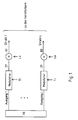
- Figures 1 and 2 show block diagrams for embodiments of the communication system according to the invention.
- the switching device VE in each case arranged on the left, and the outgoing lines with modulated data signals leading to the amplifiers and are assigned to the individual beam lobes 1 to L, arranged on the right.
- the switching device has a plurality of data outputs 1 to L which are to be emitted by the individual beam lobes of the multi-beam transmitting antenna and which each have a variable output data rate according to the invention.
- This variability can, for example, take place continuously or in certain steps.
- the switchover should be implemented in steps of, for example, 8.16, 32.48 and 64 Mbit / s. If one disregards the fact that individual data streams or message streams are pending simultaneously at several outputs and can thus be received simultaneously in several area zones illuminated by the individual beam lobes, the data rate at one or more outputs increases with a corresponding reduction in the data rate at one or several other outputs so that the total throughput of the switching device remains constant.
- the output data of the switching device are then each fed to a modulator whose modulation data rate is variable and which is adapted to the data rate of the output concerned.
- Tunable filters are inserted at the input and or at the output of each modulator, the characteristics of which must also be adapted to the respective data rate.
- the tunable filters are not shown in Figure 1.
- the output frequency of the modulators is in the intermediate frequency range or possibly also the transmission frequency. If the latter is the case, a change in the carrier frequency must also be carried out when the data rate changes, so that the transmitted spectrum does not Limits of the band available for the satellite are violated.
- variable local oscillator carrier frequency must be fed to the subsequent up-mixer in a corresponding manner.
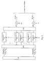
- the outputs 1 to L of the switching device according to FIG. 2 do not have continuously variable data rates, but rather data rates that can be set in certain steps. You could now also assign the same number of L modulators in each case according to FIG. 1, their modulation data rates having to be variably adapted and set accordingly. Another variant would also be conceivable, namely to make the modulation data rates of these subsequent modulators also gradually adjustable in a manner corresponding to the outputs of the switching device.
- the implementation with modulators with a fixed but different data rate, which are switched accordingly, according to FIG. 2 is suitable for higher-rate systems for which no digital modulators are yet available.
- filters which can be tuned are inserted before and or behind the switching matrices SM 1 and SM 2, the characteristics of which must be adapted to the respective data rate.
- the filters can also be installed in the signal branch between the switching matrix SM 1 and switching matrix SM 2 in front of or behind the individual modulators, appropriately adapted to the respective data rate of the modulator in question.
Abstract
Description
Die Erfindung bezieht sich auf ein Kommunikationssystem, insbesondere für Kommunikationssatelliten, gemäß Oberbegriff des Anspruchs 1. Ein solches Kommunikationssystem ist aus IEEE International Conference on Communications, Advanced Communications Technology Satellite (ACTS), Seiten 1566-1577 bekannt.The invention relates to a communication system, in particular for communication satellites, according to the preamble of
Nachteilig ist bei solchen Kommunikationssytemen, daß jeder Sendestrahlenkeule eine gewisse Kapazität bzw. Datenrate zugeteilt wird. Diese Kapazität ist zumeist fix, d.h. kann nicht verändert werden. Es ist aber durchaus so, daß während einer gewissen Betriebszeit Anforderungen an gewisse Kapazitätserweiterungen bei bestimmten Strahlenkeulen gestellt werden. Man behilft sich so, daß einer Strahlenkeule mit erhöhter Kapazitätsanforderung ein Kanal mit der Datenrate beispielsweise X zugeordnet wird, muß aber in Kauf nehmen, daß einem anderen Keulenstrahl die Kapazität um eben diesen Wert X reduziert wird, da die Gesamtkapazität, für die das System ausgerichtet ist, nicht überschrittten werden kann. D.h. mit anderen Worten, die Gesamtkapazität des Kommunikationssystem wird in eine Anzahl L-Kanäle aufgeteilt, wobei diese Kanäle beispielsweise jeweils die gleiche Bandbreite bzw. gleiche Datenrate aufweisen. Um die Kapazität eines Keulenstrahls zu ändern, werden also komplette Kanäle umgeschaltet. Dazu sind je nach Flexibilität des Systems aufwendige Schaltmatritzen und Multiplexer notwendig, welche im Zwischenfrequenz- oder Radiofrequenzbereich arbeiten.A disadvantage of such communication systems is that a certain capacity or data rate is allocated to each transmission beam. This capacity is usually fixed, ie it cannot be changed. However, it is quite the case that during a certain operating time demands are made on certain capacity expansions for certain beam lobes. This is done by assigning a channel with the data rate X, for example, to a beam with increased capacity requirements, but has to accept the fact that the capacity of another beam is reduced by precisely this value X, since the total capacity for which the system is aligned is, cannot be exceeded. In other words, the total capacity of the communication system is divided into a number of L channels, these channels each having the same bandwidth or the same data rate, for example. In order to change the capacity of a beam of beams, entire channels are switched. To do this Depending on the flexibility of the system, complex switching matrices and multiplexers are required, which operate in the intermediate frequency or radio frequency range.
Aus der US-A-4,858,225 ist es an sich bekannt, in einem Kommunikationssystem mit Basisbandvermittlung und Mehrstrahlantenne variable Datenraten mittels "on board switching" je nach Verkehrsaufkommen zu generieren.From US-A-4,858,225 it is known per se to generate variable data rates in a communication system with baseband switching and multi-beam antenna by means of "on board switching" depending on the traffic volume.
Der Erfindung liegt folgende Aufgabe zugrunde, ein Kommunikationssystem der eingangs genannten Art anzugeben, welches in der Lage ist, Anforderungen nach Kapazitätserweiterung oder -erniedrigung auf den einzelnen Strahlenkeulen in flexibler Weise nachzukommen unter Umgehung von oder zumindest mit deutlicher Reduzierung von aufwendigen Schaltmatritzen oder Multiplexern im Zwischenfrequenz- oder Radiofrequenzbereich.The invention is based on the following object of specifying a communication system of the type mentioned at the outset, which is able to meet the requirements for capacity expansion or reduction on the individual beam lobes in a flexible manner, bypassing or at least significantly reducing complex switching matrices or multiplexers in the intermediate frequency - or radio frequency range.
Die Lösung erfolgt durch die kennzeichnenden Merkmale des Anspruches 1.The solution is achieved by the characterizing features of
Vorteilhafte Ausgestaltungen ergeben sich durch die Unteransprüche.Advantageous refinements result from the subclaims.
Das erfindungsgemäße Kommunikationssystem erlaubt eine sehr flexible Handhabung unterschiedlicher Kapazitätsanforderungen an die Sendestrahlenkeulen, wobei der Aufwand relativ klein ist. Vor allem bei Verwendung digitaler Modulatoren wird der Aufwand deutlich gesenkt, und es wird eine hohe Flexibilität erreicht.The communication system according to the invention allows a very flexible handling of different capacity requirements for the transmitting beam lobes, the effort being relatively small. Especially when using digital modulators, the effort is significantly reduced and a high degree of flexibility is achieved.
Es folgt nun die Beschreibung der Erfindung anhand der Figuren.
Die Figuren 1 und 2 zeigen Blockschaltbilder für Ausführungsformen des erfindungsgemäßen Kommunikationssystem.There now follows the description of the invention with reference to the figures.
Figures 1 and 2 show block diagrams for embodiments of the communication system according to the invention.
Bei den Figuren ist gemeinsam die Vermittlungseinrichtung VE, jeweils links angeordnet, und die abgehenden Leitungen mit modulierten Datensignalen, die zu den Verstärkern führen und den einzelnen Strahlenkeulen 1 bis L zugeordnet sind, rechts angeordnet.In the figures, the switching device VE, in each case arranged on the left, and the outgoing lines with modulated data signals leading to the amplifiers and are assigned to the
Die Vermittlungseinrichtung nach Figur 1 weist mehrere Datenausgänge 1 bis L auf, die zur Ausstrahlung durch die einzelnen Strahlenkeulen der Mehrstrahlsendeantenne anstehen, und die jeweils erfindungsgemäß eine variable Ausgangsdatenrate aufweisen. Diese Variabilität kann beispielsweise stufenlos oder in bestimmten Stufen erfolgen. In der Praxis dürfte die Umschaltung in Stufen von beispielsweise 8,16,32,48 und 64 Mbit/s realisiert sein. Wenn man davon absieht, daß einzelne Datenströme oder Nachrichtenströme gleichzeitig an mehreren Ausgängen anstehen und damit gleichzeitig in mehreren von den einzelnen Strahlenkeulen beleuchteten Gebietszonen empfangen werden können, so geht eine Erhöhung der Datenrate an einem oder mehreren Ausgängen mit einer entsprechenden Verringerung der Datenrate an einem oder mehreren anderen Ausgängen einher, damit der Gesamtdurchsatz der Vermittlungseinrichtung an Daten konstant bleibt. Die Ausgangsdaten der Vermittlungseinrichtung werden anschließend jeweils einem Modulator zugeführt, dessen Modulationsdatenrate variabel ist und der Datenrate des betreffenden Ausgangs angepaßt wird. Am Eingang und oder am Ausgang jedes Modulators sind abstimmbare Filter eingefügt, deren Charakteristik ebenfalls der jeweiligen Datenrate anzupassen ist. Die abstimmbaren Filter sind in Figur 1 nicht gezeichnet.The switching device according to FIG. 1 has a plurality of
Je nach verfügbarer Technologie ist die Ausgangsfrequenz der Modulatoren im Zwischenfrequenzbereich oder eventuell auch die Sendefrequenz. Ist das Letztere der Fall, so ist bei einer Änderung der Datenrate auch eine Änderung der Trägerfrequenz durchzuführen, so daß mit dem gesendeten Spektrum nicht die Grenzen des für den Satelliten verfügbaren Bandes verletzt werden.Depending on the technology available, the output frequency of the modulators is in the intermediate frequency range or possibly also the transmission frequency. If the latter is the case, a change in the carrier frequency must also be carried out when the data rate changes, so that the transmitted spectrum does not Limits of the band available for the satellite are violated.
Ist die Ausgangsfrequenz des Modulators im Zwischenfrequenzbereich, wie in Figur 1 gezeichnet, so muß in entsprechender Weise dem nachfolgenden Aufwärtsmischer eine variable Lokaloszillator Trägerfrequenz zugeführt werden.If the output frequency of the modulator is in the intermediate frequency range, as shown in FIG. 1, a variable local oscillator carrier frequency must be fed to the subsequent up-mixer in a corresponding manner.
Bei Einsatz der gegenwärtig zur Verfügung stehenden Halbleitertechnik bieten sich für Datenraten bis etwa 20 Mbit/s für den Modulator vorteilhafterweise vollständig digitalisierte Lösungen an. Bei höheren Datenraten müssen aus heutiger Sicht analoge Modulatoren verwendet werden.When using the semiconductor technology currently available, fully digitized solutions are advantageously available for data rates of up to approximately 20 Mbit / s for the modulator. From today's perspective, analog modulators must be used for higher data rates.
Im Gegensatz zu der Ausführungsform nach Figur 1 weisen die Ausgänge 1 bis L der Vermittlungseinrichtung nach Figur 2 nicht stufenlos variable Datenraten, sondern in bestimmten Stufen einstellbare Datenraten auf. Ihnen könnte man nun nach Figur 1 ebenfalls die gleiche Anzahl von L-Modulatoren jeweils fest zuordnen, wobei ihre Modulationsdatenraten variabel entsprechend angepaßt und eingestellt werden müssen. Auch eine andere Variante wäre denkbar, nämlich die Modulationsdatenraten dieser nachfolgenden Modulatoren ebenfalls stufenweise einstellbar zu gestalten in entsprechender Weise wie die Ausgänge der Vermittlungseinrichtung.In contrast to the embodiment according to FIG. 1, the
Beide Lösungen sind in Figur 2 nicht gezeichnet, vielmehr sind eine Anzahl N Modulatoren mit der Modulationsdatenrate R1, eine Anzahl M Modulatoren mit der Datenrate R2 usw. und ein Modulator mit der Modulationsdatenrate Rn vorgesehen, welche mittels einer Schaltmatrix SM 1 auf die Ausgänge mit der entsprechenden Datenrate aufgeschaltet werden können. Mittels einer weiteren Schaltmatrix SM 2 sind die Modulatorausgänge in entsprechend vorgegebener Weise auf die Signalzweige zu den einzelnen Strahlenkeulen der Mehrstrahlantenne schaltbar.Both solutions are not shown in FIG. 2, rather a number N modulators with the modulation data rate R1, a number M modulators with the data rate R2 etc. and a modulator with the modulation data rate R n are provided, which are connected to the outputs by means of a
Die Realisierung mit Modulatoren mit fester aber unterschiedlicher Datenrate, die entsprechend geschaltet werden, gemäß Figur 2 bietet sich für höherratige Systeme an, für welche noch keine digitale Modulatoren verfügbar sind.The implementation with modulators with a fixed but different data rate, which are switched accordingly, according to FIG. 2 is suitable for higher-rate systems for which no digital modulators are yet available.
In entsprechender Weise wie bei dem Blockschaltbild nach Figur 1 sind unter Umständen vor und oder hinter den Schaltmatrizen SM 1 und SM 2 abstimmbare Filter einzufügen, deren Charakteristik der jeweiligen Datenrate anzupassen ist. Die Filter können aber auch im Signalzweig zwischen Schaltmatrix SM 1 und Schaltmatrix SM 2 vor und oder hinter den Einzelmodulatoren, entsprechend angepaßt an die jeweiligen Datenrate des betreffenden Modulators fest voreingestellt installiert sein.In a manner corresponding to the block diagram according to FIG. 1, filters which can be tuned are inserted before and or behind the
Claims (8)
- Communication system, in particular for communication satellites with baseband switching and multibeam antenna, having variable allocation of transmission capacity to the individual transmit beam lobes (1...L), the individual baseband output signals being combined in accordance with their current data rate with modulators of the corresponding modulation data rates and being modulated by means of these modulators onto respectively one carrier frequency, and it being possible for the baseband output signals to be converted into an intermediate frequency band (ZF) by means of the modulators, characterized in that the baseband output signals of a switching device (VE) which are assigned in the individual transmit beam lobes have a variable data rate, and in that in order to convert the signals of the intermediate frequency band (ZF) into the radio-frequency range (RF), mixers are provided to which carriers (Lo) with a variably settable frequency can be fed.
- Communication system according to Claim 1, characterized in that the data rate of the baseband output signals can be set or switched over to a number of permanently prescribed values (R₁, R₂ ... RN).
- Communication system according to Claim 1 or 2, characterized in that each baseband output is permanently assigned a modulator whose modulation data rate is variable and is respectively matched to that of the relevant baseband output.
- Communication system according to Claim 2, characterized in that a number of modulators with a corresponding modulation rate are provided for each prescribed value of the data rate.
- Communication system according to Claim 4, characterized in that the modulators can be connected by means of switches or a switching matrix (SM1) to the baseband outputs which have the same data rates.
- Communication system according to Claim 5, characterized in that further switches or a further switching matrix (SM2) are provided by means of which the modulators can be assigned to the individual transmit beam lobes (1...L) or can be connected to the latter.
- Communication system according to one of the preceding claims, characterized in that filters whose characteristic can be set in accordance with the current data rate are provided for pulse shaping of the baseband output signals.
- Communication system according to one of the preceding claims, characterized in that the output power of the modulators can be set in a manner proportional to the data rate.
Applications Claiming Priority (2)
| Application Number | Priority Date | Filing Date | Title |
|---|---|---|---|
| DE4032262 | 1990-10-11 | ||
| DE4032262A DE4032262C1 (en) | 1990-10-11 | 1990-10-11 |
Publications (3)
| Publication Number | Publication Date |
|---|---|
| EP0480187A2 EP0480187A2 (en) | 1992-04-15 |
| EP0480187A3 EP0480187A3 (en) | 1992-05-13 |
| EP0480187B1 true EP0480187B1 (en) | 1995-12-06 |
Family
ID=6416076
Family Applications (1)
| Application Number | Title | Priority Date | Filing Date |
|---|---|---|---|
| EP91115342A Expired - Lifetime EP0480187B1 (en) | 1990-10-11 | 1991-09-11 | Communication system, especially for communication satellites |
Country Status (3)
| Country | Link |
|---|---|
| EP (1) | EP0480187B1 (en) |
| AT (1) | ATE131326T1 (en) |
| DE (1) | DE4032262C1 (en) |
Families Citing this family (1)
| Publication number | Priority date | Publication date | Assignee | Title |
|---|---|---|---|---|
| DE19620843B4 (en) * | 1996-05-23 | 2005-08-11 | Siemens Ag | Modulation carrier modulation method and mobile communication system |
Family Cites Families (2)
| Publication number | Priority date | Publication date | Assignee | Title |
|---|---|---|---|---|
| US4858225A (en) * | 1987-11-05 | 1989-08-15 | International Telecommunications Satellite | Variable bandwidth variable center-frequency multibeam satellite-switched router |
| JPH0648796B2 (en) * | 1988-02-05 | 1994-06-22 | 日本電気株式会社 | Demand assign satellite communication device |
-
1990
- 1990-10-11 DE DE4032262A patent/DE4032262C1/de not_active Expired - Lifetime
-
1991
- 1991-09-11 EP EP91115342A patent/EP0480187B1/en not_active Expired - Lifetime
- 1991-09-11 AT AT91115342T patent/ATE131326T1/en not_active IP Right Cessation
Also Published As
| Publication number | Publication date |
|---|---|
| EP0480187A2 (en) | 1992-04-15 |
| ATE131326T1 (en) | 1995-12-15 |
| EP0480187A3 (en) | 1992-05-13 |
| DE4032262C1 (en) | 1992-03-12 |
Similar Documents
| Publication | Publication Date | Title |
|---|---|---|
| EP0139034B1 (en) | Process for the transmission of information services by satellites | |
| EP0951788B1 (en) | Arrangement for radio transmission of digital data in a radio network | |
| EP0210698B1 (en) | Radio transmission system with a variable time slot duration in a time division multiplex frame | |
| DE69113251T3 (en) | REMOTE RECEIVER. | |
| DE3919352A1 (en) | VARIABLE BANDWIDTH AND VARIABLE CENTER FREQUENCY SWITCHING OF A SATELLITE SWITCHED SIGNAL DISTRIBUTOR | |
| DE69933622T2 (en) | A time division multiplex approach for broadcasting with multiple transmitters | |
| DE2844776C2 (en) | Transmitter system for a communication system with moving participants | |
| DE19731475A1 (en) | Communication network node with channeling switching matrix architecture | |
| DE2811576A1 (en) | ARRANGEMENT FOR CONVERTING DISCRETE SIGNALS INTO A DISCRETE SINGLE-SIDEBAND FREQUENCY MULTIPLEX SIGNAL AND VICE VERSA | |
| EP0890271B1 (en) | Point-multipoint radio transmission system | |
| EP0866629B1 (en) | One-to-many-points radio transmission system | |
| DE1466146A1 (en) | Transceiver device for the transmission of messages subject to the Doppler effect | |
| EP0480187B1 (en) | Communication system, especially for communication satellites | |
| DE2316166B2 (en) | Community antenna system with alarm devices for the individual participants | |
| DE3729585C2 (en) | ||
| EP0612460B1 (en) | Method for radio transmission using a fixed base station and a plurality of independent fixed subscriber stations | |
| EP0765095A2 (en) | Method for allocating radio resources to different base station transmitting equipment in a radio communication system | |
| DE60031225T2 (en) | Routing in a satellite communication system | |
| DE4034979A1 (en) | MESSAGE SYSTEM FOR BIDIRECTIONAL MESSAGE TRANSMISSION BETWEEN GROUND STATIONS WITH THE HELP OF A MESSAGE SATELLITE | |
| DE69626905T2 (en) | Satellite repeater for switching radio lobes of channels and subchannels | |
| DE3824338C2 (en) | ||
| EP1024607B1 (en) | Multichannel radio transmission system | |
| DE19635533A1 (en) | Point-to-multipoint transmission system | |
| DE19737758A1 (en) | Method for setting the transmission carrier frequency in a subscriber station of a point-to-multipoint radio transmission system | |
| DE60221314T2 (en) | Resource allocation method in a frequency-hopped wireless network |
Legal Events
| Date | Code | Title | Description |
|---|---|---|---|
| PUAI | Public reference made under article 153(3) epc to a published international application that has entered the european phase |
Free format text: ORIGINAL CODE: 0009012 |
|
| PUAL | Search report despatched |
Free format text: ORIGINAL CODE: 0009013 |
|
| AK | Designated contracting states |
Kind code of ref document: A2 Designated state(s): AT CH FR GB IT LI |
|
| AK | Designated contracting states |
Kind code of ref document: A3 Designated state(s): AT CH FR GB IT LI |
|
| 17P | Request for examination filed |
Effective date: 19920925 |
|
| 17Q | First examination report despatched |
Effective date: 19940913 |
|
| GRAA | (expected) grant |
Free format text: ORIGINAL CODE: 0009210 |
|
| AK | Designated contracting states |
Kind code of ref document: B1 Designated state(s): AT CH FR GB IT LI |
|
| REF | Corresponds to: |
Ref document number: 131326 Country of ref document: AT Date of ref document: 19951215 Kind code of ref document: T |
|
| ET | Fr: translation filed | ||
| REG | Reference to a national code |
Ref country code: CH Ref legal event code: NV Representative=s name: SCINTILLA AG, DIREKTION |
|
| ITF | It: translation for a ep patent filed |
Owner name: STUDIO JAUMANN |
|
| GBT | Gb: translation of ep patent filed (gb section 77(6)(a)/1977) |
Effective date: 19960213 |
|
| PGFP | Annual fee paid to national office [announced via postgrant information from national office to epo] |
Ref country code: GB Payment date: 19960827 Year of fee payment: 6 |
|
| PGFP | Annual fee paid to national office [announced via postgrant information from national office to epo] |
Ref country code: FR Payment date: 19960917 Year of fee payment: 6 |
|
| PGFP | Annual fee paid to national office [announced via postgrant information from national office to epo] |
Ref country code: AT Payment date: 19960919 Year of fee payment: 6 |
|
| PGFP | Annual fee paid to national office [announced via postgrant information from national office to epo] |
Ref country code: CH Payment date: 19960924 Year of fee payment: 6 |
|
| PLBE | No opposition filed within time limit |
Free format text: ORIGINAL CODE: 0009261 |
|
| STAA | Information on the status of an ep patent application or granted ep patent |
Free format text: STATUS: NO OPPOSITION FILED WITHIN TIME LIMIT |
|
| 26N | No opposition filed | ||
| PG25 | Lapsed in a contracting state [announced via postgrant information from national office to epo] |
Ref country code: GB Free format text: LAPSE BECAUSE OF NON-PAYMENT OF DUE FEES Effective date: 19970911 Ref country code: AT Free format text: LAPSE BECAUSE OF NON-PAYMENT OF DUE FEES Effective date: 19970911 |
|
| PG25 | Lapsed in a contracting state [announced via postgrant information from national office to epo] |
Ref country code: LI Free format text: LAPSE BECAUSE OF NON-PAYMENT OF DUE FEES Effective date: 19970930 Ref country code: FR Free format text: THE PATENT HAS BEEN ANNULLED BY A DECISION OF A NATIONAL AUTHORITY Effective date: 19970930 Ref country code: CH Free format text: LAPSE BECAUSE OF NON-PAYMENT OF DUE FEES Effective date: 19970930 |
|
| GBPC | Gb: european patent ceased through non-payment of renewal fee |
Effective date: 19970911 |
|
| REG | Reference to a national code |
Ref country code: CH Ref legal event code: PL |
|
| REG | Reference to a national code |
Ref country code: FR Ref legal event code: ST |
|
| PG25 | Lapsed in a contracting state [announced via postgrant information from national office to epo] |
Ref country code: IT Free format text: LAPSE BECAUSE OF NON-PAYMENT OF DUE FEES;WARNING: LAPSES OF ITALIAN PATENTS WITH EFFECTIVE DATE BEFORE 2007 MAY HAVE OCCURRED AT ANY TIME BEFORE 2007. THE CORRECT EFFECTIVE DATE MAY BE DIFFERENT FROM THE ONE RECORDED. Effective date: 20050911 |