EP0480087A1 - Low frequency loudspeaker system - Google Patents
Low frequency loudspeaker system Download PDFInfo
- Publication number
- EP0480087A1 EP0480087A1 EP90119419A EP90119419A EP0480087A1 EP 0480087 A1 EP0480087 A1 EP 0480087A1 EP 90119419 A EP90119419 A EP 90119419A EP 90119419 A EP90119419 A EP 90119419A EP 0480087 A1 EP0480087 A1 EP 0480087A1
- Authority
- EP
- European Patent Office
- Prior art keywords
- acoustic pipe
- air chamber
- low sound
- loudspeaker
- loudspeaker system
- Prior art date
- Legal status (The legal status is an assumption and is not a legal conclusion. Google has not performed a legal analysis and makes no representation as to the accuracy of the status listed.)
- Withdrawn
Links
- 230000011514 reflex Effects 0.000 claims abstract description 27
- 238000005192 partition Methods 0.000 claims description 13
- 230000002238 attenuated effect Effects 0.000 description 4
- 238000009434 installation Methods 0.000 description 4
- 230000000694 effects Effects 0.000 description 3
- 238000001914 filtration Methods 0.000 description 3
- 230000005855 radiation Effects 0.000 description 2
- 230000001419 dependent effect Effects 0.000 description 1
Images


Classifications
-
- H—ELECTRICITY
- H04—ELECTRIC COMMUNICATION TECHNIQUE
- H04R—LOUDSPEAKERS, MICROPHONES, GRAMOPHONE PICK-UPS OR LIKE ACOUSTIC ELECTROMECHANICAL TRANSDUCERS; DEAF-AID SETS; PUBLIC ADDRESS SYSTEMS
- H04R1/00—Details of transducers, loudspeakers or microphones
- H04R1/20—Arrangements for obtaining desired frequency or directional characteristics
- H04R1/22—Arrangements for obtaining desired frequency or directional characteristics for obtaining desired frequency characteristic only
- H04R1/28—Transducer mountings or enclosures modified by provision of mechanical or acoustic impedances, e.g. resonator, damping means
- H04R1/2807—Enclosures comprising vibrating or resonating arrangements
- H04R1/2853—Enclosures comprising vibrating or resonating arrangements using an acoustic labyrinth or a transmission line
- H04R1/2857—Enclosures comprising vibrating or resonating arrangements using an acoustic labyrinth or a transmission line for loudspeaker transducers
-
- H—ELECTRICITY
- H04—ELECTRIC COMMUNICATION TECHNIQUE
- H04R—LOUDSPEAKERS, MICROPHONES, GRAMOPHONE PICK-UPS OR LIKE ACOUSTIC ELECTROMECHANICAL TRANSDUCERS; DEAF-AID SETS; PUBLIC ADDRESS SYSTEMS
- H04R1/00—Details of transducers, loudspeakers or microphones
- H04R1/20—Arrangements for obtaining desired frequency or directional characteristics
- H04R1/22—Arrangements for obtaining desired frequency or directional characteristics for obtaining desired frequency characteristic only
- H04R1/28—Transducer mountings or enclosures modified by provision of mechanical or acoustic impedances, e.g. resonator, damping means
- H04R1/2807—Enclosures comprising vibrating or resonating arrangements
- H04R1/2815—Enclosures comprising vibrating or resonating arrangements of the bass reflex type
- H04R1/2819—Enclosures comprising vibrating or resonating arrangements of the bass reflex type for loudspeaker transducers
-
- H—ELECTRICITY
- H04—ELECTRIC COMMUNICATION TECHNIQUE
- H04R—LOUDSPEAKERS, MICROPHONES, GRAMOPHONE PICK-UPS OR LIKE ACOUSTIC ELECTROMECHANICAL TRANSDUCERS; DEAF-AID SETS; PUBLIC ADDRESS SYSTEMS
- H04R1/00—Details of transducers, loudspeakers or microphones
- H04R1/20—Arrangements for obtaining desired frequency or directional characteristics
- H04R1/22—Arrangements for obtaining desired frequency or directional characteristics for obtaining desired frequency characteristic only
- H04R1/28—Transducer mountings or enclosures modified by provision of mechanical or acoustic impedances, e.g. resonator, damping means
- H04R1/2807—Enclosures comprising vibrating or resonating arrangements
- H04R1/2838—Enclosures comprising vibrating or resonating arrangements of the bandpass type
- H04R1/2842—Enclosures comprising vibrating or resonating arrangements of the bandpass type for loudspeaker transducers
Definitions
- the acoustic pipe is adapted to communicate with the air chamber via an aperture of the acoustic pipe. Therefore, high sound components generated by the loudspeaker unit are attenuated by the filtering effect of the air chamber.
- sounds radiated from the back side 2a of the loudspeaker unit 2 and guided via the acoustic pipe 4 to the aperture 8 formed at the other end 4c have low sound components, at the aperture 8, of approximately the opposite phase to the phase at the back side 2a and of approximately the same frequency where the half wavelength stands in the acoustic pipe 4 of the low sound loudspeaker system.
Abstract
A low sound loudspeaker system (1) constructed of an acoustic pipe (3) extending from the back side of a loudspeaker unit, an air chamber (5) provided at the front side of the loudspeaker unit, and a bass reflex port (6) provided within the air chamber. The acoustic pipe communicates with the air chamber via the aperture (8) of the acoustic pipe.
Description
- The present invention is related to low sound loudspeaker systems.
- There are known conventional low sound loudspeaker systems such as disclosed in USP No. 4,064,966, USP No. 4,628,528, and Japanese Laid-Open No. 63-120586.
- Figs. 1A and 1B show examples of the structure of above-described prior art loudspeaker systems.
- Above-described prior art loudspeaker systems have a disadvantage that unnecessary high sounds in an acoustic pipe leak out of an aperture.
- Furthermore, in above-described prior art low sound loudspeaker systems, the loudspeaker unit is disposed facing in the direction indicated by arrow F same as that of the sound radiation direction of the system. Accordingly, as exemplary shown in Fig. 1 B, the thickness t of the cabinet is dependent upon the diameter d of the loudspeaker unit so that there is associated with a difficulty in providing a compact low sound loudspeaker system to be mounted on a vehicle.
- The present invention has been made in consideration of the above problems.
- It is therefore an object of the present invention to provide low sound loudspeaker systems capable of further attenuating unnecessary high sound components.
- It is a further object of this invention to provide low sound loudspeaker systems capable of making small the thickness of a cabinet and mounting the loudspeaker system on a vehicle.
- According to a first aspect of this invention, the low sound loudspeaker system is constructed of an acoustic pipe extending from the back side of a loudspeaker unit, an air chamber provided at the front side of the loudspeaker unit, and a bass reflex port provided within the air chamber, the acoustic pipe communicating with the air chamber via the aperture of the acoustic pipe.
- In this system, the resonance frequency of the bass reflex port is set at substantially the same frequency where the half wavelength stands in the acoustic pipe.
- According to this invention, the acoustic pipe is adapted to communicate with the air chamber via an aperture of the acoustic pipe. Therefore, high sound components generated by the loudspeaker unit are attenuated by the filtering effect of the air chamber.
- Furthermore, the resonance frequency of the bass reflect port is set substantially at the same frequency where the half wavelength stands in the acoustic pipe. Therefore, sounds radiated at the front side of the loudspeaker unit become in phase with sounds radiated from the backside of the loudspeaker unit, at the area composed of the air chamber and the port.
- Since the air chamber and the port constitute a bass reflex type loudspeaker, low sound components are radiated efficiently to the outside.
- According to a second aspect of this invention, in the low sound loudspeaker system constructed as above, a partition plate for defining the air chamber and acoustic pipe is provided, and the partition plate forms an inner and upper surface of the acoustic pipe at the area from one end to the other end of the acoustic pipe.
- In the low sound loudspeaker system constructed as above, the acoustic pipe is mounted at the outside of the loudspeaker enclosure, and is made flexible.
- Furthermore, the direction of radiating sounds from the loudspeaker unit differs approximately 90 degrees from the direction of the bass reflex port.
- The resonance frequency of the bass reflex port is set at substantially the same frequency where the half wavelength stands in the acoustic pipe.
- According to the structure of the second aspect of this invention, a partition plate for defining the air chamber and acoustic pipe is provided, and the partition plate forms an inner and upper surface of the acoustic pipe at the area from one end to the other end of the acoustic pipe. It is therefore possible to make compact the cabinet.
- The acoustic pipe is mounted at the outside of the loudspeaker enclosure, and is made flexible. It is therefore possible to make compact the cabinet. Since the acoustic pipe is flexible, the degree of freedom of installation can be improved.
- Furthermore, the resonance frequency of the bass reflect port is set substantially at the same frequency where the half wavelength stands in the acoustic pipe. Therefore, sounds radiated at the front side of the loudspeaker unit become in phase with sounds radiated from the backside of the loudspeaker unit, at the area composed of the air chamber and the port.
- Since the air chamber and the port constitute a bass reflex type loudspeaker, low sound components are radiated efficiently to the outside.
-
- Fig. 1 shows the structure of a conventional low sound loudspeaker system;
- Fig. 2 shows the structure of a first embodiment of this invention;
- Fig. 3 shows the structure of a second embodiment of this invention;
- Fig. 4 shows the structure of a third embodiment of this invention;
- Fig. 5 shows the structure of a fourth embodiment of this invention; and
- Fig. 6 to 8 show the structure of a fifth embodiment of this invention
- A first embodiment of a low sound loudspeaker system of this invention is shown in Fig. 2.
- In Fig. 2,
reference numeral 1 represents a loudspeaker enclosure, 2 a loudspeaker unit, 3 an acoustic pipe extending from theback 2a of theloudspeaker unit front side 2b of theloudspeaker unit 2, 6 a port making theair chamber 5 in communication with theoutside 7 of theloudspeaker enclosure acoustic pipe 3 at which theacoustic pipe 3 communicates with theair chamber 5. - The resonance frequency of the
port 6 is set at substantially the same frequency where the half wavelength stands in theacoustic pipe 3. - In the low sound loudspeaker system constructed as above, a bass reflex type loudspeaker system B constructed of the
Air chamber 5 and theport 6 is provided at thefront side 2b of theloudspeaker unit 2. Therefore, sounds radiated from thefront side 2b of theloudspeaker unit 2 and introduced into theair chamber 5 are outputted to the outside 7 of theloudspeaker enclosure 1, having low sound components of approximately the opposite phase and near at the resonance frequency of theport 6. - In the meantime, sounds radiated from the
back side 2a of theloudspeaker unit 2 and guided via theacoustic pipe 3 to theaperture 8 have low sound components, at theaperture 8, of approximately the opposite phase to the phase at theback side 2a and of approximately the frequency where the half wavelength stands in theacoustic pipe 3 of the low sound loudspeaker system. - Sounds passed through the
acoustic pipe 3 are also introduced in the bass reflex type loudspeaker system B. In this bass reflex type loudspeaker system B, sounds from thefront side 2b of theloudspeaker unit 2 and those from theback side 2a are added together, reproducing low sound components more efficiently. - Reproduction efficiency is improved considerably because of the structure that the resonance frequency of the
port 6 is set at substantially the same frequency where the half wavelength stands in theacoustic pipe 3. - Sounds radiated into the
acoustic pipe 3 are most emphasized at the frequency where the wavelength is two times as long as the length of theacoustic pipe 3, and radiated into the outside (air chamber 5) of theaperture 8. Sounds having a different frequency whose wavelength is a multiple in odd number of the length of theacoustic pipe 3 are also radiated in the outside of theaperture 3. In this case, however, such sounds have at theaperture 8 the opposite phase to that at thefront side 2b so that they are canceled by the sounds at thefront side 2b of theloudspeaker unit 2, whereas other sounds are introduced into theair chamber 5. Consequently, high sound components are efficiently attenuated by the filtering effect of theair chamber 5. - Furthermore, since the
air chamber 5 and theacoustic pipe 3 are communicated with each other via theaperture 8, the equivalent length of theacoustic pipe 3 becomes longer and the equivalent volume of theair chamber 5 becomes large, thereby broadening the low sound bandwidth. - Figs. 3 and 4 show the second and third embodiments of this invention. In the embodiment shown in Fig. 3,
partition plates 4A are disposed to form twoacoustic pipes apertures acoustic pipes air chamber 5 are communicated with each other. - In the embodiment shown in Fig. 4, there are provided two
loudspeaker units acoustic pipes acoustic pipes air chamber 5 viacorresponding apertures - In the embodiments shown in Figs. 3 and 4, the length of the
acoustic pipes - According to the above embodiments, in a low sound loudspeaker constructed of an acoustic pipe extending from the back side of the loudspeaker unit, an air chamber formed at the front side of the loudspeaker unit, and a bass reflex port provided in the air chamber, the acoustic pipe is adapted to communicate with the air chamber via an aperture of the acoustic pipe. Therefore, high sound components generated by the loudspeaker unit are attenuated by the filtering effect of the air chamber.
- Furthermore, the resonance frequency of the bass reflex port is set substantially at the same frequency where the half wavelength stands in the acoustic pipe. Therefore, sounds radiated at the front side of the loudspeaker unit become in phase with sounds radiated from the backside of the loudspeaker unit, at the area composed of the air chamber and the port.
- Since the air chamber and the port constitute a bass reflex type loudspeaker, low sound components are radiated efficiently to the outside.
- In summary, the advantages of the embodiments of this invention shown in Figs. 2 to 4 are as follows:
- (1) unnecessary high sound components can be considerably attenuated;
- (2) reproduction efficiency of low sounds can be improved; and
- (3) since an opening of the loudspeaker system is only one, the freedom of location thereof can be improved.
- Furthermore, the system of this invention is simple in structure and cost effective, allowing easy installation.
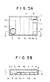
- Figs. 5A and 5B, show the fourth embodiment, wherein Fig. 5A is a sectional view and Fig. 5B is a sectional view taken along line A-A' of Fig. 5A.
- In Figs. 5A and 5B,
reference numeral 1 represents a loudspeaker enclosure, 3 a partition plate mounted within theloudspeaker enclosure loudspeaker unit loudspeaker unit back side 2a of theloudspeaker unit partition plate 3 and theloudspeaker enclosure 1 for defining theacoustic pipe acoustic pipe acoustic pipe 4 being defined by thepartition plate 3 in the area from the oneend 4b to theother end 4c thereof. -
Reference numeral 5 represents an air chamber formed at thefront side 2b of theloudspeaker unit 2 and defined by theloudspeaker enclosure 1 and thepartition plate 3, 6 a port for making theair chamber 5 in communication with theoutside 7 of theloudspeaker enclosure other end 4c of theacoustic pipe 4. Thisaperture 8 is formed in thepartition plate 3 and serves to make theacoustic pipe 4 in communication with theair chamber 5. - The resonance frequency of the
port 6 is set at substantially the same frequency where the half wavelength stands in theacoustic pipe 4. - In the low sound loudspeaker system constructed as above, a bass reflex type loudspeaker system B constructed of the
air chamber 5 and theport 6 is provided at thefront side 2b of theloudspeaker unit 2. Therefore, sounds radiated from thefront side 2b of theloudspeaker unit 2 and introduced into theair chamber 5 are outputted to theoutside 7 of theloudspeaker enclosure 1, having low sound components of approximately the opposite phase and near at the resonance frequency of theport 6. - In the meantime, sounds radiated from the
back side 2a of theloudspeaker unit 2 and guided via theacoustic pipe 4 to theaperture 8 formed at theother end 4c have low sound components, at theaperture 8, of approximately the opposite phase to the phase at theback side 2a and of approximately the same frequency where the half wavelength stands in theacoustic pipe 4 of the low sound loudspeaker system. - Sounds passed through the
acoustic pipe 3 are also introduced in the bass reflex type loudspeaker system B. In this bass reflex type loudspeaker system B, sounds from thefront side 2b of theloudspeaker unit 2 and those from theback side 2a are added together, reproducing low sound components more efficiently. - Reproduction efficiency is improved considerably because of the structure that the resonance frequency of the
port 6 is set at substantially the same frequency where the half wavelength stands in theacoustic pipe 4. - With the structural arrangement of the
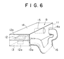
loudspeaker unit 2,acoustic pipe 4, andair chamber 5 as described above, the dimension t1 of theloudspeaker enclosure 1 can be made small. - Figs. 6 to 8 show the fifth embodiment, wherein Fig. 6 is a perspective view, Fig. 7 is a sectional view, and Fig. 8 is a front view.
- In Figs. 6 to 8, reference numeral 11 represents a loudspeaker enclosure, and 12 a loudspeaker unit. The
loudspeaker unit 12 is mounted between asmall air chamber 13 and anair chamber 14 such that sounds radiated to the back side 12a of theloudspeaker unit 12 are introduced into thesmall air chamber 13 and sounds radiated to the front side 13b of theloudspeaker unit 12 are introduced into theair chamber 14. - A
port 15 is mounted within theair chamber 14. Between anaperture 13a formed in the wall of thesmall air chamber 13 and anaperture 14a formed in the wall of theair chamber 14, there is connected a flexibleacoustic pipe 16. - The resonance frequency of the
port 15 is set at substantially the same frequency where the half wavelength stands in theacoustic pipe 16. - In the low sound loudspeaker system constructed as above, a bass reflex type loudspeaker system B constructed of the
air chamber 14 and theport 15 is provided at thefront side 12b of theloudspeaker unit 12. Therefore, sounds radiated from thefront side 12b of theloudspeaker unit 12 and introduced into theair chamber 14 are outputted to the outside 17 of the loudspeaker enclosure 11, having low sound components of approximately the opposite phase and near at the resonance frequency of theport 15. - In the meantime, sounds radiated from the back side 12a of the
loudspeaker unit 12 and guided via theacoustic pipe 16 to theair chamber 14 have low sound components, near at theaperture 14a, of approximately the opposite phase to the phase at the back side 12a and of approximately the same frequency where the half wavelength stands in theacoustic pipe 16 of the low sound loudspeaker system. - Sounds passed through the
acoustic pipe 16 are also introduced in the bass reflex type loudspeaker system B. In this bass reflex type loudspeaker system B, sounds from thefront side 12b of theloudspeaker unit 12 and those from the back side 12a are added together, reproducing low sound components more efficiently. - Reproduction efficiency is improved considerably because of the structure that the resonance frequency of the
port 15 is set at substantially the same frequency where the half wavelength stands in theacoustic pipe 16. - In the fifth embodiment, with the structural arrangement of the
loudspeaker unit 12,acoustic pipe 16, andair chamber 14 as described above, the dimension t2 of theloudspeaker enclosure 1 can be made small. - A plurality of
apertures 13a and 14b may be formed to thereby further improve the freedom of installation. In this case, it is needless to say that non-use apertures should be closed. - If the length of the
acoustic pipe 16 is made variable, the sound quality can be adjusted, allowing various customized applications. - According to the low sound speaker system shown in Figs. 5 to 8, the above structural arrangement makes the enclosure compact. Therefore, the system can be easily installed below a vehicle seat.
- Since the acoustic pipe is mounted outside of the enclosure, it may be made smaller. Furthermore, since the acoustic pipe is flexible, the degree of freedom can be further improved in installing the system within a small space of a vehicle.
- Provision of a bass reflex type loudspeaker system composed of the air chamber and port enables efficient radiation of low sound components to the outside of the enclosure.
- Furthermore, the system of this invention is simple in structure and cost effective, allowing easy installation.
Claims (9)
1. A low sound loudspeaker system comprising:
an acoustic pipe extending from the back side of a loudspeaker unit;
an air chamber provided at the front side of said loudspeaker unit; and
a bass reflex port provided within said air chamber;
said acoustic pipe communicating with said air chamber via an aperture of said acous-
tic pipe.
2. A low sound loudspeaker system according to claim 1, wherein the resonance frequency of said bass reflex port is set at substantially the same frequency where the half wavelength stands in said acoustic pipe.
3. A low sound loudspeaker system according to claim 1, wherein a partition plate for defining said air chamber and said acoustic pipe is provided, and the said partition plate forms an inner and upper surface of said acoustic pipe at the area from one end to the other end of said acoustic pipe.
4. A low sound loudspeaker system according to claim 3, wherein the resonance frequency of said bass reflex port is set at substantially the same frequency where the half wavelength stands in said acoustic pipe.
5. A low sound loudspeaker system according to claim 3, wherein the direction of radiating sounds from said loudspeaker unit differs approximately 90 degrees from the direction of said bass reflex port.
6. A low sound loudspeaker system according to claim 5, wherein the resonance frequency of said bass reflex port is set a substantially the same frequency where the half wavelength stands in said acoustic pipe.
7. A low sound loudspeaker system according to claim 1, wherein said acoustic pipe is mounted at the outside of the enclosure of said system, and is made flexible.
8. A low sound loudspeaker system according to claim 7, wherein the direction of radiating sounds from said loudspeaker unit differs approximately 90 degrees from the direction of said bass reflex port.
9. A low sound loudspeaker system according to claim 7, wherein the resonance frequency of said bass reflex port is set at substantially the same frequency where the half wavelength stands in said acoustic pipe.
Priority Applications (1)
| Application Number | Priority Date | Filing Date | Title |
|---|---|---|---|
| EP90119419A EP0480087A1 (en) | 1990-10-10 | 1990-10-10 | Low frequency loudspeaker system |
Applications Claiming Priority (1)
| Application Number | Priority Date | Filing Date | Title |
|---|---|---|---|
| EP90119419A EP0480087A1 (en) | 1990-10-10 | 1990-10-10 | Low frequency loudspeaker system |
Publications (1)
| Publication Number | Publication Date |
|---|---|
| EP0480087A1 true EP0480087A1 (en) | 1992-04-15 |
Family
ID=8204599
Family Applications (1)
| Application Number | Title | Priority Date | Filing Date |
|---|---|---|---|
| EP90119419A Withdrawn EP0480087A1 (en) | 1990-10-10 | 1990-10-10 | Low frequency loudspeaker system |
Country Status (1)
| Country | Link |
|---|---|
| EP (1) | EP0480087A1 (en) |
Cited By (4)
| Publication number | Priority date | Publication date | Assignee | Title |
|---|---|---|---|---|
| GB2256343A (en) * | 1991-05-29 | 1992-12-02 | Hughes Aircraft Co | High efficiency low frequency speaker system |
| WO1997008916A1 (en) * | 1995-08-25 | 1997-03-06 | Britannia Investment Corporation | Improved bass-reflex loudspeaker |
| CN1062681C (en) * | 1994-05-09 | 2001-02-28 | 株式会社日立制作所 | Display device |
| GB2408676A (en) * | 2003-12-05 | 2005-06-08 | Peter Roots | Loudspeaker stand with resonating tube |
Citations (3)
| Publication number | Priority date | Publication date | Assignee | Title |
|---|---|---|---|---|
| US2224919A (en) * | 1937-03-31 | 1940-12-17 | Rca Corp | Loud-speaker |
| DE3214226A1 (en) * | 1982-04-17 | 1983-10-20 | Standard Elektrik Lorenz Ag, 7000 Stuttgart | Loudspeaker with indirect routing of the sound |
| US4875546A (en) * | 1988-06-02 | 1989-10-24 | Teledyne Industries, Inc. | Loudspeaker with acoustic band-pass filter |
-
1990
- 1990-10-10 EP EP90119419A patent/EP0480087A1/en not_active Withdrawn
Patent Citations (3)
| Publication number | Priority date | Publication date | Assignee | Title |
|---|---|---|---|---|
| US2224919A (en) * | 1937-03-31 | 1940-12-17 | Rca Corp | Loud-speaker |
| DE3214226A1 (en) * | 1982-04-17 | 1983-10-20 | Standard Elektrik Lorenz Ag, 7000 Stuttgart | Loudspeaker with indirect routing of the sound |
| US4875546A (en) * | 1988-06-02 | 1989-10-24 | Teledyne Industries, Inc. | Loudspeaker with acoustic band-pass filter |
Non-Patent Citations (1)
| Title |
|---|
| PATENT ABSTRACTS OF JAPAN, vol. 8, no. 39 (E-228)[1476], 21st February 1984; & JP-A-58 196 797 (MATSUSHITA K.K.) 16-11-1983 * |
Cited By (6)
| Publication number | Priority date | Publication date | Assignee | Title |
|---|---|---|---|---|
| GB2256343A (en) * | 1991-05-29 | 1992-12-02 | Hughes Aircraft Co | High efficiency low frequency speaker system |
| CN1062681C (en) * | 1994-05-09 | 2001-02-28 | 株式会社日立制作所 | Display device |
| WO1997008916A1 (en) * | 1995-08-25 | 1997-03-06 | Britannia Investment Corporation | Improved bass-reflex loudspeaker |
| US5696357A (en) * | 1995-08-25 | 1997-12-09 | Polk Investment Corporation | Bass-reflex loudspeaker |
| GB2408676A (en) * | 2003-12-05 | 2005-06-08 | Peter Roots | Loudspeaker stand with resonating tube |
| GB2408676B (en) * | 2003-12-05 | 2009-01-07 | Peter Roots | Hifi speaker stand |
Similar Documents
| Publication | Publication Date | Title |
|---|---|---|
| US5197103A (en) | Low sound loudspeaker system | |
| US5471019A (en) | Multiple chamber loudspeaker system | |
| KR101217411B1 (en) | Bass reflex type loudspeaker apparatus, loudspeaker box and image display apparatus | |
| US4942939A (en) | Speaker system with folded audio transmission passage | |
| US5097513A (en) | Speaker system enclosure integrated with amplifier circuit board | |
| US3356179A (en) | High fidelity speaker enclosure | |
| US7207413B2 (en) | Closed loop embedded audio transmission line technology for loudspeaker enclosures and systems | |
| EP0453230B1 (en) | Speaker system | |
| US5335283A (en) | Loudspeaker apparatus for electronic keyboard musical instrument | |
| US4817168A (en) | Directional microphone | |
| JP3611854B2 (en) | Speaker system | |
| US5296656A (en) | Sound collecting and concentrating device for attaching to the back of multiple loudspeakers | |
| US4452333A (en) | Speaker system | |
| EP1452066B1 (en) | Bass-reflex loudspeaker system and method of manufacturing the same | |
| EP0480087A1 (en) | Low frequency loudspeaker system | |
| EP1736029A1 (en) | Distributed acoustic cabinet | |
| GB2056815A (en) | Coaxial multi-way planar diaphragm loudspeaker system | |
| JPH03108999A (en) | Speaker system | |
| JPH0633749Y2 (en) | Speaker system for bass reproduction | |
| JP3473279B2 (en) | Speaker device | |
| JPH0787628B2 (en) | Speaker system for bass reproduction | |
| JP2579365Y2 (en) | Structure of speaker system for bass | |
| JP2784063B2 (en) | Bass stereo playback device | |
| JPH0470199A (en) | Phase inverting type speaker system | |
| CN112929770A (en) | Sound cavity structure and sound box |
Legal Events
| Date | Code | Title | Description |
|---|---|---|---|
| PUAI | Public reference made under article 153(3) epc to a published international application that has entered the european phase |
Free format text: ORIGINAL CODE: 0009012 |
|
| AK | Designated contracting states |
Kind code of ref document: A1 Designated state(s): DE FR GB |
|
| 17P | Request for examination filed |
Effective date: 19921016 |
|
| RAP1 | Party data changed (applicant data changed or rights of an application transferred) |
Owner name: KABUSHIKI KAISHA KENWOOD |
|
| 17Q | First examination report despatched |
Effective date: 19940413 |
|
| STAA | Information on the status of an ep patent application or granted ep patent |
Free format text: STATUS: THE APPLICATION HAS BEEN WITHDRAWN |
|
| RAP3 | Party data changed (applicant data changed or rights of an application transferred) |
Owner name: KABUSHIKI KAISHA KENWOOD |
|
| 18W | Application withdrawn |
Withdrawal date: 19940811 |