EP0479558A2 - Mold arm closing mechanism for an individual section machine - Google Patents
Mold arm closing mechanism for an individual section machine Download PDFInfo
- Publication number
- EP0479558A2 EP0479558A2 EP91308992A EP91308992A EP0479558A2 EP 0479558 A2 EP0479558 A2 EP 0479558A2 EP 91308992 A EP91308992 A EP 91308992A EP 91308992 A EP91308992 A EP 91308992A EP 0479558 A2 EP0479558 A2 EP 0479558A2
- Authority
- EP
- European Patent Office
- Prior art keywords
- mold support
- mold
- lever arm
- pin
- axis
- Prior art date
- Legal status (The legal status is an assumption and is not a legal conclusion. Google has not performed a legal analysis and makes no representation as to the accuracy of the status listed.)
- Granted
Links
Images


Classifications
-
- C—CHEMISTRY; METALLURGY
- C03—GLASS; MINERAL OR SLAG WOOL
- C03B—MANUFACTURE, SHAPING, OR SUPPLEMENTARY PROCESSES
- C03B9/00—Blowing glass; Production of hollow glass articles
- C03B9/30—Details of blowing glass; Use of materials for the moulds
- C03B9/34—Glass-blowing moulds not otherwise provided for
- C03B9/353—Mould holders ; Mould opening and closing mechanisms
- C03B9/3532—Mechanisms for holders of half moulds moving by rotation about a common vertical axis
- C03B9/3535—Mechanisms for holders of half moulds moving by rotation about a common vertical axis with the half moulds parallel upon opening and closing
Definitions
- the present invention relates to glass forming machines generally referred to as individual section machines and more specifically to the mechanism for closing opposed mold arms in such machines.
- Glass bottles are conventionally made in an individual section machine which is made up of a number of individual sections each having a blank side and a blow side. Opposed mold halves are supported on pivotally closeable mold arms which are closed during the formation of the parison in the blank mold or the formation of the bottle in the blow mold.
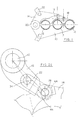
- the mold holding apparatus includes a lower mold support 10for receiving three mold halves 12, an upper support arm 14, which pivotally supports a first mold support 16, receiving the inner most mold half and a second mold support 18, which receives the two outermost mold halves and which is pivotally supported on the free end of the first mold support 16.
- the lower mold support 10 and the upper mold support 14 are pivotally secured to a post 20.
- a link 22 controls the pivotal displacement of each mold support.
- mold support pin 36 is smaller than the associated link hole 37 and the axis of both the support pin 36 and link hole 37 are designed to be the same distance from the axis of lever pin 34 when the molds are closed. This prevents any force from being transmitted from the support pin 36 to the link 22. At this position the cam will resist opening movement so that line air used to displace the linkage to this closed position can be turned off. This will permit quicker application of line pressure, at the conclusion of bottle or parison formation to open the linkage.
- the right hand end of this link hole 37 engages the support pin 36 to pull the mold support open.
- the left hand end of the link hole engages the support pin 36 to push the mold support to the closed position.
- FIGS. 4A, 4B and 4C An alternate cam design is illustrated in figures 4A, 4B and 4C.
- the axis of the drive shaft 30, lever pin 34, and mold support pin 37 are all in the same plane at the fully closed position with the line of force from the roller follower 44 to the cam 42 also intersecting the axis of the drive shaft 30.
- the mold support pin 36 is forced by the increasing radius of the cam surface, against a side of the enlarged hole to prevent further rotative displacement of the lever arm.
Abstract
Description
- The present invention relates to glass forming machines generally referred to as individual section machines and more specifically to the mechanism for closing opposed mold arms in such machines.
- Glass bottles are conventionally made in an individual section machine which is made up of a number of individual sections each having a blank side and a blow side. Opposed mold halves are supported on pivotally closeable mold arms which are closed during the formation of the parison in the blank mold or the formation of the bottle in the blow mold.
- During these processes large forces are generated which tend to open the molds spreading these arms apart. Conventionally, this is inhibited by increasing the mold closing forces and this requires stronger and stronger parts capable of responding to these increased forces.
- It is accordingly an object of the present invention to provide a very simple mechanism for inhibiting the opening of the closed mold arms during parison or bottle formation.
- Other objects and advantages of the present invention will become apparent from the following portion of the specification and from the accompanying drawings, which illustrate, in accordance with the mandate of the patent statutes, a presently preferred embodiment of the invention.
- Referring to the Drawings:
- Figure 1 is a top view of one of the opposed pair of mold closing arms made in accordance with the teachings of the present invention;
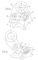
- Figures 2A, 2B, and 2C are views similar to figure 1 showing a portion of the mold closing arm as it is displaced to a fully closed position;
- Figure 3 is a top view showing the support structure for the drive shaft for these mechanisms; and
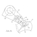
- Figures 4A, 4B, and 4C are views similar to figures 2A, 2B and 2C showing the same portion of the mold closing arm having a modified cam as it is displaced through its last portion of displacement to a fully closed positions; and
- The mold holding apparatus includes a lower mold support 10for receiving three
mold halves 12, anupper support arm 14, which pivotally supports afirst mold support 16, receiving the inner most mold half and asecond mold support 18, which receives the two outermost mold halves and which is pivotally supported on the free end of thefirst mold support 16. Thelower mold support 10 and theupper mold support 14 are pivotally secured to apost 20. Alink 22 controls the pivotal displacement of each mold support. - Referring to figure 2A, counterclockwise rotation of a
drive shaft 30 conjointly rotates anintegral lever arm 32. This forces thelink 22 which is secured to alever pin 34 at one end and which is associated with amold support pin 36 at the other end to move horizontally to the right, thereby rotating the mold support aboutshaft 20 to close the molds. - When the
lever arm 32 rotates to the position shown in figure 2B, thesurface 40 of acam 42 which is secured to thelever arm 32 engages a roller fol-iower 44 which is rotatably supported on themold support pin 36. Continued closing movement causes the roller follower to ride along thecam surface 42 until the follower settles into acylindrical portion 46 of the cam surface 42 (Figure 2C). At this "mold closed" position, which corresponds to the mold closing assembly shown in Fig, 1, the line of force from theroller follower 44 to thecam 42 intersects the axis of thedrive shaft 30. This is achieved by mechanically separatingmold support pin 36 and the connectinglink 22 at this time. As can be seen from figure 2B,mold support pin 36 is smaller than the associatedlink hole 37 and the axis of both thesupport pin 36 andlink hole 37 are designed to be the same distance from the axis oflever pin 34 when the molds are closed. This prevents any force from being transmitted from thesupport pin 36 to thelink 22. At this position the cam will resist opening movement so that line air used to displace the linkage to this closed position can be turned off. This will permit quicker application of line pressure, at the conclusion of bottle or parison formation to open the linkage. When the mold supports are displaced to the open position, the right hand end of thislink hole 37 engages thesupport pin 36 to pull the mold support open. The left hand end of the link hole engages thesupport pin 36 to push the mold support to the closed position. - Since there is in effect, a continuous metal block behind the mold support, any movement of the mold support pin will result only from the deflection of the drive shaft and this will be minimized by supporting the drive shafts, in the region of the lever arm with an anti-deflection bracket 50 (Figure 4).
- An alternate cam design is illustrated in figures 4A, 4B and 4C. In this design the axis of the
drive shaft 30,lever pin 34, andmold support pin 37, are all in the same plane at the fully closed position with the line of force from theroller follower 44 to thecam 42 also intersecting the axis of thedrive shaft 30. In this design however, themold support pin 36 is forced by the increasing radius of the cam surface, against a side of the enlarged hole to prevent further rotative displacement of the lever arm.
Claims (1)
Applications Claiming Priority (2)
| Application Number | Priority Date | Filing Date | Title |
|---|---|---|---|
| US591427 | 1990-10-01 | ||
| US07/591,427 US5019147A (en) | 1990-10-01 | 1990-10-01 | Mold arm closing mechanism for an individual section machine |
Publications (3)
| Publication Number | Publication Date |
|---|---|
| EP0479558A2 true EP0479558A2 (en) | 1992-04-08 |
| EP0479558A3 EP0479558A3 (en) | 1993-09-22 |
| EP0479558B1 EP0479558B1 (en) | 1997-01-29 |
Family
ID=24366444
Family Applications (1)
| Application Number | Title | Priority Date | Filing Date |
|---|---|---|---|
| EP91308992A Expired - Lifetime EP0479558B1 (en) | 1990-10-01 | 1991-10-01 | Mold arm closing mechanism for an individual section machine |
Country Status (4)
| Country | Link |
|---|---|
| US (1) | US5019147A (en) |
| EP (1) | EP0479558B1 (en) |
| JP (1) | JPH04243919A (en) |
| DE (1) | DE69124447T2 (en) |
Families Citing this family (15)
| Publication number | Priority date | Publication date | Assignee | Title |
|---|---|---|---|---|
| US5476743A (en) * | 1994-12-16 | 1995-12-19 | Xerox Corporation | Liquid developer compositions with organic additives |
| FR2766171B1 (en) * | 1997-07-15 | 1999-08-20 | Saint Gobain Emballage | PIVOTING DRAWER MOLD |
| US5938809A (en) * | 1997-11-06 | 1999-08-17 | Emhart Glass Sa | I.S. machine |
| FR2771083B1 (en) * | 1997-11-06 | 2000-05-26 | Emhart Glass Sa | MOLD OPENING AND CLOSING MECHANISM FOR INDIVIDUAL SECTION FORMING MACHINE |
| FR2770507B1 (en) * | 1997-11-06 | 2000-07-28 | Emhart Glass Sa | INDIVIDUAL SECTOR TRAINING MACHINE |
| US5824131A (en) * | 1997-11-06 | 1998-10-20 | Emhart Glass Machinery Investments Inc. | Mold opening and closing mechanism for an I.S. machine |
| FR2770511B1 (en) * | 1997-11-06 | 2000-05-12 | Emhart Glass Sa | MOLD OPENING AND CLOSING MECHANISM FOR AN INDIVIDUAL SECTOR FORMING MACHINE |
| US5830254A (en) * | 1997-11-06 | 1998-11-03 | Emhart Glass Machinery Investments Inc. | Mold opening and closing mechanism for an I.S. machine |
| US5876476A (en) * | 1997-11-06 | 1999-03-02 | Emhart Glass S.A. | I.S. machine |
| FR2770510B1 (en) * | 1997-11-06 | 2000-03-31 | Emhart Glass Sa | MOLD OPENING AND CLOSING MECHANISM FOR AN INDIVIDUAL SECTOR FORMING MACHINE |
| US5803945A (en) * | 1997-11-06 | 1998-09-08 | Emhart Glass Machinery Investments Inc. | Mold opening and closing mechanism for an I.S. machine |
| DE29916216U1 (en) | 1999-09-15 | 2000-02-10 | Heye Hermann Fa | Device for driving two mold half holders of a glass molding machine |
| US20030101767A1 (en) * | 2001-12-05 | 2003-06-05 | Hyre Matthew R. | Glass container forming machine |
| US7845193B2 (en) | 2007-05-16 | 2010-12-07 | Owens-Backway Glass Container Inc | Apparatus for opening and closing molds in a glassware forming machine |
| US8047022B2 (en) | 2007-05-16 | 2011-11-01 | Owens-Brockway Glass Container Inc. | Apparatus for opening and closing molds in a glassware forming machine |
Citations (6)
| Publication number | Priority date | Publication date | Assignee | Title |
|---|---|---|---|---|
| GB506499A (en) * | 1937-08-27 | 1939-05-30 | Henry Cotton Daubenspeck | Improvements in glass bottle making machines |
| US2307563A (en) * | 1939-08-16 | 1943-01-05 | Lynch Corp | Glass mold operating mechanism |
| US2748536A (en) * | 1954-09-24 | 1956-06-05 | Owens Illinois Glass Co | Mold closing mechanism |
| US4375979A (en) * | 1981-11-19 | 1983-03-08 | Maul Technology Corporation | Glass forming apparatus |
| GB2140407A (en) * | 1983-05-26 | 1984-11-28 | Owens Illinois Inc | Quadruple cavity glass mold operating apparatus |
| EP0195599A1 (en) * | 1985-03-19 | 1986-09-24 | Emhart Industries, Inc. | Mould opening and closing mechanism for a glassware forming machine |
Family Cites Families (1)
| Publication number | Priority date | Publication date | Assignee | Title |
|---|---|---|---|---|
| US3798019A (en) * | 1972-05-22 | 1974-03-19 | Emhart Corp | Mold holder arm and insert opening mechanism |
-
1990
- 1990-10-01 US US07/591,427 patent/US5019147A/en not_active Expired - Lifetime
-
1991
- 1991-10-01 DE DE69124447T patent/DE69124447T2/en not_active Expired - Lifetime
- 1991-10-01 EP EP91308992A patent/EP0479558B1/en not_active Expired - Lifetime
- 1991-10-01 JP JP3253777A patent/JPH04243919A/en active Pending
Patent Citations (6)
| Publication number | Priority date | Publication date | Assignee | Title |
|---|---|---|---|---|
| GB506499A (en) * | 1937-08-27 | 1939-05-30 | Henry Cotton Daubenspeck | Improvements in glass bottle making machines |
| US2307563A (en) * | 1939-08-16 | 1943-01-05 | Lynch Corp | Glass mold operating mechanism |
| US2748536A (en) * | 1954-09-24 | 1956-06-05 | Owens Illinois Glass Co | Mold closing mechanism |
| US4375979A (en) * | 1981-11-19 | 1983-03-08 | Maul Technology Corporation | Glass forming apparatus |
| GB2140407A (en) * | 1983-05-26 | 1984-11-28 | Owens Illinois Inc | Quadruple cavity glass mold operating apparatus |
| EP0195599A1 (en) * | 1985-03-19 | 1986-09-24 | Emhart Industries, Inc. | Mould opening and closing mechanism for a glassware forming machine |
Also Published As
| Publication number | Publication date |
|---|---|
| US5019147A (en) | 1991-05-28 |
| DE69124447D1 (en) | 1997-03-13 |
| EP0479558A3 (en) | 1993-09-22 |
| EP0479558B1 (en) | 1997-01-29 |
| DE69124447T2 (en) | 1997-05-15 |
| JPH04243919A (en) | 1992-09-01 |
Similar Documents
| Publication | Publication Date | Title |
|---|---|---|
| US5019147A (en) | Mold arm closing mechanism for an individual section machine | |
| US20090220630A1 (en) | Method of controlling the opening and closing of a blow mold and blowing device for implementing same | |
| US6079541A (en) | Container gripper, in particular for bottles | |
| US20060093699A1 (en) | Device for blow-molding or stretch blow molding of thermoplastic materials containers | |
| MX2007009536A (en) | Rotary device for transferring containers. | |
| CN110546111B (en) | Takeout mechanism of machine for forming glass articles | |
| KR20010040743A (en) | Transfer device for hollow body comprising a neck | |
| US4486215A (en) | Quadruple cavity glass mold operating apparatus | |
| EP1445090A1 (en) | Variable-pitch arm star construction for rotary blow molding machines | |
| EP0345933A1 (en) | Glassware forming machine | |
| US3463484A (en) | Sheet gripping control mechanism for printing machines | |
| US3994403A (en) | Gripping devices for multi-stage upsetting presses | |
| CN218160139U (en) | Electric appliance cabinet with linkage auxiliary grounding switch | |
| US5271757A (en) | Glassware takeout mechanism with parallel linkage | |
| US4375979A (en) | Glass forming apparatus | |
| US4566894A (en) | Deflector adjustment for a glassware forming machine | |
| JPH11502601A (en) | Tilt adapter for support arm mechanism | |
| DE10054913A1 (en) | IS glass forming machine | |
| CN110406076B (en) | Connecting rod type linkage mechanism for bottle blowing machine die carrier | |
| EP2145861A1 (en) | Molds opening/closing group of a forming glass machine items | |
| US4412778A (en) | Tong arm assembly | |
| US20080184742A1 (en) | Baffle system for blank molds of a glassware forming machine | |
| JP3245131B2 (en) | Mold opening and closing device for bottle making machine | |
| EP0212367A2 (en) | Spring-mounted gripper for sheet-fed rotary printing machines | |
| JP3025388B2 (en) | Gaming machine |
Legal Events
| Date | Code | Title | Description |
|---|---|---|---|
| PUAI | Public reference made under article 153(3) epc to a published international application that has entered the european phase |
Free format text: ORIGINAL CODE: 0009012 |
|
| AK | Designated contracting states |
Kind code of ref document: A2 Designated state(s): DE FR GB IT |
|
| PUAL | Search report despatched |
Free format text: ORIGINAL CODE: 0009013 |
|
| AK | Designated contracting states |
Kind code of ref document: A3 Designated state(s): DE FR GB IT |
|
| 17P | Request for examination filed |
Effective date: 19940307 |
|
| 17Q | First examination report despatched |
Effective date: 19950810 |
|
| GRAG | Despatch of communication of intention to grant |
Free format text: ORIGINAL CODE: EPIDOS AGRA |
|
| GRAH | Despatch of communication of intention to grant a patent |
Free format text: ORIGINAL CODE: EPIDOS IGRA |
|
| GRAH | Despatch of communication of intention to grant a patent |
Free format text: ORIGINAL CODE: EPIDOS IGRA |
|
| GRAA | (expected) grant |
Free format text: ORIGINAL CODE: 0009210 |
|
| AK | Designated contracting states |
Kind code of ref document: B1 Designated state(s): DE FR GB IT |
|
| REF | Corresponds to: |
Ref document number: 69124447 Country of ref document: DE Date of ref document: 19970313 |
|
| ET | Fr: translation filed | ||
| ITF | It: translation for a ep patent filed |
Owner name: 0508;80MIFUFFICIO BREVETTI RICCARDI & C. |
|
| PLBE | No opposition filed within time limit |
Free format text: ORIGINAL CODE: 0009261 |
|
| STAA | Information on the status of an ep patent application or granted ep patent |
Free format text: STATUS: NO OPPOSITION FILED WITHIN TIME LIMIT |
|
| 26N | No opposition filed | ||
| REG | Reference to a national code |
Ref country code: FR Ref legal event code: TP |
|
| REG | Reference to a national code |
Ref country code: GB Ref legal event code: IF02 |
|
| PGFP | Annual fee paid to national office [announced via postgrant information from national office to epo] |
Ref country code: FR Payment date: 20101105 Year of fee payment: 20 |
|
| PGFP | Annual fee paid to national office [announced via postgrant information from national office to epo] |
Ref country code: DE Payment date: 20101027 Year of fee payment: 20 |
|
| PGFP | Annual fee paid to national office [announced via postgrant information from national office to epo] |
Ref country code: GB Payment date: 20101025 Year of fee payment: 20 Ref country code: IT Payment date: 20101027 Year of fee payment: 20 |
|
| REG | Reference to a national code |
Ref country code: DE Ref legal event code: R071 Ref document number: 69124447 Country of ref document: DE |
|
| REG | Reference to a national code |
Ref country code: DE Ref legal event code: R071 Ref document number: 69124447 Country of ref document: DE |
|
| REG | Reference to a national code |
Ref country code: GB Ref legal event code: PE20 Expiry date: 20110930 |
|
| PG25 | Lapsed in a contracting state [announced via postgrant information from national office to epo] |
Ref country code: GB Free format text: LAPSE BECAUSE OF EXPIRATION OF PROTECTION Effective date: 20110930 |
|
| PG25 | Lapsed in a contracting state [announced via postgrant information from national office to epo] |
Ref country code: DE Free format text: LAPSE BECAUSE OF EXPIRATION OF PROTECTION Effective date: 20111002 |