EP0479514A1 - Magnetic field generating device used for MRI - Google Patents
Magnetic field generating device used for MRI Download PDFInfo
- Publication number
- EP0479514A1 EP0479514A1 EP19910308901 EP91308901A EP0479514A1 EP 0479514 A1 EP0479514 A1 EP 0479514A1 EP 19910308901 EP19910308901 EP 19910308901 EP 91308901 A EP91308901 A EP 91308901A EP 0479514 A1 EP0479514 A1 EP 0479514A1
- Authority
- EP
- European Patent Office
- Prior art keywords
- magnetic pole
- magnetic field
- mri
- magnetic
- generating device
- Prior art date
- Legal status (The legal status is an assumption and is not a legal conclusion. Google has not performed a legal analysis and makes no representation as to the accuracy of the status listed.)
- Granted
Links
- 229910000976 Electrical steel Inorganic materials 0.000 claims abstract description 66
- 238000010030 laminating Methods 0.000 claims abstract description 43
- 239000000696 magnetic material Substances 0.000 claims description 47
- 230000005389 magnetism Effects 0.000 abstract description 20
- XEEYBQQBJWHFJM-UHFFFAOYSA-N Iron Chemical compound [Fe] XEEYBQQBJWHFJM-UHFFFAOYSA-N 0.000 description 43
- 238000002595 magnetic resonance imaging Methods 0.000 description 27
- 229910052742 iron Inorganic materials 0.000 description 22
- 230000000694 effects Effects 0.000 description 16
- 239000000463 material Substances 0.000 description 11
- 229910000831 Steel Inorganic materials 0.000 description 8
- 239000010959 steel Substances 0.000 description 8
- 230000000052 comparative effect Effects 0.000 description 5
- 230000004907 flux Effects 0.000 description 5
- 238000003475 lamination Methods 0.000 description 5
- 229920003002 synthetic resin Polymers 0.000 description 5
- 239000000057 synthetic resin Substances 0.000 description 5
- 238000005096 rolling process Methods 0.000 description 4
- 239000000853 adhesive Substances 0.000 description 3
- 230000001070 adhesive effect Effects 0.000 description 3
- 229910001209 Low-carbon steel Inorganic materials 0.000 description 2
- 239000002390 adhesive tape Substances 0.000 description 2
- 239000012141 concentrate Substances 0.000 description 2
- 230000002542 deteriorative effect Effects 0.000 description 2
- 238000009413 insulation Methods 0.000 description 2
- 230000010354 integration Effects 0.000 description 2
- 238000005259 measurement Methods 0.000 description 2
- 229910052761 rare earth metal Inorganic materials 0.000 description 2
- 229920005989 resin Polymers 0.000 description 2
- 239000011347 resin Substances 0.000 description 2
- 239000000758 substrate Substances 0.000 description 2
- 241001137251 Corvidae Species 0.000 description 1
- 229910052779 Neodymium Inorganic materials 0.000 description 1
- 229910052777 Praseodymium Inorganic materials 0.000 description 1
- XUIMIQQOPSSXEZ-UHFFFAOYSA-N Silicon Chemical compound [Si] XUIMIQQOPSSXEZ-UHFFFAOYSA-N 0.000 description 1
- 229910000828 alnico Inorganic materials 0.000 description 1
- 230000015572 biosynthetic process Effects 0.000 description 1
- 239000013590 bulk material Substances 0.000 description 1
- 239000010941 cobalt Substances 0.000 description 1
- 229910017052 cobalt Inorganic materials 0.000 description 1
- GUTLYIVDDKVIGB-UHFFFAOYSA-N cobalt atom Chemical compound [Co] GUTLYIVDDKVIGB-UHFFFAOYSA-N 0.000 description 1
- 238000010276 construction Methods 0.000 description 1
- 238000005520 cutting process Methods 0.000 description 1
- 238000009826 distribution Methods 0.000 description 1
- 239000003822 epoxy resin Substances 0.000 description 1
- 238000005470 impregnation Methods 0.000 description 1
- 239000006247 magnetic powder Substances 0.000 description 1
- 230000005415 magnetization Effects 0.000 description 1
- 239000002075 main ingredient Substances 0.000 description 1
- 238000004519 manufacturing process Methods 0.000 description 1
- 229910000889 permalloy Inorganic materials 0.000 description 1
- 235000015108 pies Nutrition 0.000 description 1
- 229920000647 polyepoxide Polymers 0.000 description 1
- 239000004814 polyurethane Substances 0.000 description 1
- 229920002635 polyurethane Polymers 0.000 description 1
- 150000002910 rare earth metals Chemical class 0.000 description 1
- 230000000630 rising effect Effects 0.000 description 1
- 229920006395 saturated elastomer Polymers 0.000 description 1
- 238000007790 scraping Methods 0.000 description 1
- 230000035945 sensitivity Effects 0.000 description 1
- 229910052710 silicon Inorganic materials 0.000 description 1
- 239000010703 silicon Substances 0.000 description 1
- 230000003068 static effect Effects 0.000 description 1
- 239000010409 thin film Substances 0.000 description 1
- 229910000859 α-Fe Inorganic materials 0.000 description 1
Images


Classifications
-
- H—ELECTRICITY
- H01—ELECTRIC ELEMENTS
- H01F—MAGNETS; INDUCTANCES; TRANSFORMERS; SELECTION OF MATERIALS FOR THEIR MAGNETIC PROPERTIES
- H01F7/00—Magnets
- H01F7/02—Permanent magnets [PM]
- H01F7/0273—Magnetic circuits with PM for magnetic field generation
- H01F7/0278—Magnetic circuits with PM for magnetic field generation for generating uniform fields, focusing, deflecting electrically charged particles
-
- G—PHYSICS
- G01—MEASURING; TESTING
- G01R—MEASURING ELECTRIC VARIABLES; MEASURING MAGNETIC VARIABLES
- G01R33/00—Arrangements or instruments for measuring magnetic variables
- G01R33/20—Arrangements or instruments for measuring magnetic variables involving magnetic resonance
- G01R33/28—Details of apparatus provided for in groups G01R33/44 - G01R33/64
- G01R33/38—Systems for generation, homogenisation or stabilisation of the main or gradient magnetic field
- G01R33/383—Systems for generation, homogenisation or stabilisation of the main or gradient magnetic field using permanent magnets
Definitions
- the present invention concerns an improvement for a magnetic field generating device used, for example, in a magnetic resonance imaging apparatus (hereinafter referred to as MRI) for medical, in particular, use and it relates to a magnetic field generating device used for MRI, in which a pair of magnetic poles constituted by laminating and integrating a plurality of non-oriented silicon steel sheets are opposed to each other with a gap defined therebetween, for reducing the eddy current and the phenomenon of residual magnetism in the magnetic poles caused by gradient magnetic field coils, without deteriorating the uniformity of the magnetic field in the gap.
- MRI magnetic resonance imaging apparatus
- MRI is an apparatus adapted to partially or wholly locating a person to be diagnosed in a gap of a magnetic field generating device that generates an intense magnetic field, for obtaining a tomographic image of an object and capable of showing as far as the property of the tissue thereof.
- the gap has such a space as capable of partially or wholly locating the person to be diagnosed and it is also required to form a stable intense magnetic field usually of 0.02 to 2.0 T and at an accuracy of less than 1 x 10- 4 in an image pick-up view field in the gap, in order to obtain a clear tomographic image.
- a known magnetic field generating device used for MRI has a constitution as shown in Fig. 12(a), (b) in which a pair of components 1, 1 made of permanent magnets are opposed to each other as a magnetic field generating source, with one end of each of them being secured with a magnetic pole 2 and the other ends of them are connected by means of yokes 3, to generate a static magnetic field in a gap 4 defined between the magnetic poles 2 and 2.
- An annular protrusion 5 is disposed at the periphery of each of the magnetic poles 2, 2 in order to improve the uniformity of the magnetic field distribution in the gap 4, and it is usually made of a plate-shaped bulk (one piece product) prepared by scraping from magnetic material such as electromagnetic soft iron or pure iron (refer to Japanese Patent Laid Open Sho 60-88407).
- Gladient magnetic field coils 6 disposed in the vicinity of each of the magnetic poles 2, 2 usually comprise three sets of coil groups corresponding to three directions X, Y and Z for obtaining positional information in the gap 4, but they are described simply in the drawing.
- a gradient magnetic field changing with time in a trapezoidal waveform can be generated in a desired direction.
- the eddy current forms a magnetic field in the direction opposite to the magnetic field formed with the gradient magnetic field coils 6, it takes a long time for the gradient magnetic field to reach a predetermined intensity.
- a magnetic field generating device using, as the magnetic pole, a plate-shaped lamination comprising soft magnetic thin films such as permalloy steel sheets or amorphous steel sheets which are laminated with the plane of lamination being in perpendicular to the plane of the magnetic pole, and are arranged and integrated in two layers such that the laminating directions are different by about 90° from each other (Japanese Patent Laid Open Sho 61-203605), or a magnetic field generating device using a magnetic powder of high specific resistivity (Japanese Patent Laid Open Sho 63-25907).
- the constitution described above intended for the reduction of the eddy current still involves a problem that the magnetic poles are magnetized by the magnetic field formed with the gradient magnetic field coils (GC), and the uniformity of the magnetic field in the gap is distorted by the residual magnetism to the magnetic hysteresis phenomenon (residual magnetism phenomenon) even after the interruption of the GC pulses due.
- GC gradient magnetic field coils
- Another object of the present invention is to provide a magnetic pole capable of reducing the phenomenon of residual magnetism thereby obtaining a clear image at a high sensitivity.
- a further object of the present invention is to provide a magnetic pole that can easily be fabricated and manufactured, has high mechanical strength and excellent workability for assembling.
- the present inventors have made various studies for attaining the foregoing objects in the magnetic field generating device used for MRI and, as a result, have found that the eddy current and the residual magnetism caused by the gradient magnetic field coils can be reduced without reducing the magnetic field intensity and the uniformity of the magnetic field by constituting a pair of magnetic poles opposed to each other with a gap defined therebetween into a required shape, by laminating and integrating a plurality of non-oriented silicon steel sheets.
- a magnetic field generating device used for MRI comprising a pair of magnetic pole piece opposed to each other with a gap defined therebetween and generating a magnetic field in the gap, wherein magnetic pies formed by laminating and integrating a plurality of non-oriented silicon steel sheets are disposed.
- the direction of laminating the non-oriented silicon steel sheets adopted in the present invention can be the opposing direction of the magnetic poles, the direction in perpendicular to the opposing direction of the magnetic poles or the combination thereof.
- the magnetic pole comprises a plurality of block-shaped magnetic pole members or bar-shaped magnetic pole members to be described later.
- the entire mechanical strength of the magnetic poles can be improved and handling for the magnetic pole can be facilitated by arranging a plurality of block-shaped magnetic pole members on a plate-shaped magnetic material base, to form a magnetic pole.
- assembling work can be facilitated by disposing a plurality of bar-shaped magnetic pole members so as to be suspended at the inside of a support frame and, further, since a required mechanical strength can be obtained without using the plate-shaped magnetic material base as described above, it can provide a particularly effective constitution for the reduction of the residual magnetism.
- uniformity of the magnetic field can further be improved in the constitution in which the magnetic pole is formed by laminating the non-oriented silicon steel sheets, by disposing an annular protrusion comprising a magnetic material ring having at least one slit disposed in a diametrical direction at one or more positions on the side of the magnetic pole opposing to the gap.
- the magnetic field generating device used for MRI as an object of the present invention is not restricted only to the embodiments to be described later but can be applied to any of constitutions so long as a pair of magnetic poles are opposed to each other with a gap defined therebetween, for generating a magnetic field in the gap.
- the magnet component as the magnetic field generating source is not restricted only to the permanent magnet but an electromagnet or the like may also be adopted.
- the magnetic pole may not necessarily be disposed directly to the magnetic component.
- the shape, size or the like of the yoke for generating the magnetic paths in the gap by magnetically connecting the magnetic components with the pair of the magnetic poles may also be selected properly depending on various properties such as the size of the gap required, magnetic field intensity, magnetic field uniformity or the like.
- the permanent magnet for the magnet component used in the magnetic circuit ferrite magnet, alnico magnet and rare earth cobalt magnet can be used.
- the size of the magnet component can be reduced remarkably by using an R-Fe-B series permanent magnet that exhibits an extremely high energy product of greater than 30 MGOe, in which R represents light rare earth elements mainly composed of Nd or Pr abundant in view of resource and B and Fe are incorporated as the main ingredient.
- the feature of the present invention resides in forming a magnetic pole by laminating and integrating a plurality of thin silicon steel sheets.
- the silicon steel sheets used herein are non-oriented silicon steel sheets with no directionality in the direction of the axis of easy magnetization (JIS C 2552, etc.), which has a particularly great effect of reducing the residual magnetism.
- the thickness of the silicon steel sheet constituting the magnetic pole may be optional. However, an excessive thickness is not preferred in view of the reduction of the eddy current and, in view of the fabricability or the like the thickness is desirably less than 1 mm. It is preferably selected from commercially available materials (for example, having thickness of 0.5 mm, 0.35 mm etc.) in view of easy availability.
- the present inventor proposes a constitution of providing excellent workability for laminating and assembling, in which a plurality of block-shaped magnetic pole members are once formed each by laminating a plurality of rectangular non-oriented silicon steel sheets eacg of a predetermined size in the opposing direction of the magnetic poles or in the direction perpendicular to the opposing direction of the magnetic poles, and such a plurality of block-shaped magnetic pole members are secured directly to magnet components, or secured by way of a plate-shaped magnetic material base to the magnet components.
- the laminating direction of the non-oriented silicon steel sheets is in the opposing direction of the magnetic poles, they can be laminated and integrated with an extremely good workability.
- the block-shaped magnetic pole members are disposed at least by two and the number of division blocks is determined depending on the shape and the size, required properties, assembling workability or the like of the magnetic pole.
- silicon steel sheets are laminated and integrated in a predetermined direction, and about 40 to 200 blocks of such block-shaped magnetic pole members each cut into a square shape with a size for each side of about 50 mm to 200 mm are preferably used to form the magnetic pole.
- an insulative layer is formed to the surface for each of the silicon steel sheets, so that they are electrically insulated from each other upon lamination and, further, each of the blocks can also be insulated electrically by integrating individual blocks using an insulative tape or insulative resin, to attain an effect of preventing the occurrence of the eddy current.
- each of the block-shaped magnetic pole members constituting the magnetic pole can further be improved by disposing a substantially convex projection or a protrusion of a trapezoidal cross section can be disposed to the central portion of the magnetic pole to further improve the uniformity of the magnetic field as shown in examples described later.
- the block-shaped magnetic pole members may be disposed directly to the surface of the permanent magnet component opposing to the gap, but the entire mechanical strength of the magnetic poles can be improved, the handling is made easy and the assembling operation for the magnetic circuit can be facilitated by disposing them on a plate-shaped magnetic material base described later.
- the thickness of the magnetic material base should be selected properly so as to attain a required strength.
- the material for the magnetic material base is preferably pure iron, low carbon steel (soft steel) or the like.
- a plurality of bar-shaped magnetic pole members are prepared by laminating a plurality of elongate rectangular non-oriented silicon steel sheets by a required number along the thickness of the sheet, and such a plurality of the bar-shaped magnetic pole members are integrated so as to be suspended while laminating in one direction on the inside of a ring-shaped support frame such that the laminating direction of them agrees with the direction perpendicular to the opposing direction of the magnetic pole pieces.
- the thickness of the bar-shaped magnetic pole member along the laminating direction is preferably from 30 mm to 100 mm in view of the mechanical strength, laminating workability or handling property.
- the annular protrusion comprising the magnetic material ring disposed to the magnetic pole piece on the side opposing to the gap can be made of pure iron, low carbon steel (soft iron) or the like, and the protrusion may be disposed to the circumferential edge of the magnetic material base or the ring-shaped support frame, or directly disposed to the upper surface of the block-shaped magnetic pole members or the bar-shaped magnetic pole members or the like.
- any of the constitutions as described above it is desirable to divide the annular protrusion by disposing one or more of slits with an aim of reducing the effect of the eddy current. It is also desirable to apply electric insulation between the magnetic material base or the ring-shaped support frame and the annular protrusion or between the magnetic material base or the ring-shaped support frame and the block-shaped magnetic pole member or the bar-shaped magnetic pole member.
- Figs. 1(a), (b) show a top plan view and a transversal cross sectional view illustrating one embodiment of a magnetic pole in a magnetic field generating device used for MRI according to the present invention.
- a magnetic pole 10 comprises a magnetic material base 11 consisting of a disk-shaped soft iron, a magnetic material ring 12 made of soft iron of a rectangular cross sectional shape disposed circumferentially along the periphery of the magnetic material base 11 and a plurality of block-shaped magnetic pole members 13 laid on the upper surface of the magnetic material base 11.
- the block-shaped magnetic pole members 13 are usually secured by means of synthetic resin adhesives to the magnetic material base 11.
- the magnetic material ring 12 made of soft iron of a rectangular cross sectional shape disposed circumferentially along the periphery of the magnetic material base 11 serves to make the height of the magnetic pole 10 on the side of the outer circumference higher than other portions, to concentrate magnetic fluxes to a required gap and improve the uniformity.
- the ring is secured to the magnetic material base 11 by means of bolts while interposing a insulative material between the ring and the base. Further, the magnetic material ring 12 is divided circumferentially (divided into eight portions in the illustrated embodiment) to dispose diametrical slits 16, thereby reducing the effect of the eddy current.
- the block-shaped magnetic pole member 13 is constituted as shown in Fig. 2.
- the block-shaped magnetic pole member 13 is formed by merely laminating a plurality of non-oriented silicon steel sheets along the direction of their thickness, integrating them by impregnation of an insulative resin or the like to form a block-shaped magnetic pole member 13 of a predetermined thickness.
- Such a plurality of block-shaped magnetic pole members 13 are arranged so as to form a substantially disk-shaped configuration as shown in Fig. 1. At the central portion of the surface of the magnetic pole 10 opposing to the gap, block-shaped magnetic pole members 13 of different thickness are used in order to form a convex projection 14 of a required diameter, and the uniformity of the magnetic field can be improved by the convex projection.
- a core 15 made of soft iron is disposed at the central portion of the magnetic material base 11 and this constitutes a substrate for mounting gradient magnetic field coils.
- Figs. 3(a), (b) show a top plan view and a transversal cross sectional view illustrating another embodiment of the magnetic pole in the magnetic field generating device used for MRI according to the present invention.
- a magnetic pole 20 comprises a magnetic material base 21 consisting of a disk-shaped soft iron, a magnetic material ring 22 made of soft iron of a rectangular cross section disposed circumferentially along the periphery of the magnetic material base 21 and a plurality of block-shaped magnetic pole members 23 laid on the upper surface of the magnetic material base 21.
- the block-shaped magnetic pole members 23 are usually secured by means of synthetic resin adhesives to the magnetic material base 21.
- the magnetic material ring 22 made of soft iron of a rectangular cross sectional shape disposed circumferential along the periphery of the magnetic material base 21 serves to make the height of the magnetic pole 20 on the side of the outer circumference higher than other portions, to concentrate magnetic fluxes to a required gap and improve the uniformity.
- the ring is secured to the magnetic material base 21 by means of bolts while interposing a insulative material between the ring 22 and the base 21 and, further, the magnetic material ring 22 is divided circumferentially (divided into four portions in this embodiment) to dispose diametrical slits 26, thereby reducing the effect of the eddy current.
- the block-shaped magnetic pole member 23 is constituted as shown in Fig. 4.
- the block-shaped magnetic pole member 23 shown in Fig. 4 is prepared by forming small blocks 23a, 23b by laminating and integrating a plurality of non-oriented silicon steel sheets along the direction of their thickness and, thereafter, laminating the small blocks 23a, 23b into a predetermined thickness such that the laminating directions are different by 90° from each other in order to improve the uniformity of the magnetic field.
- each of the small blocks and constitute them in two or more layers depending on the workability for laminating and various properties demanded.
- Such a plurality of block-shaped magnetic pole members 23 are arranged so as to form a substantially disk-like configuration as shown in Fig. 3. At the central portion of the surface of the magnetic pole 20 opposing to the gap, block-shaped magnetic pole members 23 of different thickness are used in order to form a convex projection 24 of a required diameter, so that the uniformity of the magnetic field can be improved by the convex projection.
- a core 25 made of soft iron is disposed at the central portion of the magnetic material base 21 and this constitutes a substrate for mounting the gradient magnetic field coil.
- Fig. 5 is a perspective view illustrating a further embodiment of the block-shaped magnetic pole member constituting the magnetic pole in accordance with the present invention.
- the illustrated block-shaped magnetic pole member43 comprises small blocks 43a, 43b, each having non-oriented steel silicon steel sheets laminated in different directions between the blocks and integrated to each other into a predetermined thickness.
- the small block 43a comprises a plurality of non -oriented silicon steel sheets laminated and integrated along the direction perpendicular to the opposing direction of the magnetic pole
- the small block 43b comprises a plurality of non -oriented silicon steel sheets laminated and integrated along the opposing direction of the magnetic pole.
- the block-shaped magnetic pole member43 can also be disposed in the same manner as the block-shaped magnetic pole member 13, 23 of the magnetic pole shown in Fig. 1 and Fig. 3.
- the block-shaped magnetic pole member 13, 23 or 43 is desirably employed selectively, in view of the shape and the size of the magnetic pole, the shape and the size of the block-shaped magnetic pole member, required effects for reducing the eddy current and the residual magnetism and, further, the workability for stacking or the like.
- the constitution of adopting a block shape of a required size can be said particularly effective.
- Figs. 7(a), (b) show a top plan view and a transversal cross sectional view illustrating another embodiment of the magnetic pole in the magnetic field generating device used for MRI according to the present invention.
- the maximum lateral width of a commercially available non-oriented silicon steel plate is 1220 mm and, if the outer diameter of the magnetic pole is greater than this, no magnetic pole of a required outer diametrical size can be obtained by merely laminating such non-oriented silicon steel sheets along the direction perpendicular to the opposing direction of the magnetic poles. Further, the number of the non-oriented silicon steel sheets exceeds 3000 and the operation for laminating and integrating them also becomes extremely troublesome.
- a magnetic pole piece 30 shown in Fig. 7 has a feature of effectively utilizing a bar-shaped magnetic pole member 33 having an entire length which is equal with the maximum lateral size of a commercially available non-oriented silicon steel sheet coil as shown in Fig. 8.
- the bar-shaped magnetic pole member 33 comprises a plurality of elongate rectangular non-oriented silicon steel sheets laminated along the direction of the steel sheet and integrated into a bar-shape of a predetermined width (W) by means of insulative adhesives.
- a chamfered portion 38 is formed to each of longitudinal ends of the bar-shaped magnetic pole member 33 for facilitating the disposition to a ring-shaped support frame 34 to be described later.
- an insulative material 37 comprising, for example, an insulative adhesive tape made of a thin polyurethane tape or the like is appended at a predetermined position at least on one side of the bar-shaped magnetic pole member 33 for facilitating the integration of the magnetic pole piece by means of an insulative synthetic resin to be described later.
- insulation can be made complete at least between the bars as compared with the case of merely laminating the silicon steel sheets and it can be said effective for the reduction of the eddy current.
- a plurality of the thus constituted bar-shaped magnetic pole members 33 are arranged and mounted in one direction, with the laminating direction being in perpendicular to the opposing direction of the magnetic pole by means of a ring-shaped support frame 34 having an L-shaped cross sectional shape as shown in Fig. 9.
- the plurality of the bar-shaped magnetic pole members 33 are arranged and mounted to the ring-shaped support frame 34 and, in order to much facilitate this, the central portion of the ring-shaped support frame 34 is cut out into a rectangular shape in this invention, so that the mounting can be completed by merely arranging the bar-shaped magnetic pole members 33a in one direction.
- the rectangular inner circumferential edge of the frame formed by cutting out the ring-shaped support frame 34 is formed with a chamfered portion 39 similar to the chamfered portion 38 formed to the bar-shaped magnetic pole member 33a.
- the foregoing embodiment illustrates a structure of mounting the bar-shaped magnetic pole member 33a by means of the chamfered portions 38, 39 for each of them, but the chamfered portions may be replaced with other mounting means such as fitting or the like.
- the bar-shaped pole piece members 33 are laminated by two or more layers with their laminating directions being different by 90 ° in view of the further improvement for the uniformity of the magnetic field, a constitution as shown in Fig. 10 may be employed.
- the bar-shaped magnetic pole members 33a shown in Fig.9 are used as the first layer and a plurality of bar-shaped magnetic pole members 33b constituting the second layer are further disposed on the upper surface of the first layer with the laminating direction being different by 90 ° . Further, the two layers of the bar-shaped magnetic pole members 33a and 33b are firmly secured by the ring-shaped support frame 34 by means of a mixing plate 35 having a chamfered portion 40 corresponding to the chamfered portion 38 formed on each of the ends of the bar-shaped magnetic pole members 33b at the second layer.
- an electrically insulative material such as made of an insulative adhesive tape at required positions between each of the layers.
- two layers of rectangular magnetic pole portions each side having a size identical with the maximum lateral size of the commercially available non-oriented silicon steel sheet is formed at the central portion of the magnetic pole 30.
- bar-shaped magnetic pole members 33c shorter than the length of the bar-shaped magnetic pole members 33a, 33b are disposed between the two-layered magnetic pole members and the inner circumferential surface of the ring-shaped support frame 34, to constitute a substantially disk-like magnet piece.
- the shorter bar-shaped magnetic pole member 33c may have a two-layered structure in the same manner as the central portion of the magnetic pole, but the object of the present invention can be attained also with a single-layered structure.
- a magnetic material ring 32 forming an annular protrusion is disposed to the magnetic pole 30 on the side opposing to the gap.
- the magnetic material ring 32 may be disposed directly on the upper surface of the bar-shaped magnetic pole members 33 but it is preferably disposed to the outer circumferential edge of the magnetic pole 30 by way of a plurality (four in the illustrated embodiment) of fixing blocks 31 disposed at required positions along the outer edge of the inner circumference of the ring-shaped support frame 34 as shown in Fig. 7.
- diametrical slits 36 By disposing diametrical slits 36 at 1 to 8 positions (at one position in the illustrated embodiment) to the magnetic material ring 32, the eddy current can be prevented. However, if the number of the slits is increased, the ring is divided excessively to make the assembling operation complicate.
- the magnetic pole 30 After forming the magnetic pole 30 by assembling each of the members as described specifically above, when an insulative synthetic resin such as an epoxy resin is cast from the upper surface of the magnetic pole 30, the insulative synthetic resin is filled through out the entire portion of the magnetic pole 30 by way of fine gaps formed with the insulative material 37 appended to each of the bar-shaped magnetic pole members 33 and the insulative material appended between each of the layers, so that each of the bar-shaped magnetic pole members 33 are bonded and integrated in a state being insulated from each other and a mechanical strength required as the magnetic pole can be ensured.
- an insulative synthetic resin such as an epoxy resin
- the bar-shaped magnetic pole members 33b constituting the upper surface of the magnetic pole may be replaced, if necessary, with the block-shaped magnetic pole member 13, 23 or 43 as shown in Fig. 10 (Fig. 10 shows a constitution of disposing the block-shaped magnetic pole member 13), the purpose of the present invention can also be attained. Further, as has been described above, the strip of rectangular sheet 50 shown in Fig. 6 may also be used directly without using the bar-shaped magnetic pole member 33.
- the non-oriented silicon steel sheets have a high saturation magnetic flux density (BS), and the magnetic field can be easily made uniform in the gap. Further, since a plurality of thin sheets each with a low coercive force (Hc) (hysteresis loss) and electrically insulated from each other are laminated in this constitution, an eddy current caused to the magnetic pole is reduced even when GC pulses are applied to the gradient magnetic field coils and it is also possible to reduce the residual magnetism.
- Hc coercive force
- a magnetic field generating device used for MRI having the same structure as that in Fig. 12, R-Fe-B series permanent magnets having (BH)max of 40 MGOe were used, block-shaped magnetic pole members of a constitution shown in Fig. 2 comprising non-oirented silicon steel sheets having the properties as described below were laid on a magnetic material base made of soft iron having the properties as described below, and an annular protrusion made of soft iron (slit at four positions) was disposed to form a pair of magnetic poles shown in Fig. 1, with an opposing gap being set to 500 mm.
- the magnetic material base had an outer diameter of 1050 mm and a thickness of 25 mm.
- the thickness of the various magnetic pole members after disposing on the magnetic material base was set to 25 mm.
- the thickness of the non- oriented silicon steel sheet was set to 0.35 mm.
- a square sheet sized 100 mm in each of sides was mainly used for non- oriented silicon steel sheet.
- the magnetic material base and the non-oirented silicon steel sheets had the coercive force (Hc), saturated magnetic flux density (Bs) and the specific resistivity (p) as shown below.
- Magnetic material base soft iron
- Non-oriented silicon steel sheet is
- a magnetic field generating device used for MRI having the same structure as that in Fig. 12, an R-Fe-B series permanent magnets having (BH)max of 40 MGOe were used, block-shaped magnetic pole members of a constitution shown in Fig. 4 comprising non-oriented silicon steel sheets were laid on a magnetic material base made of soft iron and an annular protrusions made of soft iron (slit at four positions) was disposed to form a pair of magnetic poles shown in Flg. 3, with an opposing gap being set to 500 mm.
- the non-oriented silicon steel sheet were mainly rectangular sheets each of 15 mm height x 100 mm width, and they were formed into two-layered square blocks sized 100 mm for each side. Other conditions were the same as those in Example 1.
- a magnetic field generating device used for MRI having the same structure as that in Fig. 12, an R-Fe-B series permanent magnets having (BH)max 40 of MGOe were used, bar-shaped magnetic pole members of a constitution shown in Fig. 7 comprising non-oriented silicon steel sheets were laid on a ring-shaped support frame made of soft iron and an annular protrusions made of soft iron (slit at four positions) was disposed to form a pair of magnetic poles each of 1050 mm outer diameter shown in Fig. 7 with the gap between them being set to 500 mm.
- the bar-shaped magnetic pole members disposed at the central portion of the magnetic pole had a size of 700 mm length x 50 mm width x 20 mm height and they were disposed in two layers as shown in Fig. 10.
- the material for the ring-shaped support frame was identical with that for the magnetic material base of Example 1. Other conditions were identical with those of Example 1.
- a magnetic field generating device used for MRI was assembled quite in the same constitution as that of Example 1 by constituting the block-shaped magnetic pole members as shown in Fig. 2 by using non-oriented silicon steel sheets having the properties described below.
- the oriented silicon steel sheet had the coercive force (Hc), the saturation magnetic flux density (Bs) and the specific resistivity ( p ), respectively, as shown below
- a magnetic field generating device used for MRI was assembled quite in the same constitution as that in Example 1 except for constituting the magnetic pole with the same size and the same shape from the bulk material made of the same soft iron as the base.
- the results of the measurement for the eddy current and the residual magnetism are shown in Table 1.
- the eddy current was evaluated by the magnetic field intensity ratio when a sinusoidal wave at 1000 Hz was given, while assuming the intensity of the gradient magnetic field given by a direct current as 1 (greater value is better), and the residual magnetism is represented by a relative ratio assuming the residual magnetism as 1 in the constitution of Comparative Example 2 (change of the uniformity).
- the magnetic poles comprising a plurality of block-shaped or bar-shaped magnetic pole members formed by laminating and integrating a plurality of non- oriented steel sheets are used for the magnetic field generating device used for MRI
- the magnetic field in the gap can be made uniform and there can be obtained effects of reducing the eddy current caused by the gradient field coils, as well as reducing the residual magnetism caused by GC pulses.
Landscapes
- Physics & Mathematics (AREA)
- Electromagnetism (AREA)
- Engineering & Computer Science (AREA)
- Power Engineering (AREA)
- Condensed Matter Physics & Semiconductors (AREA)
- General Physics & Mathematics (AREA)
- Magnetic Resonance Imaging Apparatus (AREA)
Abstract
Description
- The present invention concerns an improvement for a magnetic field generating device used, for example, in a magnetic resonance imaging apparatus (hereinafter referred to as MRI) for medical, in particular, use and it relates to a magnetic field generating device used for MRI, in which a pair of magnetic poles constituted by laminating and integrating a plurality of non-oriented silicon steel sheets are opposed to each other with a gap defined therebetween, for reducing the eddy current and the phenomenon of residual magnetism in the magnetic poles caused by gradient magnetic field coils, without deteriorating the uniformity of the magnetic field in the gap.
- MRI is an apparatus adapted to partially or wholly locating a person to be diagnosed in a gap of a magnetic field generating device that generates an intense magnetic field, for obtaining a tomographic image of an object and capable of showing as far as the property of the tissue thereof.
- In the magnetic field generating device used for the MRI described above, it is necessary that the gap has such a space as capable of partially or wholly locating the person to be diagnosed and it is also required to form a stable intense magnetic field usually of 0.02 to 2.0 T and at an accuracy of less than 1 x 10⁻⁴ in an image pick-up view field in the gap, in order to obtain a clear tomographic image.
- A known magnetic field generating device used for MRI has a constitution as shown in Fig. 12(a), (b) in which a pair of components 1, 1 made of permanent magnets are opposed to each other as a magnetic field generating source, with one end of each of them being secured with a
magnetic pole 2 and the other ends of them are connected by means ofyokes 3, to generate a static magnetic field in agap 4 defined between themagnetic poles - An
annular protrusion 5 is disposed at the periphery of each of themagnetic poles gap 4, and it is usually made of a plate-shaped bulk (one piece product) prepared by scraping from magnetic material such as electromagnetic soft iron or pure iron (refer to Japanese Patent Laid Open Sho 60-88407). - Gladient
magnetic field coils 6 disposed in the vicinity of each of themagnetic poles gap 4, but they are described simply in the drawing. - When a pulse current is applied to the gradient
magnetic field coils 6, a gradient magnetic field changing with time in a trapezoidal waveform can be generated in a desired direction. - When the pulse current is caused to flow in the gradient
magnetic field coils 6, since themagnetic poles 2 are composed of the plate-shaped bulk as described above, magnetic field changes abruptly upon rising and falling of the current to induce an eddy current in themagnetic poles - Since the eddy current forms a magnetic field in the direction opposite to the magnetic field formed with the gradient
magnetic field coils 6, it takes a long time for the gradient magnetic field to reach a predetermined intensity. - As a means for overcoming the foregoing problem, there has been proposed a magnetic field generating device using, as the magnetic pole, a plate-shaped lamination comprising soft magnetic thin films such as permalloy steel sheets or amorphous steel sheets which are laminated with the plane of lamination being in perpendicular to the plane of the magnetic pole, and are arranged and integrated in two layers such that the laminating directions are different by about 90° from each other (Japanese Patent Laid Open Sho 61-203605), or a magnetic field generating device using a magnetic powder of high specific resistivity (Japanese Patent Laid Open Sho 63-25907).
- However, the constitution described above intended for the reduction of the eddy current still involves a problem that the magnetic poles are magnetized by the magnetic field formed with the gradient magnetic field coils (GC), and the uniformity of the magnetic field in the gap is distorted by the residual magnetism to the magnetic hysteresis phenomenon (residual magnetism phenomenon) even after the interruption of the GC pulses due.
- In view of the present situations described above for the magnetic pole in the magnetic field generating device used for MRI, it is an object of the present invention to provide a magnetic pole capable of reducing the formation of an eddy current thereby increasing a gradient magnetic field to a predetermined intensity in a short period of time without deteriorating the uniformity of the magnetic field in a gap.
- Another object of the present invention is to provide a magnetic pole capable of reducing the phenomenon of residual magnetism thereby obtaining a clear image at a high sensitivity.
- A further object of the present invention is to provide a magnetic pole that can easily be fabricated and manufactured, has high mechanical strength and excellent workability for assembling.
- The present inventors have made various studies for attaining the foregoing objects in the magnetic field generating device used for MRI and, as a result, have found that the eddy current and the residual magnetism caused by the gradient magnetic field coils can be reduced without reducing the magnetic field intensity and the uniformity of the magnetic field by constituting a pair of magnetic poles opposed to each other with a gap defined therebetween into a required shape, by laminating and integrating a plurality of non-oriented silicon steel sheets.
- That is, the foregoing object can be attained in accordance with the present invention by a magnetic field generating device used for MRI, comprising a pair of magnetic pole piece opposed to each other with a gap defined therebetween and generating a magnetic field in the gap, wherein
magnetic pies formed by laminating and integrating a plurality of non-oriented silicon steel sheets are disposed. - The direction of laminating the non-oriented silicon steel sheets adopted in the present invention can be the opposing direction of the magnetic poles, the direction in perpendicular to the opposing direction of the magnetic poles or the combination thereof.
- In a preferred embodiment of the magnetic field generating device used for MRI according to the present invention, the magnetic pole comprises a plurality of block-shaped magnetic pole members or bar-shaped magnetic pole members to be described later.
- In particular, in a case of using the block-shaped magnetic pole members, the entire mechanical strength of the magnetic poles can be improved and handling for the magnetic pole can be facilitated by arranging a plurality of block-shaped magnetic pole members on a plate-shaped magnetic material base, to form a magnetic pole.
- Further, in a case of using the bar-shaped magnetic pole members, assembling work can be facilitated by disposing a plurality of bar-shaped magnetic pole members so as to be suspended at the inside of a support frame and, further, since a required mechanical strength can be obtained without using the plate-shaped magnetic material base as described above, it can provide a particularly effective constitution for the reduction of the residual magnetism.
- Further, it has been found in accordance with the present invention that uniformity of the magnetic field can further be improved in the constitution in which the magnetic pole is formed by laminating the non-oriented silicon steel sheets, by disposing an annular protrusion comprising a magnetic material ring having at least one slit disposed in a diametrical direction at one or more positions on the side of the magnetic pole opposing to the gap.
- The magnetic field generating device used for MRI as an object of the present invention is not restricted only to the embodiments to be described later but can be applied to any of constitutions so long as a pair of magnetic poles are opposed to each other with a gap defined therebetween, for generating a magnetic field in the gap.
- That is, the magnet component as the magnetic field generating source is not restricted only to the permanent magnet but an electromagnet or the like may also be adopted. Further, the magnetic pole may not necessarily be disposed directly to the magnetic component. Further, the shape, size or the like of the yoke for generating the magnetic paths in the gap by magnetically connecting the magnetic components with the pair of the magnetic poles may also be selected properly depending on various properties such as the size of the gap required, magnetic field intensity, magnetic field uniformity or the like.
-
- Figs. 1 a and 1 b show a top plan view and a transversal cros sectional view illustrating one embodiment of a magnetic pole in a magnetic field generating device used for MRI according to the present invention, which illustrates a particular case of disposing block-shaped magnetic pole members comprising non- oriented silicon steel sheets laminated in the opposing direction of the magnetic poles.
- Fig. 2 is a perspective view illustrating an embodiment of a block-shaped magnetic pole member constituting the magnetic pole shown in Fig. 1.
- Figs. 3a and 3b show a top plan view and a transversal cross sectional view illustrating another embodiment of a magnetic pole in a magnetic field generating device used for MRI according to the present invention, which illustrates a particular case of disposing block-shaped magnetic pole member comprising non- oriented silicon steel sheets stacked in perpendicular to the opposing direction of the magnetic poles.
- Fig. 4 is as perspective view for the block-shaped magnetic pole member constituting the magnetic pole shown in Fig. 3.
- Fig. 5 is a perspective view illustrating an embodiment of other block-shaped magnetic pole member than the block-shaped magnetic pole member shown in Fig. 2 and Fig. 4.
- Fig. 6 is a perspective view of a strip of rectangular plate comprising non-oriented silicon steel sheets constituting the magnetic pole.
- Figs. 7a and 7b show a top plan view and a transversal cross sectional view illustrating a further embodiment of a magnetic pole in a magnetic field generating device used for MRI according to the present invention, which illustrates a perticular case of disposing bar-shaped magnetic part pole members comprising non-oriented steel silicon sheets laminated in perpendicular to the opposing direction of the magnetic poles.
- Fig. 8 is a perspective view of the bar-shaped magnetic pole member constituting the magnetic pole shown in Fig. 7.
- Figs. 9 and 10 are explanatory views for the details of a portion of the magnetic pole shown in Fig. 7.
- Fig. 11 is an explanatory view for the details of a portion illustrating another application embodiment of the magnetic pole shown in Fig. 7.
- Figs. 12a and 12b show a longitudinal cross sectional view and a transversal cross sectional view of an existent magnetic field generating device used for MRI.
- Description will now be made to preferred embodiments of the magnetic field generating device used for MRI according to the present invention, in which a pair of permanent magnets are used as a magnetic field generating source.
- As the permanent magnet for the magnet component used in the magnetic circuit, ferrite magnet, alnico magnet and rare earth cobalt magnet can be used. In particular, the size of the magnet component can be reduced remarkably by using an R-Fe-B series permanent magnet that exhibits an extremely high energy product of greater than 30 MGOe, in which R represents light rare earth elements mainly composed of Nd or Pr abundant in view of resource and B and Fe are incorporated as the main ingredient.
- The feature of the present invention resides in forming a magnetic pole by laminating and integrating a plurality of thin silicon steel sheets. The silicon steel sheets used herein are non-oriented silicon steel sheets with no directionality in the direction of the axis of easy magnetization (JIS C 2552, etc.), which has a particularly great effect of reducing the residual magnetism.
- The thickness of the silicon steel sheet constituting the magnetic pole may be optional. However, an excessive thickness is not preferred in view of the reduction of the eddy current and, in view of the fabricability or the like the thickness is desirably less than 1 mm. It is preferably selected from commercially available materials (for example, having thickness of 0.5 mm, 0.35 mm etc.) in view of easy availability.
- The foregoing effect can be obtained by using the non-oriented silicon steel sheets but, if the sicicon steel sheets are laminated only in one direction for the entire plate-shaped lamination that constitutes the magnetic pole as shown in the prior art (Japanese Patent Laid Open Sho 61-203605), the operation for laminating and integration becomes extremely complicate.
- In view of the above, the present inventor proposes a constitution of providing excellent workability for laminating and assembling, in which a plurality of block-shaped magnetic pole members are once formed each by laminating a plurality of rectangular non-oriented silicon steel sheets eacg of a predetermined size in the opposing direction of the magnetic poles or in the direction perpendicular to the opposing direction of the magnetic poles, and such a plurality of block-shaped magnetic pole members are secured directly to magnet components, or secured by way of a plate-shaped magnetic material base to the magnet components.
- In particular, in a case where the laminating direction of the non-oriented silicon steel sheets is in the opposing direction of the magnetic poles, they can be laminated and integrated with an extremely good workability.
- The block-shaped magnetic pole members are disposed at least by two and the number of division blocks is determined depending on the shape and the size, required properties, assembling workability or the like of the magnetic pole. For practical use, silicon steel sheets are laminated and integrated in a predetermined direction, and about 40 to 200 blocks of such block-shaped magnetic pole members each cut into a square shape with a size for each side of about 50 mm to 200 mm are preferably used to form the magnetic pole.
- Further, an insulative layer is formed to the surface for each of the silicon steel sheets, so that they are electrically insulated from each other upon lamination and, further, each of the blocks can also be insulated electrically by integrating individual blocks using an insulative tape or insulative resin, to attain an effect of preventing the occurrence of the eddy current.
- Further, by adjusting the thickness for each of the block-shaped magnetic pole members constituting the magnetic pole, can further be improved by disposing a substantially convex projection or a protrusion of a trapezoidal cross section can be disposed to the central portion of the magnetic pole to further improve the uniformity of the magnetic field as shown in examples described later.
- The block-shaped magnetic pole members may be disposed directly to the surface of the permanent magnet component opposing to the gap, but the entire mechanical strength of the magnetic poles can be improved, the handling is made easy and the assembling operation for the magnetic circuit can be facilitated by disposing them on a plate-shaped magnetic material base described later.
- By optimizing the ratio between the thickness for the magnetic material base and the thickness for the block-shaped magnetic pole member, the effects for making the magnetic field intensity uniform and preventing the eddy current and the residual magnetism that are required for the magnetic pole piece can be fully attained and, further, the mechanical strength of the magnetic pole comprising a plurality of block-shaped magnetic pole members can be compensated. Accordingly, the thickness of the magnetic material base should be selected properly so as to attain a required strength.
- The material for the magnetic material base is preferably pure iron, low carbon steel (soft steel) or the like.
- In addition to the constitution using the block-shaped magnetic pole members as described above, another constitution is also provided as shown below, in order to most effectively utilize the maximum lateral size of commercially available silicon steel sheet coils. At first a plurality of bar-shaped magnetic pole members are prepared by laminating a plurality of elongate rectangular non-oriented silicon steel sheets by a required number along the thickness of the sheet, and such a plurality of the bar-shaped magnetic pole members are integrated so as to be suspended while laminating in one direction on the inside of a ring-shaped support frame such that the laminating direction of them agrees with the direction perpendicular to the opposing direction of the magnetic pole pieces. The thickness of the bar-shaped magnetic pole member along the laminating direction is preferably from 30 mm to 100 mm in view of the mechanical strength, laminating workability or handling property.
- In the present invention, the annular protrusion comprising the magnetic material ring disposed to the magnetic pole piece on the side opposing to the gap can be made of pure iron, low carbon steel (soft iron) or the like, and the protrusion may be disposed to the circumferential edge of the magnetic material base or the ring-shaped support frame, or directly disposed to the upper surface of the block-shaped magnetic pole members or the bar-shaped magnetic pole members or the like.
- In any of the constitutions as described above, it is desirable to divide the annular protrusion by disposing one or more of slits with an aim of reducing the effect of the eddy current. It is also desirable to apply electric insulation between the magnetic material base or the ring-shaped support frame and the annular protrusion or between the magnetic material base or the ring-shaped support frame and the block-shaped magnetic pole member or the bar-shaped magnetic pole member.
- Figs. 1(a), (b) show a top plan view and a transversal cross sectional view illustrating one embodiment of a magnetic pole in a magnetic field generating device used for MRI according to the present invention.
- A
magnetic pole 10 comprises a magnetic material base 11 consisting of a disk-shaped soft iron, amagnetic material ring 12 made of soft iron of a rectangular cross sectional shape disposed circumferentially along the periphery of the magnetic material base 11 and a plurality of block-shapedmagnetic pole members 13 laid on the upper surface of the magnetic material base 11. The block-shapedmagnetic pole members 13 are usually secured by means of synthetic resin adhesives to the magnetic material base 11. - The
magnetic material ring 12 made of soft iron of a rectangular cross sectional shape disposed circumferentially along the periphery of the magnetic material base 11 serves to make the height of themagnetic pole 10 on the side of the outer circumference higher than other portions, to concentrate magnetic fluxes to a required gap and improve the uniformity. The ring is secured to the magnetic material base 11 by means of bolts while interposing a insulative material between the ring and the base. Further, themagnetic material ring 12 is divided circumferentially (divided into eight portions in the illustrated embodiment) to dispose diametrical slits 16, thereby reducing the effect of the eddy current. - The block-shaped
magnetic pole member 13 is constituted as shown in Fig. 2. - That is, the block-shaped
magnetic pole member 13 is formed by merely laminating a plurality of non-oriented silicon steel sheets along the direction of their thickness, integrating them by impregnation of an insulative resin or the like to form a block-shapedmagnetic pole member 13 of a predetermined thickness. - On the contrary, if oriented (anisotropic) silicon steel sheets are used for the silicon steel sheets, the coercive force in the rolling direction is extremely small, whereas the coercive force is increased in the direction perpendicular thereto (there is a difference of the coercive force by about one digit relative to that in the rolling direction). Accordingly, a difference is caused depending on the rolling direction also to the residual magnetism and the effect of reducing the residual magnetism becomes insufficient as a whole as compared with the constitution of using the non- oriented silicon steel, sheets. Further, in view of the effect on the uniformity of the magnetic field, it is necessary to make the rolling directions different 90° between each of the silicon steel sheets, which results in a drawback of complicating the laminating and integrating operation.
- Such a plurality of block-shaped
magnetic pole members 13 are arranged so as to form a substantially disk-shaped configuration as shown in Fig. 1. At the central portion of the surface of themagnetic pole 10 opposing to the gap, block-shapedmagnetic pole members 13 of different thickness are used in order to form aconvex projection 14 of a required diameter, and the uniformity of the magnetic field can be improved by the convex projection. - Further, a core 15 made of soft iron is disposed at the central portion of the magnetic material base 11 and this constitutes a substrate for mounting gradient magnetic field coils.
- Figs. 3(a), (b) show a top plan view and a transversal cross sectional view illustrating another embodiment of the magnetic pole in the magnetic field generating device used for MRI according to the present invention.
- A
magnetic pole 20 comprises amagnetic material base 21 consisting of a disk-shaped soft iron, amagnetic material ring 22 made of soft iron of a rectangular cross section disposed circumferentially along the periphery of themagnetic material base 21 and a plurality of block-shapedmagnetic pole members 23 laid on the upper surface of themagnetic material base 21. The block-shapedmagnetic pole members 23 are usually secured by means of synthetic resin adhesives to themagnetic material base 21. - The
magnetic material ring 22 made of soft iron of a rectangular cross sectional shape disposed circumferential along the periphery of themagnetic material base 21 serves to make the height of themagnetic pole 20 on the side of the outer circumference higher than other portions, to concentrate magnetic fluxes to a required gap and improve the uniformity. The ring is secured to themagnetic material base 21 by means of bolts while interposing a insulative material between thering 22 and thebase 21 and, further, themagnetic material ring 22 is divided circumferentially (divided into four portions in this embodiment) to disposediametrical slits 26, thereby reducing the effect of the eddy current. - The block-shaped
magnetic pole member 23 is constituted as shown in Fig. 4. - That is, the block-shaped
magnetic pole member 23 shown in Fig. 4 is prepared by formingsmall blocks 23a, 23b by laminating and integrating a plurality of non-oriented silicon steel sheets along the direction of their thickness and, thereafter, laminating thesmall blocks 23a, 23b into a predetermined thickness such that the laminating directions are different by 90° from each other in order to improve the uniformity of the magnetic field. - Further, it is preferred to select the thickness for each of the small blocks and constitute them in two or more layers depending on the workability for laminating and various properties demanded.
- Such a plurality of block-shaped
magnetic pole members 23 are arranged so as to form a substantially disk-like configuration as shown in Fig. 3. At the central portion of the surface of themagnetic pole 20 opposing to the gap, block-shapedmagnetic pole members 23 of different thickness are used in order to form aconvex projection 24 of a required diameter, so that the uniformity of the magnetic field can be improved by the convex projection. - Further, a core 25 made of soft iron is disposed at the central portion of the
magnetic material base 21 and this constitutes a substrate for mounting the gradient magnetic field coil. - Fig. 5 is a perspective view illustrating a further embodiment of the block-shaped magnetic pole member constituting the magnetic pole in accordance with the present invention.
- The illustrated block-shaped magnetic pole member43 comprises small blocks 43a, 43b, each having non-oriented steel silicon steel sheets laminated in different directions between the blocks and integrated to each other into a predetermined thickness.
- That is, the small block 43a comprises a plurality of non -oriented silicon steel sheets laminated and integrated along the direction perpendicular to the opposing direction of the magnetic pole, whereas the small block 43b comprises a plurality of non -oriented silicon steel sheets laminated and integrated along the opposing direction of the magnetic pole.
- The block-shaped magnetic pole member43 can also be disposed in the same manner as the block-shaped
magnetic pole member - The block-shaped
magnetic pole member - The foregoing descriptions have been made to a case of constituting the magnetic pole by using a plurality of block-shaped magnetic pole members.
- In a case of laminating and integrating the non-oriented silicon steel sheets along the direction identical with the opposing direction of the magnetic poles, if the surface area for each of the non-oriented silicon steel sheets is too large, the aimed effect of reducing the eddy current is deteriorated. Accordingly, the constitution of adopting a block shape of a required size can be said particularly effective.
- In a constitution of laminating and integrating non-oriented silicon steel sheets each comprising a strip of
rectangular plate 50 as shown in Fig. 6 along the direction perpendicular to the opposing direction of the magnetic pole, since the thickness (T) is as thin as less than 1 mm, it is possible to attain the aimed effect of reducing the eddy current, as well as the reducing the residual magnetism. - Construction of a magnetic pole with a diameter of about 1000 mm by using such thin sheets would result in a problem in view of the lamination and integrating operation, but use of a ring-shaped support frame, an appropriate jig or the like as described later for the embodiment shown in Fig. 7 enables to apply them even to mass production.
- Figs. 7(a), (b) show a top plan view and a transversal cross sectional view illustrating another embodiment of the magnetic pole in the magnetic field generating device used for MRI according to the present invention.
- This is a constitution for most effectively utilizing the maximum lateral width of commercially available non-oriented silicon steel sheets.
- That is, the maximum lateral width of a commercially available non-oriented silicon steel plate is 1220 mm and, if the outer diameter of the magnetic pole is greater than this, no magnetic pole of a required outer diametrical size can be obtained by merely laminating such non-oriented silicon steel sheets along the direction perpendicular to the opposing direction of the magnetic poles. Further, the number of the non-oriented silicon steel sheets exceeds 3000 and the operation for laminating and integrating them also becomes extremely troublesome.
- A
magnetic pole piece 30 shown in Fig. 7 has a feature of effectively utilizing a bar-shapedmagnetic pole member 33 having an entire length which is equal with the maximum lateral size of a commercially available non-oriented silicon steel sheet coil as shown in Fig. 8. - The bar-shaped
magnetic pole member 33 comprises a plurality of elongate rectangular non-oriented silicon steel sheets laminated along the direction of the steel sheet and integrated into a bar-shape of a predetermined width (W) by means of insulative adhesives. - Further, a chamfered
portion 38 is formed to each of longitudinal ends of the bar-shapedmagnetic pole member 33 for facilitating the disposition to a ring-shapedsupport frame 34 to be described later. Further, aninsulative material 37 comprising, for example, an insulative adhesive tape made of a thin polyurethane tape or the like is appended at a predetermined position at least on one side of the bar-shapedmagnetic pole member 33 for facilitating the integration of the magnetic pole piece by means of an insulative synthetic resin to be described later. - By using the
insulative material 37 for the bar-shaped material, insulation can be made complete at least between the bars as compared with the case of merely laminating the silicon steel sheets and it can be said effective for the reduction of the eddy current. - A plurality of the thus constituted bar-shaped
magnetic pole members 33 are arranged and mounted in one direction, with the laminating direction being in perpendicular to the opposing direction of the magnetic pole by means of a ring-shapedsupport frame 34 having an L-shaped cross sectional shape as shown in Fig. 9. - The plurality of the bar-shaped
magnetic pole members 33 are arranged and mounted to the ring-shapedsupport frame 34 and, in order to much facilitate this, the central portion of the ring-shapedsupport frame 34 is cut out into a rectangular shape in this invention, so that the mounting can be completed by merely arranging the bar-shapedmagnetic pole members 33a in one direction. - The rectangular inner circumferential edge of the frame formed by cutting out the ring-shaped
support frame 34 is formed with a chamferedportion 39 similar to the chamferedportion 38 formed to the bar-shapedmagnetic pole member 33a. - The foregoing embodiment illustrates a structure of mounting the bar-shaped
magnetic pole member 33a by means of the chamferedportions - Further, if the bar-shaped
pole piece members 33 are laminated by two or more layers with their laminating directions being different by 90° in view of the further improvement for the uniformity of the magnetic field, a constitution as shown in Fig. 10 may be employed. - That is, the bar-shaped
magnetic pole members 33a shown in Fig.9 are used as the first layer and a plurality of bar-shapedmagnetic pole members 33b constituting the second layer are further disposed on the upper surface of the first layer with the laminating direction being different by 90°. Further, the two layers of the bar-shapedmagnetic pole members support frame 34 by means of a mixingplate 35 having a chamferedportion 40 corresponding to the chamferedportion 38 formed on each of the ends of the bar-shapedmagnetic pole members 33b at the second layer. - In a cas of stacking two or more layers of the bar-shaped
magnetic pole members 33 as described above, it is preferred to dispose an electrically insulative material such as made of an insulative adhesive tape at required positions between each of the layers. - By way of the foregoing steps, two layers of rectangular magnetic pole portions each side having a size identical with the maximum lateral size of the commercially available non-oriented silicon steel sheet is formed at the central portion of the
magnetic pole 30. - Further, bar-shaped
magnetic pole members 33c shorter than the length of the bar-shapedmagnetic pole members support frame 34, to constitute a substantially disk-like magnet piece. - The shorter bar-shaped
magnetic pole member 33c may have a two-layered structure in the same manner as the central portion of the magnetic pole, but the object of the present invention can be attained also with a single-layered structure. - A
magnetic material ring 32 forming an annular protrusion is disposed to themagnetic pole 30 on the side opposing to the gap. Themagnetic material ring 32 may be disposed directly on the upper surface of the bar-shapedmagnetic pole members 33 but it is preferably disposed to the outer circumferential edge of themagnetic pole 30 by way of a plurality (four in the illustrated embodiment) of fixingblocks 31 disposed at required positions along the outer edge of the inner circumference of the ring-shapedsupport frame 34 as shown in Fig. 7. - By disposing
diametrical slits 36 at 1 to 8 positions (at one position in the illustrated embodiment) to themagnetic material ring 32, the eddy current can be prevented. However, if the number of the slits is increased, the ring is divided excessively to make the assembling operation complicate. - After forming the
magnetic pole 30 by assembling each of the members as described specifically above, when an insulative synthetic resin such as an epoxy resin is cast from the upper surface of themagnetic pole 30, the insulative synthetic resin is filled through out the entire portion of themagnetic pole 30 by way of fine gaps formed with theinsulative material 37 appended to each of the bar-shapedmagnetic pole members 33 and the insulative material appended between each of the layers, so that each of the bar-shapedmagnetic pole members 33 are bonded and integrated in a state being insulated from each other and a mechanical strength required as the magnetic pole can be ensured. - In the above-mentioned constitution, since there is no requirement for disposing the magnetic material base below the bar-shaped
magnetic pole members 33, the effect of disposing the non- oriented silicon steel sheets can be attained effectively, and the effect of reducing the eddy current and the residual magnetism phenomenon is more excellent than that obtained with the constitution comprising a combination of the block-shapedmagnetic pole members magnetic material base - In the
magnetic pole piece 30 in Fig. 7, the bar-shapedmagnetic pole members 33b constituting the upper surface of the magnetic pole may be replaced, if necessary, with the block-shapedmagnetic pole member rectangular sheet 50 shown in Fig. 6 may also be used directly without using the bar-shapedmagnetic pole member 33. - When the
magnetic pole - In a magnetic field generating device used for MRI having the same structure as that in Fig. 12, R-Fe-B series permanent magnets having (BH)max of 40 MGOe were used, block-shaped magnetic pole members of a constitution shown in Fig. 2 comprising non-oirented silicon steel sheets having the properties as described below were laid on a magnetic material base made of soft iron having the properties as described below, and an annular protrusion made of soft iron (slit at four positions) was disposed to form a pair of magnetic poles shown in Fig. 1, with an opposing gap being set to 500 mm.
- The magnetic material base had an outer diameter of 1050 mm and a thickness of 25 mm.
- Further, the thickness of the various magnetic pole members after disposing on the magnetic material base (maximum thickness) was set to 25 mm. The thickness of the non- oriented silicon steel sheet was set to 0.35 mm. A square sheet sized 100 mm in each of sides was mainly used for non- oriented silicon steel sheet.
- The magnetic material base and the non-oirented silicon steel sheets had the coercive force (Hc), saturated magnetic flux density (Bs) and the specific resistivity (p) as shown below.
- Magnetic material base ( soft iron).



- Non-oriented silicon steel sheet.
-


- In a magnetic field generating device used for MRI having the same structure as that in Fig. 12, an R-Fe-B series permanent magnets having (BH)max of 40 MGOe were used, block-shaped magnetic pole members of a constitution shown in Fig. 4 comprising non-oriented silicon steel sheets were laid on a magnetic material base made of soft iron and an annular protrusions made of soft iron (slit at four positions) was disposed to form a pair of magnetic poles shown in Flg. 3, with an opposing gap being set to 500 mm.
- The non-oriented silicon steel sheet were mainly rectangular sheets each of 15 mm height x 100 mm width, and they were formed into two-layered square blocks sized 100 mm for each side. Other conditions were the same as those in Example 1.
- In a magnetic field generating device used for MRI having the same structure as that in Fig. 12, an R-Fe-B series permanent magnets having (BH)
max 40 of MGOe were used, bar-shaped magnetic pole members of a constitution shown in Fig. 7 comprising non-oriented silicon steel sheets were laid on a ring-shaped support frame made of soft iron and an annular protrusions made of soft iron (slit at four positions) was disposed to form a pair of magnetic poles each of 1050 mm outer diameter shown in Fig. 7 with the gap between them being set to 500 mm. - The bar-shaped magnetic pole members disposed at the central portion of the magnetic pole had a size of 700 mm length x 50 mm width x 20 mm height and they were disposed in two layers as shown in Fig. 10. The material for the ring-shaped support frame was identical with that for the magnetic material base of Example 1. Other conditions were identical with those of Example 1.
- A magnetic field generating device used for MRI was assembled quite in the same constitution as that of Example 1 by constituting the block-shaped magnetic pole members as shown in Fig. 2 by using non-oriented silicon steel sheets having the properties described below.
- The oriented silicon steel sheet had the coercive force (Hc), the saturation magnetic flux density (Bs) and the specific resistivity ( p ), respectively, as shown below
- Oriented silicon steel sheet
-


- A magnetic field generating device used for MRI was assembled quite in the same constitution as that in Example 1 except for constituting the magnetic pole with the same size and the same shape from the bulk material made of the same soft iron as the base.
- In the magnetic field generating devices used for MRI of Examples 1 to 3 and Comparative Examples 1 and 2 shown below, measurement was conducted for the uniformity of the magnetic field, the magnetic field intensity and the effect of reducing the eddy current caused by the gradient magnetic field coils, as well as, the residual magnetism caused by GC pulses.
- As a result, uniformity of the magnetic field of 30 ppm and the magnetic field intensity of 0.2 T were obtained as measured values in the measuring space within a radius of 200 mm from the center of the gap both in Examples 1 to 3 and Comparative Examples 1 and 2.
- The results of the measurement for the eddy current and the residual magnetism are shown in Table 1. The eddy current was evaluated by the magnetic field intensity ratio when a sinusoidal wave at 1000 Hz was given, while assuming the intensity of the gradient magnetic field given by a direct current as 1 (greater value is better), and the residual magnetism is represented by a relative ratio assuming the residual magnetism as 1 in the constitution of Comparative Example 2 (change of the uniformity).
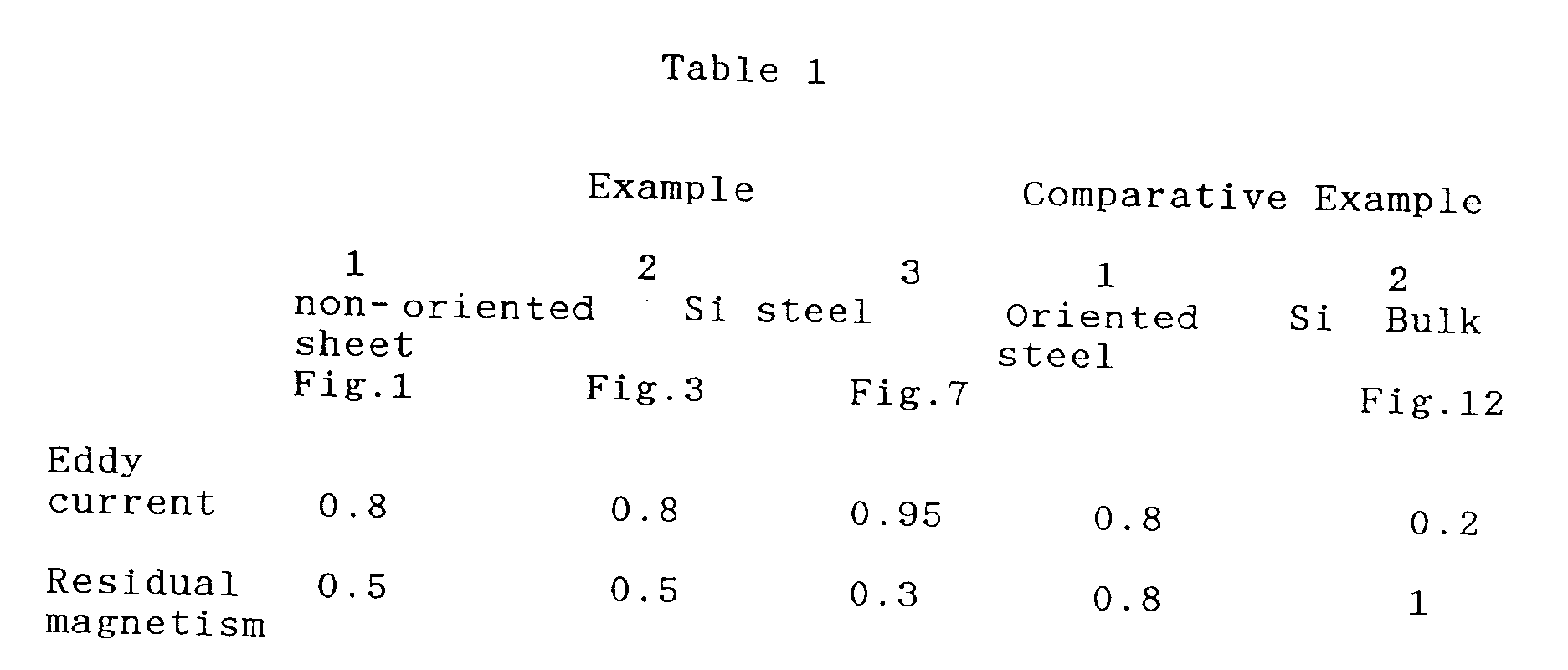
- As apparent from the examples, when the magnetic poles comprising a plurality of block-shaped or bar-shaped magnetic pole members formed by laminating and integrating a plurality of non- oriented steel sheets are used for the magnetic field generating device used for MRI, the magnetic field in the gap can be made uniform and there can be obtained effects of reducing the eddy current caused by the gradient field coils, as well as reducing the residual magnetism caused by GC pulses.
Claims (16)
magnetic poles which have been formed by laminating and integrating a plurality of non-oriented silicon steel sheets are utilized.
the non-oriented silicon steel sheets constituting each block-shaped magnetic pole member are stacked in the direction which extends towards the opposing magnetic pole to form the laminated structure of the pole.
the direction of laminating the non-oriented silicon steel sheets is in perpendicular to the opposing direction of the magnetic poles.
Applications Claiming Priority (4)
| Application Number | Priority Date | Filing Date | Title |
|---|---|---|---|
| JP2261417A JP2649436B2 (en) | 1990-09-29 | 1990-09-29 | Magnetic field generator for MRI |
| JP2261418A JP2649437B2 (en) | 1990-09-29 | 1990-09-29 | Magnetic field generator for MRI |
| JP261417/90 | 1990-09-29 | ||
| JP261418/90 | 1990-09-29 |
Publications (2)
| Publication Number | Publication Date |
|---|---|
| EP0479514A1 true EP0479514A1 (en) | 1992-04-08 |
| EP0479514B1 EP0479514B1 (en) | 1998-07-01 |
Family
ID=26545056
Family Applications (1)
| Application Number | Title | Priority Date | Filing Date |
|---|---|---|---|
| EP91308901A Expired - Lifetime EP0479514B1 (en) | 1990-09-29 | 1991-09-27 | Magnetic field generating device used for MRI |
Country Status (4)
| Country | Link |
|---|---|
| US (1) | US5283544A (en) |
| EP (1) | EP0479514B1 (en) |
| DE (1) | DE69129687T2 (en) |
| SG (1) | SG43224A1 (en) |
Cited By (16)
| Publication number | Priority date | Publication date | Assignee | Title |
|---|---|---|---|---|
| EP0645641A1 (en) * | 1993-09-29 | 1995-03-29 | Oxford Magnet Technology Limited | Improvements in or relating to MRI magnets |
| GB2282451A (en) * | 1993-09-29 | 1995-04-05 | Oxford Magnet Tech | Yoke MRI magnet with radially laminated pole-plates |
| US5555251A (en) * | 1993-06-08 | 1996-09-10 | Picker Nordstar Inc. | Arrangement to minimize eddy currents in MR imagers |
| WO1999052427A1 (en) | 1998-04-14 | 1999-10-21 | Sumitomo Special Metals Co., Ltd. | Magnetic field generating device for mri |
| EP0957369A1 (en) * | 1998-05-11 | 1999-11-17 | Esaote S.p.A. | Magnet structure, particularly for nuclear magnetic resonance imaging machines |
| EP1004888A1 (en) * | 1998-11-24 | 2000-05-31 | General Electric Company | Laminate tiles for an MRI system and method and apparatus for manufacturing the laminate tiles |
| DE19854483A1 (en) * | 1998-11-25 | 2000-06-08 | Siemens Ag | Device to generate magnetic field, for MRI unit; has pair of magnet poles comprising pole plates constructed from layers formed of magnetically conductive plates that are electrically insulated |
| EP1004889A3 (en) * | 1998-11-24 | 2000-08-23 | General Electric Company | Laminate tile pole piece for an MRI magnet, a method of manufacturing the pole piece and a mold for bonding pole piece tiles |
| EP0984461A3 (en) * | 1998-08-31 | 2000-12-06 | General Electric Company | Low eddy current and low hysteresis magnet pole faces in MR imaging |
| EP0999456A3 (en) * | 1998-11-02 | 2001-05-16 | General Electric Company | Magnet having a shim for a laminated pole piece |
| US6586936B2 (en) | 2000-06-15 | 2003-07-01 | Esaote, S.P.A. | Process for manufacturing magnetic field generating devices in nuclear magnetic resonance imaging apparatuses and image generating device according to said process |
| WO2004104612A1 (en) * | 2003-05-23 | 2004-12-02 | Siemens Aktiengesellschaft | Magnetic field generating system applicable to nuclear magnetic resonance device |
| EP1447676A3 (en) * | 2003-02-12 | 2005-09-07 | GE Medical Systems Global Technology Company LLC | Circular pole piece and mri system |
| WO2005101047A1 (en) * | 2004-04-13 | 2005-10-27 | Esaote, S.P.A. | Nuclear magnetic resonance apparatus |
| JP2016096829A (en) * | 2014-11-18 | 2016-05-30 | 株式会社日立製作所 | Magnetic resonance imaging device |
| EP4019995A1 (en) | 2020-12-22 | 2022-06-29 | Bruker BioSpin GmbH | Epr spectrometer with at least one pole piece made at least partially of a function material |
Families Citing this family (38)
| Publication number | Priority date | Publication date | Assignee | Title |
|---|---|---|---|---|
| JP3008615B2 (en) * | 1991-11-15 | 2000-02-14 | 大同特殊鋼株式会社 | Radial anisotropic ring magnet and method of manufacturing the same |
| JP2953659B1 (en) * | 1998-08-06 | 1999-09-27 | 住友特殊金属株式会社 | Magnetic field generator for MRI, method of assembling the same, and method of assembling magnet unit used therein |
| US6331363B1 (en) | 1998-11-06 | 2001-12-18 | Honeywell International Inc. | Bulk amorphous metal magnetic components |
| US6348275B1 (en) * | 1998-11-06 | 2002-02-19 | Honeywell International Inc. | Bulk amorphous metal magnetic component |
| US6346337B1 (en) | 1998-11-06 | 2002-02-12 | Honeywell International Inc. | Bulk amorphous metal magnetic component |
| JP3283242B2 (en) * | 1999-06-21 | 2002-05-20 | ジーイー横河メディカルシステム株式会社 | Gradient coil manufacturing method, gradient coil and MRI apparatus |
| US6552639B2 (en) | 2000-04-28 | 2003-04-22 | Honeywell International Inc. | Bulk stamped amorphous metal magnetic component |
| US7011718B2 (en) * | 2001-04-25 | 2006-03-14 | Metglas, Inc. | Bulk stamped amorphous metal magnetic component |
| US6973711B1 (en) | 2000-05-24 | 2005-12-13 | Fonar Corporation | Method for making pieces for a magnetic resonance imaging magnet |
| US6744342B2 (en) * | 2000-07-27 | 2004-06-01 | Decristofaro Nicholas J. | High performance bulk metal magnetic component |
| US6970061B1 (en) * | 2000-11-22 | 2005-11-29 | Fonar Corporation | Magnet structure |
| US7463129B1 (en) | 2000-11-22 | 2008-12-09 | Fonar Corporation | Magnet structure |
| US7271689B1 (en) | 2000-11-22 | 2007-09-18 | Fonar Corporation | Magnet structure |
| US6982620B1 (en) * | 2000-11-22 | 2006-01-03 | Fonar Corporation | Magnet structure |
| US7248137B1 (en) | 2000-11-22 | 2007-07-24 | Fonar Corporation | Magnet structure |
| US6662434B2 (en) | 2001-04-03 | 2003-12-16 | General Electric Company | Method and apparatus for magnetizing a permanent magnet |
| US6518867B2 (en) | 2001-04-03 | 2003-02-11 | General Electric Company | Permanent magnet assembly and method of making thereof |
| US20040019271A1 (en) * | 2002-07-29 | 2004-01-29 | General Electric Company | Pole pieces for magnetic resonance imaging systems |
| US6737951B1 (en) | 2002-11-01 | 2004-05-18 | Metglas, Inc. | Bulk amorphous metal inductive device |
| US6873239B2 (en) | 2002-11-01 | 2005-03-29 | Metglas Inc. | Bulk laminated amorphous metal inductive device |
| ITSV20030011A1 (en) * | 2003-03-31 | 2004-10-01 | Esaote Spa | MAGNETIC STRUCTURE FOR PURCHASING MACHINES OF |
| US6859123B2 (en) * | 2003-04-03 | 2005-02-22 | Ge Medical Systems Global Technology Company, Llc | Methods and apparatus for positioning permanent magnetic blocks |
| US7235910B2 (en) | 2003-04-25 | 2007-06-26 | Metglas, Inc. | Selective etching process for cutting amorphous metal shapes and components made thereof |
| US20050062572A1 (en) * | 2003-09-22 | 2005-03-24 | General Electric Company | Permanent magnet alloy for medical imaging system and method of making |
| US7423431B2 (en) * | 2003-09-29 | 2008-09-09 | General Electric Company | Multiple ring polefaceless permanent magnet and method of making |
| US7148689B2 (en) | 2003-09-29 | 2006-12-12 | General Electric Company | Permanent magnet assembly with movable permanent body for main magnetic field adjustable |
| US7218195B2 (en) * | 2003-10-01 | 2007-05-15 | General Electric Company | Method and apparatus for magnetizing a permanent magnet |
| US6937018B2 (en) * | 2003-10-31 | 2005-08-30 | General Electric Company | Systems and methods for fabricating pole pieces for magnetic resonance imaging systems |
| US8031853B2 (en) * | 2004-06-02 | 2011-10-04 | Clearone Communications, Inc. | Multi-pod conference systems |
| US7916849B2 (en) * | 2004-06-02 | 2011-03-29 | Clearone Communications, Inc. | Systems and methods for managing the gating of microphones in a multi-pod conference system |
| US7864937B2 (en) * | 2004-06-02 | 2011-01-04 | Clearone Communications, Inc. | Common control of an electronic multi-pod conferencing system |
| US8644525B2 (en) * | 2004-06-02 | 2014-02-04 | Clearone Communications, Inc. | Virtual microphones in electronic conferencing systems |
| EP1808126B1 (en) * | 2004-09-30 | 2012-12-26 | Hitachi Metals, Ltd. | Magnetic field generator for mri |
| US8457614B2 (en) * | 2005-04-07 | 2013-06-04 | Clearone Communications, Inc. | Wireless multi-unit conference phone |
| CN101256221B (en) * | 2007-02-28 | 2010-09-29 | 西门子(中国)有限公司 | A Method for Reducing Eddy Currents Caused by Gradient Magnetic Fields |
| BR112017004336A2 (en) | 2014-09-05 | 2017-12-05 | Hyperfine Res Inc | low field magnetic resonance imaging methods and apparatus |
| EP4336577B1 (en) * | 2022-09-09 | 2026-03-04 | Technische Universität Berlin | Actuator arrangement and method for operating |
| US12099104B2 (en) | 2023-01-20 | 2024-09-24 | Fujifilm Healthcare Americas Corporation | Passive shield for magnetic resonance imaging gradient coils |
Citations (9)
| Publication number | Priority date | Publication date | Assignee | Title |
|---|---|---|---|---|
| US3927397A (en) * | 1974-05-02 | 1975-12-16 | Honeywell Inf Systems | Bias field apparatus for magnetic domain memory device |
| JPS6088407A (en) | 1983-10-19 | 1985-05-18 | Sumitomo Special Metals Co Ltd | Magnetic field generating device |
| EP0170318A1 (en) * | 1984-07-17 | 1986-02-05 | Koninklijke Philips Electronics N.V. | Nuclear magnetic resonance apparatus with a permanent magnet |
| JPS61203605A (en) | 1985-03-07 | 1986-09-09 | Fuji Electric Co Ltd | Magnet having highly uniform magnetic field |
| EP0210120A1 (en) * | 1985-05-23 | 1987-01-28 | Siemens Aktiengesellschaft | Magnet for a nuclear magnetic resonance tomograph |
| JPS6325907A (en) | 1986-07-18 | 1988-02-03 | Toshiba Corp | Magnetic field generating apparatus |
| EP0284439A1 (en) * | 1987-03-27 | 1988-09-28 | Sumitomo Special Metals Co. Ltd. | Magnetic field generating device |
| US4943774A (en) * | 1989-06-01 | 1990-07-24 | General Atomics | Magnetic field control apparatus |
| US4980641A (en) * | 1989-08-11 | 1990-12-25 | General Atomics | Method and apparatus of reducing magnetic hysteresis in MRI systems |
Family Cites Families (6)
| Publication number | Priority date | Publication date | Assignee | Title |
|---|---|---|---|---|
| US4671119A (en) * | 1986-04-21 | 1987-06-09 | D. Halmi And Associates, Inc. | Flow measuring device for partially filled conduits |
| JPS6313306A (en) * | 1986-07-04 | 1988-01-20 | Hitachi Ltd | Electromagnet iron core and manufacture thereof |
| US4827235A (en) * | 1986-07-18 | 1989-05-02 | Kabushiki Kaisha Toshiba | Magnetic field generator useful for a magnetic resonance imaging instrument |
| US4758813A (en) * | 1987-06-24 | 1988-07-19 | Field Effects, Inc. | Cylindrical NMR bias magnet apparatus employing permanent magnets and methods therefor |
| US5061897A (en) * | 1990-03-23 | 1991-10-29 | Fonar Corporation | Eddy current control in magnetic resonance imaging |
| US5124651A (en) * | 1990-10-24 | 1992-06-23 | Fonar Corporation | Nuclear magnetic resonance scanners with composite pole facings |
-
1991
- 1991-09-27 SG SG1996005853A patent/SG43224A1/en unknown
- 1991-09-27 US US07/766,520 patent/US5283544A/en not_active Expired - Lifetime
- 1991-09-27 DE DE69129687T patent/DE69129687T2/en not_active Expired - Lifetime
- 1991-09-27 EP EP91308901A patent/EP0479514B1/en not_active Expired - Lifetime
Patent Citations (9)
| Publication number | Priority date | Publication date | Assignee | Title |
|---|---|---|---|---|
| US3927397A (en) * | 1974-05-02 | 1975-12-16 | Honeywell Inf Systems | Bias field apparatus for magnetic domain memory device |
| JPS6088407A (en) | 1983-10-19 | 1985-05-18 | Sumitomo Special Metals Co Ltd | Magnetic field generating device |
| EP0170318A1 (en) * | 1984-07-17 | 1986-02-05 | Koninklijke Philips Electronics N.V. | Nuclear magnetic resonance apparatus with a permanent magnet |
| JPS61203605A (en) | 1985-03-07 | 1986-09-09 | Fuji Electric Co Ltd | Magnet having highly uniform magnetic field |
| EP0210120A1 (en) * | 1985-05-23 | 1987-01-28 | Siemens Aktiengesellschaft | Magnet for a nuclear magnetic resonance tomograph |
| JPS6325907A (en) | 1986-07-18 | 1988-02-03 | Toshiba Corp | Magnetic field generating apparatus |
| EP0284439A1 (en) * | 1987-03-27 | 1988-09-28 | Sumitomo Special Metals Co. Ltd. | Magnetic field generating device |
| US4943774A (en) * | 1989-06-01 | 1990-07-24 | General Atomics | Magnetic field control apparatus |
| US4980641A (en) * | 1989-08-11 | 1990-12-25 | General Atomics | Method and apparatus of reducing magnetic hysteresis in MRI systems |
Non-Patent Citations (1)
| Title |
|---|
| PATENT ABSTRACTS OF JAPAN vol. 5, no. 15 (E-43)(687) 29 January 1981 & JP-A-55 145 305 ( MATSUSHITA DENKO K.K. ) 12 November 1980 * |
Cited By (27)
| Publication number | Priority date | Publication date | Assignee | Title |
|---|---|---|---|---|
| US5555251A (en) * | 1993-06-08 | 1996-09-10 | Picker Nordstar Inc. | Arrangement to minimize eddy currents in MR imagers |
| GB2282451A (en) * | 1993-09-29 | 1995-04-05 | Oxford Magnet Tech | Yoke MRI magnet with radially laminated pole-plates |
| US5680086A (en) * | 1993-09-29 | 1997-10-21 | Oxford Magnet Technology Limited | MRI magnets |
| GB2282451B (en) * | 1993-09-29 | 1997-11-12 | Oxford Magnet Tech | Improvements in or relating to MRI magnets |
| EP0645641A1 (en) * | 1993-09-29 | 1995-03-29 | Oxford Magnet Technology Limited | Improvements in or relating to MRI magnets |
| WO1999052427A1 (en) | 1998-04-14 | 1999-10-21 | Sumitomo Special Metals Co., Ltd. | Magnetic field generating device for mri |
| EP0998876A4 (en) * | 1998-04-14 | 2005-11-16 | Neomax Co Ltd | MAGNETIC FIELD GENERATOR FOR MRI |
| EP0957369A1 (en) * | 1998-05-11 | 1999-11-17 | Esaote S.p.A. | Magnet structure, particularly for nuclear magnetic resonance imaging machines |
| EP0984461A3 (en) * | 1998-08-31 | 2000-12-06 | General Electric Company | Low eddy current and low hysteresis magnet pole faces in MR imaging |
| EP0999456A3 (en) * | 1998-11-02 | 2001-05-16 | General Electric Company | Magnet having a shim for a laminated pole piece |
| EP1004889A3 (en) * | 1998-11-24 | 2000-08-23 | General Electric Company | Laminate tile pole piece for an MRI magnet, a method of manufacturing the pole piece and a mold for bonding pole piece tiles |
| EP1004888A1 (en) * | 1998-11-24 | 2000-05-31 | General Electric Company | Laminate tiles for an MRI system and method and apparatus for manufacturing the laminate tiles |
| US6215382B1 (en) | 1998-11-25 | 2001-04-10 | Siemens Aktiengesellschaft | Device for generating a magnetic field in an air gap |
| DE19854483A1 (en) * | 1998-11-25 | 2000-06-08 | Siemens Ag | Device to generate magnetic field, for MRI unit; has pair of magnet poles comprising pole plates constructed from layers formed of magnetically conductive plates that are electrically insulated |
| DE19854483B4 (en) * | 1998-11-25 | 2005-02-24 | Siemens Ag | Device for generating a magnetic field in an air gap |
| US6586936B2 (en) | 2000-06-15 | 2003-07-01 | Esaote, S.P.A. | Process for manufacturing magnetic field generating devices in nuclear magnetic resonance imaging apparatuses and image generating device according to said process |
| EP1167989A3 (en) * | 2000-06-15 | 2003-08-13 | Esaote S.p.A. | Process for manufacturing pole pieces of nuclear magnetic resonance imaging magnets |
| EP2108973A1 (en) * | 2000-06-15 | 2009-10-14 | Esaote S.p.A. | Process for manufacturing pole pieces of nuclear magnetic resonance imaging magnets |
| EP2108974A1 (en) * | 2000-06-15 | 2009-10-14 | Esaote S.p.A. | Process for manufacturing pole pieces of nuclear magnetic resonance imaging magnets |
| EP1447676A3 (en) * | 2003-02-12 | 2005-09-07 | GE Medical Systems Global Technology Company LLC | Circular pole piece and mri system |
| CN100419451C (en) * | 2003-02-12 | 2008-09-17 | Ge医疗系统环球技术有限公司 | Round pole pieces in MRI systems |
| CN100434928C (en) * | 2003-05-23 | 2008-11-19 | 西门子(中国)有限公司 | Magnetic field generating system used for magnetic resonance equipment |
| WO2004104612A1 (en) * | 2003-05-23 | 2004-12-02 | Siemens Aktiengesellschaft | Magnetic field generating system applicable to nuclear magnetic resonance device |
| US7453264B2 (en) | 2004-04-13 | 2008-11-18 | Esaote, S.P.A. | Nuclear Magnetic Resonance apparatus |
| WO2005101047A1 (en) * | 2004-04-13 | 2005-10-27 | Esaote, S.P.A. | Nuclear magnetic resonance apparatus |
| JP2016096829A (en) * | 2014-11-18 | 2016-05-30 | 株式会社日立製作所 | Magnetic resonance imaging device |
| EP4019995A1 (en) | 2020-12-22 | 2022-06-29 | Bruker BioSpin GmbH | Epr spectrometer with at least one pole piece made at least partially of a function material |
Also Published As
| Publication number | Publication date |
|---|---|
| EP0479514B1 (en) | 1998-07-01 |
| US5283544A (en) | 1994-02-01 |
| SG43224A1 (en) | 1997-10-17 |
| DE69129687D1 (en) | 1998-08-06 |
| DE69129687T2 (en) | 1999-03-11 |
Similar Documents
| Publication | Publication Date | Title |
|---|---|---|
| US5283544A (en) | Magnetic field generating device used for MRI | |
| EP0691548B1 (en) | Magnetic field generating device for use in MRI | |
| US5252924A (en) | Magnetic field generating apparatus for MRI | |
| US5621324A (en) | Magnetic field generator for MRI | |
| EP0284439B1 (en) | Magnetic field generating device | |
| US5555251A (en) | Arrangement to minimize eddy currents in MR imagers | |
| KR100362042B1 (en) | Magnetic field generating device for mri | |
| EP0645641A1 (en) | Improvements in or relating to MRI magnets | |
| US4656449A (en) | Field modifying elements for an electromagnet having a substantially C-shaped yoke | |
| JPWO1999052427A1 (en) | MRI magnetic field generator | |
| JP2561591B2 (en) | Magnetic field generator for MRI | |
| JP3016544B2 (en) | Permanent magnet magnetic circuit | |
| EP0541872B1 (en) | Magnetic field generating apparatus for MRI | |
| JP2764458B2 (en) | Magnetic field generator for MRI | |
| JP2649436B2 (en) | Magnetic field generator for MRI | |
| JP2649437B2 (en) | Magnetic field generator for MRI | |
| EP1447676B1 (en) | Circular pole piece and mri system | |
| USRE35565E (en) | Magnetic field generating apparatus for MRI | |
| JP3073933B2 (en) | Magnetic field generator for MRI | |
| JP4214736B2 (en) | Magnetic field generator for MRI | |
| JP3445303B2 (en) | Magnetic field generator for MRI | |
| JPH0287505A (en) | Magnetic field generating equipment for mri use | |
| JP3073934B2 (en) | Magnetic field generator for MRI | |
| JPH0563085B2 (en) | ||
| JPH0394733A (en) | Magnetic field generator for mri |
Legal Events
| Date | Code | Title | Description |
|---|---|---|---|
| PUAI | Public reference made under article 153(3) epc to a published international application that has entered the european phase |
Free format text: ORIGINAL CODE: 0009012 |
|
| AK | Designated contracting states |
Kind code of ref document: A1 Designated state(s): DE FR GB IT NL |
|
| RIN1 | Information on inventor provided before grant (corrected) |
Inventor name: AOKI, MASAAKI Inventor name: SAKURAI, HIDEYA |
|
| 17P | Request for examination filed |
Effective date: 19921006 |
|
| 17Q | First examination report despatched |
Effective date: 19950711 |
|
| GRAG | Despatch of communication of intention to grant |
Free format text: ORIGINAL CODE: EPIDOS AGRA |
|
| GRAG | Despatch of communication of intention to grant |
Free format text: ORIGINAL CODE: EPIDOS AGRA |
|
| GRAH | Despatch of communication of intention to grant a patent |
Free format text: ORIGINAL CODE: EPIDOS IGRA |
|
| GRAH | Despatch of communication of intention to grant a patent |
Free format text: ORIGINAL CODE: EPIDOS IGRA |
|
| GRAA | (expected) grant |
Free format text: ORIGINAL CODE: 0009210 |
|
| AK | Designated contracting states |
Kind code of ref document: B1 Designated state(s): DE FR GB IT NL |
|
| REF | Corresponds to: |
Ref document number: 69129687 Country of ref document: DE Date of ref document: 19980806 |
|
| ITF | It: translation for a ep patent filed | ||
| ET | Fr: translation filed | ||
| PLBE | No opposition filed within time limit |
Free format text: ORIGINAL CODE: 0009261 |
|
| STAA | Information on the status of an ep patent application or granted ep patent |
Free format text: STATUS: NO OPPOSITION FILED WITHIN TIME LIMIT |
|
| 26N | No opposition filed | ||
| REG | Reference to a national code |
Ref country code: GB Ref legal event code: IF02 |
|
| PGFP | Annual fee paid to national office [announced via postgrant information from national office to epo] |
Ref country code: GB Payment date: 20100929 Year of fee payment: 20 |
|
| PGFP | Annual fee paid to national office [announced via postgrant information from national office to epo] |
Ref country code: NL Payment date: 20100930 Year of fee payment: 20 Ref country code: FR Payment date: 20101014 Year of fee payment: 20 |
|
| PGFP | Annual fee paid to national office [announced via postgrant information from national office to epo] |
Ref country code: DE Payment date: 20101001 Year of fee payment: 20 |
|
| PG25 | Lapsed in a contracting state [announced via postgrant information from national office to epo] |
Ref country code: IT Free format text: LAPSE BECAUSE OF NON-PAYMENT OF DUE FEES Effective date: 20090927 |
|
| PGFP | Annual fee paid to national office [announced via postgrant information from national office to epo] |
Ref country code: IT Payment date: 20100929 Year of fee payment: 20 |
|
| PGRI | Patent reinstated in contracting state [announced from national office to epo] |
Ref country code: IT Effective date: 20110616 |
|
| REG | Reference to a national code |
Ref country code: DE Ref legal event code: R071 Ref document number: 69129687 Country of ref document: DE |
|
| REG | Reference to a national code |
Ref country code: DE Ref legal event code: R071 Ref document number: 69129687 Country of ref document: DE |
|
| REG | Reference to a national code |
Ref country code: NL Ref legal event code: V4 Effective date: 20110927 |
|
| REG | Reference to a national code |
Ref country code: GB Ref legal event code: PE20 Expiry date: 20110926 |
|
| PG25 | Lapsed in a contracting state [announced via postgrant information from national office to epo] |
Ref country code: GB Free format text: LAPSE BECAUSE OF EXPIRATION OF PROTECTION Effective date: 20110926 |
|
| PG25 | Lapsed in a contracting state [announced via postgrant information from national office to epo] |
Ref country code: NL Free format text: LAPSE BECAUSE OF EXPIRATION OF PROTECTION Effective date: 20110927 |
|
| PG25 | Lapsed in a contracting state [announced via postgrant information from national office to epo] |
Ref country code: DE Free format text: LAPSE BECAUSE OF EXPIRATION OF PROTECTION Effective date: 20110928 |