EP0479469A2 - Trägeranordnung für einen drehbaren Isolator - Google Patents
Trägeranordnung für einen drehbaren Isolator Download PDFInfo
- Publication number
- EP0479469A2 EP0479469A2 EP91308678A EP91308678A EP0479469A2 EP 0479469 A2 EP0479469 A2 EP 0479469A2 EP 91308678 A EP91308678 A EP 91308678A EP 91308678 A EP91308678 A EP 91308678A EP 0479469 A2 EP0479469 A2 EP 0479469A2
- Authority
- EP
- European Patent Office
- Prior art keywords
- bearing
- combination
- insulator
- further characterised
- support mounting
- Prior art date
- Legal status (The legal status is an assumption and is not a legal conclusion. Google has not performed a legal analysis and makes no representation as to the accuracy of the status listed.)
- Granted
Links
- 239000012212 insulator Substances 0.000 title claims abstract description 37
- 229920000049 Carbon (fiber) Polymers 0.000 claims description 2
- 239000004917 carbon fiber Substances 0.000 claims description 2
- 229920001903 high density polyethylene Polymers 0.000 claims description 2
- 239000004700 high-density polyethylene Substances 0.000 claims description 2
- VNWKTOKETHGBQD-UHFFFAOYSA-N methane Chemical compound C VNWKTOKETHGBQD-UHFFFAOYSA-N 0.000 claims 1
- 230000002939 deleterious effect Effects 0.000 abstract description 5
- 230000006866 deterioration Effects 0.000 abstract description 5
- 239000000463 material Substances 0.000 description 4
- 239000004020 conductor Substances 0.000 description 2
- 230000013011 mating Effects 0.000 description 2
- 229910052751 metal Inorganic materials 0.000 description 2
- 238000012986 modification Methods 0.000 description 2
- 230000004048 modification Effects 0.000 description 2
- 229920000642 polymer Polymers 0.000 description 2
- 230000005540 biological transmission Effects 0.000 description 1
- 230000007797 corrosion Effects 0.000 description 1
- 238000005260 corrosion Methods 0.000 description 1
- 230000000694 effects Effects 0.000 description 1
- 239000000835 fiber Substances 0.000 description 1
- 239000002184 metal Substances 0.000 description 1
- 150000002739 metals Chemical class 0.000 description 1
- 238000000034 method Methods 0.000 description 1
- 230000008520 organization Effects 0.000 description 1
- 239000011347 resin Substances 0.000 description 1
- 229920005989 resin Polymers 0.000 description 1
Images
Classifications
-
- H—ELECTRICITY
- H01—ELECTRIC ELEMENTS
- H01B—CABLES; CONDUCTORS; INSULATORS; SELECTION OF MATERIALS FOR THEIR CONDUCTIVE, INSULATING OR DIELECTRIC PROPERTIES
- H01B17/00—Insulators or insulating bodies characterised by their form
- H01B17/02—Suspension insulators; Strain insulators
- H01B17/06—Fastening of insulator to support, to conductor, or to adjoining insulator
-
- H—ELECTRICITY
- H01—ELECTRIC ELEMENTS
- H01H—ELECTRIC SWITCHES; RELAYS; SELECTORS; EMERGENCY PROTECTIVE DEVICES
- H01H33/00—High-tension or heavy-current switches with arc-extinguishing or arc-preventing means
- H01H33/02—Details
-
- H—ELECTRICITY
- H01—ELECTRIC ELEMENTS
- H01B—CABLES; CONDUCTORS; INSULATORS; SELECTION OF MATERIALS FOR THEIR CONDUCTIVE, INSULATING OR DIELECTRIC PROPERTIES
- H01B17/00—Insulators or insulating bodies characterised by their form
- H01B17/14—Supporting insulators
- H01B17/16—Fastening of insulators to support, to conductor, or to adjoining insulator
-
- H—ELECTRICITY
- H01—ELECTRIC ELEMENTS
- H01H—ELECTRIC SWITCHES; RELAYS; SELECTORS; EMERGENCY PROTECTIVE DEVICES
- H01H33/00—High-tension or heavy-current switches with arc-extinguishing or arc-preventing means
- H01H33/02—Details
- H01H33/04—Means for extinguishing or preventing arc between current-carrying parts
- H01H33/12—Auxiliary contacts on to which the arc is transferred from the main contacts
- H01H33/121—Load break switches
- H01H33/125—Load break switches comprising a separate circuit breaker
- H01H33/127—Load break switches comprising a separate circuit breaker movable with a sectionalising contact arm and operated by such movement
-
- H—ELECTRICITY
- H01—ELECTRIC ELEMENTS
- H01H—ELECTRIC SWITCHES; RELAYS; SELECTORS; EMERGENCY PROTECTIVE DEVICES
- H01H33/00—High-tension or heavy-current switches with arc-extinguishing or arc-preventing means
- H01H33/02—Details
- H01H33/24—Means for preventing discharge to non-current-carrying parts, e.g. using corona ring
Definitions
- the present invention relates generally to the field of insulators and switches, and more particularly to a support arrangement for an insulator including a non-metallic element of suitable conductivity to permit the flow of leakage current as well as capacitive charging current through the element.
- the top of the insulator carries a conductor at one potential and the bottom of the insulator is rotatably supported with respect to a support surface at a second potential.
- the insulator is fabricated from a polymeric material, it is desirable to provide a low friction interface between the insulator and the support surface to minimize operating forces and to avoid wearing of the insulator. Such wear could detract from the proper alignment of the insulator.
- a bearing which may also be referred to as a bushing.
- a metallic bearing may be utilized, polymeric materials offer lower frictional characteristics and no corrosion effects.
- sufficient voltage may be developed across the bearing such that the resulting leakage currents and capacitive charging currents can cause tracking across and/or deterioration of the bearing.
- a durable polymeric bearing for a rotatable support insulator is of sufficient conductivity to permit the flow of leakage current and capacitive charging current through the bearing. Thus, tracking across and/or deterioration of the bearing is avoided since insufficient voltage is developed across the bearing to cause any deleterious effects.
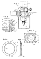
- the stress-relieving arrangement of the present invention is illustrated for a support insulator 10.
- the support insulator 10 is rotatably supported with respect to a support member 12.
- the support insulator 10 includes and defines a vertical upstanding section of a rotatable interrupter switch, the support insulator 10 being rotatable to provide a disconnect function.
- the support insulator 10 is molded from a polymeric compound, for example, cycloaliphatic resin.
- the support insulator 10 is molded to define a bore 14 and various external characteristics including bearing surfaces at the lower end thereof. Specifically, as best seen in FIG. 2, a circumferential bearing surface 16 and a shoulder 18 are defined.
- an operating rod 20 is disposed through the bore 14 for operation of an interrupter linkage (not shown).
- the support mounting 12 includes a receiving arrangement including a circular opening 22 to receive the insulator.
- the receiving arrangement also includes a shoulder or necked-down portion 23 and a rim 24.
- an appropriate bearing surface i.e., low frictional characteristics
- the support mounting 12 and the support insulator 10 are desirable between the support mounting 12 and the support insulator 10 to minimize operating effort and to ensure against deleterious wearing of the polymeric compound at the bearing surfaces 16 and 18. If a suitable bearing surface is not provided, the wear could detract from the proper alignment of the support insulator 10.
- the top of the support insulator 10 is connected to a conductor at a first potential and the support mounting 12 is maintained at a second potential. If a non-metallic bearing 30 is provided between the support insulator 10 and the support mounting 12, sufficient voltage may be developed cross the bearing 30 to cause tracking across and/or deterioration of the bearing 30.
- a non-metallic conductive bearing 30 is provided within the support mounting 12 to cooperate with the bearing surfaces 16,18 of the support insulator 10.
- the bearing 30 (which may also be referred to as a bushing) includes a circumferential bearing surface 32 in the shape of an annular disk and a sleeve (cylindrical) bearing surface 34 for appropriate engagement with the respective bearing surfaces 16, 18 of the support insulator 10.
- the bearing 30 also includes a curved projection 36 on the outer periphery of the sleeve portion 34 to cooperate with a mating receiving notch 38 formed into the inner periphery of the opening 22 of the support mounting 12.
- the notch 38 and projection 36 locate and affix the conductive bearing ring 30 within the support mounting 12 to ensure that there is no relative rotation between the support mounting 12 and the conductive bearing ring 30. Thus, relative rotation occurs as desired between the bearing surfaces 16, 18 of the support insulator 10 and the bearing 30.
- the bearing 30 is suitably dimensioned along with the opening 22, the portion 23, and the rim 24 of the support mounting 12 for desirable mating relationships. Also in a preferred embodiment, the bearing 30 includes a gap 40 so as to define a split-ring configuration. This configuration facilitates the appropriate affixing of the bearing 30 within the support mounting 12 and liberalizes the dimensional tolerances for the interfitting portions of the bearing 30 and the support mounting 12.
- the bearing 30 While the term conductive is utilized to describe the bearing 30, it should be realized that conductivity on the order of metals is not required. The degree of conductivity is determined by the particular components and operating voltages. Thus, the bearing 30 is of suitable predetermined conductivity to avoid deleterious effects. In a specific example for a switch rated at 15 kV, the bearing 30 is suitably fabricated from a high-density polyethylene and is fiber-filled with carbon fibers to achieve a volume resistivity on the order of approximately 1,000 ohm-cm (per ASTM D257). A suitable material from which the bearing 30 may be fabricated is available from the RTP Co. of Winona, Minnesota, under the designation ESD-C-780.
Landscapes
- Insulators (AREA)
- Rolling Contact Bearings (AREA)
- Fluid-Damping Devices (AREA)
- Fittings On The Vehicle Exterior For Carrying Loads, And Devices For Holding Or Mounting Articles (AREA)
- Mechanisms For Operating Contacts (AREA)
- Discharging, Photosensitive Material Shape In Electrophotography (AREA)
- Motor Or Generator Frames (AREA)
Applications Claiming Priority (2)
| Application Number | Priority Date | Filing Date | Title |
|---|---|---|---|
| US07/590,727 US5252780A (en) | 1989-03-30 | 1990-10-01 | Support arrangement for a rotatable insulator |
| US590727 | 1990-10-01 |
Publications (3)
| Publication Number | Publication Date |
|---|---|
| EP0479469A2 true EP0479469A2 (de) | 1992-04-08 |
| EP0479469A3 EP0479469A3 (en) | 1993-01-13 |
| EP0479469B1 EP0479469B1 (de) | 1995-12-13 |
Family
ID=24363445
Family Applications (1)
| Application Number | Title | Priority Date | Filing Date |
|---|---|---|---|
| EP91308678A Expired - Lifetime EP0479469B1 (de) | 1990-10-01 | 1991-09-24 | Trägeranordnung für einen drehbaren Isolator |
Country Status (6)
| Country | Link |
|---|---|
| US (1) | US5252780A (de) |
| EP (1) | EP0479469B1 (de) |
| KR (1) | KR100212123B1 (de) |
| AT (1) | ATE131657T1 (de) |
| CA (1) | CA2051335C (de) |
| DE (1) | DE69115425T2 (de) |
Cited By (1)
| Publication number | Priority date | Publication date | Assignee | Title |
|---|---|---|---|---|
| WO2017042043A1 (en) * | 2015-09-11 | 2017-03-16 | Abb Schweiz Ag | Fastening device for a cable termination and arrangement comprising fastening device and cable termination |
Families Citing this family (6)
| Publication number | Priority date | Publication date | Assignee | Title |
|---|---|---|---|---|
| US6474941B2 (en) | 2000-12-08 | 2002-11-05 | General Electric Company | Variable stator vane bushing |
| US8222194B2 (en) * | 2008-05-09 | 2012-07-17 | Rhodia Operations | Cleaning compositions incorporating green solvents and methods for use |
| CA2723919A1 (en) * | 2008-05-09 | 2009-11-12 | Rhodia Operations | Cleaning compositions incorporating green solvents and methods for use |
| CA2778222A1 (en) * | 2009-10-19 | 2011-04-28 | Rhodia Operations | Auto-emulsifying cleaning systems and methods for use |
| AU2011338993B2 (en) | 2010-12-10 | 2015-01-29 | Rhodia Operations | Dibasic esters utilized as terpene co-solvents, substitutes and/or carriers in tar sand/bitumen/asphaltene cleaning applications |
| CA2873685C (en) | 2012-04-17 | 2020-06-02 | Rhodia Operations | Polysaccharide slurries with environmentally friendly activator solvents |
Family Cites Families (11)
| Publication number | Priority date | Publication date | Assignee | Title |
|---|---|---|---|---|
| US2790024A (en) * | 1952-06-13 | 1957-04-23 | Du Mont Allen B Lab Inc | Electrical insulator |
| FR2096589B1 (de) * | 1970-06-30 | 1977-01-28 | Siemens Ag | |
| US4134175A (en) * | 1977-09-01 | 1979-01-16 | Liquid Controls Corporation | Non-rotating bushing |
| US4357504A (en) * | 1980-12-24 | 1982-11-02 | Cleaveland/Price Enterprises, Inc. | Bearing and journal means for the rotatable crank-arm assembly of a disconnecting switch |
| US4584429A (en) * | 1983-03-21 | 1986-04-22 | Cooper Industries, Inc. | Electrical assembly including a metal enclosure and a high voltage bushing |
| FR2553592B1 (fr) * | 1983-10-18 | 1985-12-27 | Cables De Lyon Geoffroy Delore | Montage d'extremite pour cable electrique haute tension |
| US4596906A (en) * | 1985-04-10 | 1986-06-24 | S&C Electric Company | Arrangement for providing independent rotary and linear drive outputs for high-voltage switches |
| GB2214575B (en) * | 1988-01-20 | 1992-05-20 | Xerox Corp | Magnetic brush development apparatus. |
| DE3825407A1 (de) * | 1988-07-27 | 1990-02-01 | Sachsenwerk Ag | Schaltkammer eines vakuumschalters |
| US4932795A (en) * | 1988-11-10 | 1990-06-12 | Outboard Marine Corporation | Electrically conductive plastic bushings for marine propulsion devices |
| US4983792A (en) * | 1989-03-30 | 1991-01-08 | S&C Electric Company | Interrupter switch with selective circuit-isolating feature |
-
1990
- 1990-10-01 US US07/590,727 patent/US5252780A/en not_active Expired - Lifetime
-
1991
- 1991-09-13 CA CA002051335A patent/CA2051335C/en not_active Expired - Fee Related
- 1991-09-24 DE DE69115425T patent/DE69115425T2/de not_active Expired - Fee Related
- 1991-09-24 AT AT91308678T patent/ATE131657T1/de not_active IP Right Cessation
- 1991-09-24 EP EP91308678A patent/EP0479469B1/de not_active Expired - Lifetime
- 1991-09-30 KR KR1019910017058A patent/KR100212123B1/ko not_active Expired - Fee Related
Cited By (2)
| Publication number | Priority date | Publication date | Assignee | Title |
|---|---|---|---|---|
| WO2017042043A1 (en) * | 2015-09-11 | 2017-03-16 | Abb Schweiz Ag | Fastening device for a cable termination and arrangement comprising fastening device and cable termination |
| US10164420B2 (en) | 2015-09-11 | 2018-12-25 | Nkt Hv Cables Gmbh | Fastening device for a cable termination and arrangement comprising fastening device and cable termination |
Also Published As
| Publication number | Publication date |
|---|---|
| EP0479469B1 (de) | 1995-12-13 |
| DE69115425D1 (de) | 1996-01-25 |
| CA2051335C (en) | 2001-08-21 |
| CA2051335A1 (en) | 1992-04-02 |
| EP0479469A3 (en) | 1993-01-13 |
| KR100212123B1 (ko) | 1999-08-02 |
| DE69115425T2 (de) | 1996-05-02 |
| US5252780A (en) | 1993-10-12 |
| KR920008784A (ko) | 1992-05-28 |
| ATE131657T1 (de) | 1995-12-15 |
Similar Documents
| Publication | Publication Date | Title |
|---|---|---|
| KR0168833B1 (ko) | 진공차단기 | |
| JPH05500027A (ja) | プラズマアークトーチのための空気―電気式急速脱着コネクタ | |
| EP0479469B1 (de) | Trägeranordnung für einen drehbaren Isolator | |
| KR970031174A (ko) | 교류 발전기(ac generator) | |
| JPS5812966B2 (ja) | 真空スイッチ | |
| EP0840339A3 (de) | Vakuumschalter mit Lichtbogenstreuenden Kontakte | |
| KR930011829B1 (ko) | 진공 차단기 | |
| JPS6346540B2 (de) | ||
| EP0854545A1 (de) | Isolierkappe für Lastunterbrechnungsbuchse | |
| US6462295B1 (en) | High-voltage power circuit breaker comprising an insulating nozzle | |
| CA1077100A (en) | Disconnect contact assembly for metal-clad switchgear and the like | |
| US3715543A (en) | Rotary electrical switching contact assembly with hollow insulating arc barrier | |
| US4721829A (en) | Gas insulated transmission line with shielded electrical joint assembly | |
| CA2231304C (en) | Insulated type switchgear device | |
| EP0012522B1 (de) | Elektrische Schaltanlage | |
| GB2331855A (en) | Transformer with regulating means | |
| HU201171B (en) | Cylindrical tap selector with a contact bridge guided by a cantilever made of insulating material | |
| EP1103988A2 (de) | Durchführungsisolator mit Halbkapazitätsgradienten und mit Isoliergasfüllung, wie SF6 | |
| US2931999A (en) | Multiple collector ring assembly | |
| US3892461A (en) | Load-break connector | |
| EP0011972B1 (de) | Elektrische Schaltanlage | |
| GB2174549A (en) | High current switch contacts | |
| EP0135380A2 (de) | Lastunterbrechungsbuchse und Lösch- und Kontaktanlage dafür | |
| US3966294A (en) | Adaptor for transformer bushing terminals | |
| GB2188487A (en) | Arcing electrode for switch |
Legal Events
| Date | Code | Title | Description |
|---|---|---|---|
| PUAI | Public reference made under article 153(3) epc to a published international application that has entered the european phase |
Free format text: ORIGINAL CODE: 0009012 |
|
| AK | Designated contracting states |
Kind code of ref document: A2 Designated state(s): AT BE CH DE FR GB IT LI NL SE |
|
| PUAL | Search report despatched |
Free format text: ORIGINAL CODE: 0009013 |
|
| AK | Designated contracting states |
Kind code of ref document: A3 Designated state(s): AT BE CH DE FR GB IT LI NL SE |
|
| 17P | Request for examination filed |
Effective date: 19930706 |
|
| 17Q | First examination report despatched |
Effective date: 19940426 |
|
| GRAA | (expected) grant |
Free format text: ORIGINAL CODE: 0009210 |
|
| AK | Designated contracting states |
Kind code of ref document: B1 Designated state(s): AT BE CH DE FR GB IT LI NL SE |
|
| PG25 | Lapsed in a contracting state [announced via postgrant information from national office to epo] |
Ref country code: IT Free format text: LAPSE BECAUSE OF FAILURE TO SUBMIT A TRANSLATION OF THE DESCRIPTION OR TO PAY THE FEE WITHIN THE PRE;WARNING: LAPSES OF ITALIAN PATENTS WITH EFFECTIVE DATE BEFORE 2007 MAY HAVE OCCURRED AT ANY TIME BEFORE 2007. THE CORRECT EFFECTIVE DATE MAY BE DIFFERENT FROM THE ONE RECORDED.SCRIBED TIME-LIMIT Effective date: 19951213 Ref country code: NL Free format text: LAPSE BECAUSE OF FAILURE TO SUBMIT A TRANSLATION OF THE DESCRIPTION OR TO PAY THE FEE WITHIN THE PRESCRIBED TIME-LIMIT Effective date: 19951213 Ref country code: AT Effective date: 19951213 |
|
| REF | Corresponds to: |
Ref document number: 131657 Country of ref document: AT Date of ref document: 19951215 Kind code of ref document: T |
|
| REF | Corresponds to: |
Ref document number: 69115425 Country of ref document: DE Date of ref document: 19960125 |
|
| REG | Reference to a national code |
Ref country code: CH Ref legal event code: NV Representative=s name: SCHMAUDER & WANN PATENTANWALTSBUERO, INHABER KLAUS |
|
| ET | Fr: translation filed | ||
| PG25 | Lapsed in a contracting state [announced via postgrant information from national office to epo] |
Ref country code: SE Effective date: 19960313 |
|
| NLV1 | Nl: lapsed or annulled due to failure to fulfill the requirements of art. 29p and 29m of the patents act | ||
| PLBE | No opposition filed within time limit |
Free format text: ORIGINAL CODE: 0009261 |
|
| STAA | Information on the status of an ep patent application or granted ep patent |
Free format text: STATUS: NO OPPOSITION FILED WITHIN TIME LIMIT |
|
| 26N | No opposition filed | ||
| REG | Reference to a national code |
Ref country code: GB Ref legal event code: IF02 |
|
| PGFP | Annual fee paid to national office [announced via postgrant information from national office to epo] |
Ref country code: FR Payment date: 20080915 Year of fee payment: 18 |
|
| PGFP | Annual fee paid to national office [announced via postgrant information from national office to epo] |
Ref country code: GB Payment date: 20080924 Year of fee payment: 18 |
|
| PGFP | Annual fee paid to national office [announced via postgrant information from national office to epo] |
Ref country code: DE Payment date: 20081002 Year of fee payment: 18 Ref country code: CH Payment date: 20081016 Year of fee payment: 18 |
|
| PGFP | Annual fee paid to national office [announced via postgrant information from national office to epo] |
Ref country code: BE Payment date: 20080922 Year of fee payment: 18 |
|
| BERE | Be: lapsed |
Owner name: *S & C ELECTRIC CY Effective date: 20090930 |
|
| REG | Reference to a national code |
Ref country code: CH Ref legal event code: PL |
|
| GBPC | Gb: european patent ceased through non-payment of renewal fee |
Effective date: 20090924 |
|
| REG | Reference to a national code |
Ref country code: FR Ref legal event code: ST Effective date: 20100531 |
|
| PG25 | Lapsed in a contracting state [announced via postgrant information from national office to epo] |
Ref country code: FR Free format text: LAPSE BECAUSE OF NON-PAYMENT OF DUE FEES Effective date: 20090930 Ref country code: DE Free format text: LAPSE BECAUSE OF NON-PAYMENT OF DUE FEES Effective date: 20100401 |
|
| PG25 | Lapsed in a contracting state [announced via postgrant information from national office to epo] |
Ref country code: BE Free format text: LAPSE BECAUSE OF NON-PAYMENT OF DUE FEES Effective date: 20090930 |
|
| PG25 | Lapsed in a contracting state [announced via postgrant information from national office to epo] |
Ref country code: CH Free format text: LAPSE BECAUSE OF NON-PAYMENT OF DUE FEES Effective date: 20090930 Ref country code: LI Free format text: LAPSE BECAUSE OF NON-PAYMENT OF DUE FEES Effective date: 20090930 |
|
| PG25 | Lapsed in a contracting state [announced via postgrant information from national office to epo] |
Ref country code: GB Free format text: LAPSE BECAUSE OF NON-PAYMENT OF DUE FEES Effective date: 20090924 |