EP0479057A2 - Band conveying device with vacuum attraction mechanism - Google Patents
Band conveying device with vacuum attraction mechanism Download PDFInfo
- Publication number
- EP0479057A2 EP0479057A2 EP91115950A EP91115950A EP0479057A2 EP 0479057 A2 EP0479057 A2 EP 0479057A2 EP 91115950 A EP91115950 A EP 91115950A EP 91115950 A EP91115950 A EP 91115950A EP 0479057 A2 EP0479057 A2 EP 0479057A2
- Authority
- EP
- European Patent Office
- Prior art keywords
- vacuum
- band
- pads
- conveying device
- holding units
- Prior art date
- Legal status (The legal status is an assumption and is not a legal conclusion. Google has not performed a legal analysis and makes no representation as to the accuracy of the status listed.)
- Granted
Links
Images




Classifications
-
- B—PERFORMING OPERATIONS; TRANSPORTING
- B29—WORKING OF PLASTICS; WORKING OF SUBSTANCES IN A PLASTIC STATE IN GENERAL
- B29D—PRODUCING PARTICULAR ARTICLES FROM PLASTICS OR FROM SUBSTANCES IN A PLASTIC STATE
- B29D30/00—Producing pneumatic or solid tyres or parts thereof
- B29D30/06—Pneumatic tyres or parts thereof (e.g. produced by casting, moulding, compression moulding, injection moulding, centrifugal casting)
- B29D30/52—Unvulcanised treads, e.g. on used tyres; Retreading
- B29D30/58—Applying bands of rubber treads, i.e. applying camel backs
-
- B—PERFORMING OPERATIONS; TRANSPORTING
- B29—WORKING OF PLASTICS; WORKING OF SUBSTANCES IN A PLASTIC STATE IN GENERAL
- B29D—PRODUCING PARTICULAR ARTICLES FROM PLASTICS OR FROM SUBSTANCES IN A PLASTIC STATE
- B29D30/00—Producing pneumatic or solid tyres or parts thereof
- B29D30/06—Pneumatic tyres or parts thereof (e.g. produced by casting, moulding, compression moulding, injection moulding, centrifugal casting)
- B29D30/08—Building tyres
- B29D30/20—Building tyres by the flat-tyre method, i.e. building on cylindrical drums
- B29D30/24—Drums
- B29D30/26—Accessories or details, e.g. membranes, transfer rings
- B29D30/2607—Devices for transferring annular tyre components during the building-up stage, e.g. from the first stage to the second stage building drum
Definitions
- This invention relates to a band conveying device for use with a tire forming machine.
- a band is formed by winding a belt-shaped material around a cylindrical drum.
- the so-called vacuum attractor (vacuum pad) is effective in attracting a smooth surface, but not for a rough surface having a stepped portion. The reason is that the vacuum attractor cannot fit with a stepped surface portion of a member to be attracted, leaving a gap between them, so that air is sucked through the gap, disabling vacuum attraction. Since a plurality of vacuum attractors are usually connected together by one pipeline, if at least one vacuum attractor becomes disabled, the others cannot get sufficient vacuum and attain their function.
- each resulting joined portion of the material causes roughness in the form of a stepped portion. Since the position of such a stepped portion can be detected, it is possible to position the vacuum attractors so as not to confront the stepped portion.
- the belt-shaped material is usually formed by joining a plurality of material segments of given length, and each resulting joined portion causes roughness in the form of another stepped portion. Such another stepped portion can hardly be detected by the forming machine. Even if this second type of stepped portion can be detected, it is very difficult to position the vacuum attractors so as not to confront the two types of stepped portions. Consequently, the band cannot be conveyed reliably.
- the present invention provides a band conveying device with vacuum attraction mechanism which comprises a base frame extending between a band forming station and a tire assembling station, a traveling carriage movable on the base frame, a plurality of band holding units provided on the traveling carriage perpendicularly with respect to the traveling direction thereof, and a plurality of vacuum pads for attracting and holding a band by vacuum which are arranged in annular form and attached to the band holding units, and is characterized in that the vacuum pads are divided into at least two vacuum systems, and each of at least two vacuum systems is provided with a vacuum pressure switch and an electromagnetic valve for shutting off its vacuum system when its degree of vacuum decreases below a given level.
- the vacuum pads are divided into at least two vacuum systems, and vacuum is applied to the individual vacuum systems.
- vacuum is applied to the individual vacuum systems.
- the degree of vacuum of any vacuum system cannot reach a given level, vacuum supply to such a malfunctioning vacuum system is shut off, and the other vacuum systems (with sufficient vacuum) are used in band conveying.
- a joined portion arising in the process of a tire forming machine can be put aside.
- the joined portion of a material appears at only one point along the circumference; therefore, even when the said joined portion of a material causes one vacuum system to get insufficient vacuum, the other vacuum systems can well attract the band by vacuum, whereby the band can be conveyed reliably.
- A designates a band holding unit, C a traveling carriage, D a base frame, 2 a band, B2, B3, B4 electromagnetic valves, B5, B6 vacuum pressure switches, and A17, A21, A22 vacuum pads.
- each band holding unit A is slidably supported via a rectilinear bearing C1 and a rail C2 on the traveling carriage C.
- the three band holding units are moved on the traveling carriage C by a driving unit of the positionable type (not shown).
- a frame A1 is secured on the rectilinear bearing C1, a cam A2 is fitted in the frame A1, and pins A3 and A4 are secured to the cam A2.
- a pin A5 is secured to the cam A2, and a plurality of grooves A6 are formed.
- a driving unit of the positionable type A8 is pivotably supported via a pin A10 by a bracket A7 attached to the frame A1, and a clevis A9 at the end of a rod A11 of the driving unit A8 is pivotably supported by the pin A5.
- the frame A1 has a nut A13 attached thereto, and a screw rod A12 is threaded into the nut A13. This screw rod A12 is attached via a bearing (not shown) to the traveling carriage.
- a plurality of levers A14 are pivotably supported by pins A3, and one end A16 of each lever A14 is inserted in the corresponding groove A6 of the cam A2.
- a plurality of levers A15 are pivotably supported by pins A4 secured to the frame A1.
- Fig. 3 shows the band holding unit disposed at either end, in which a vacuum pad A17 is secured to a corresponding block A24, each block A24 has pins A18 and A19 secured thereto, and the corresponding levers A14 and A15 are pivotably supported.
- the distance between the pins A3 and A19 of the lever A14 is equal to that between the pins A4 and A18 of the lever A15.
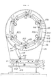
- Fig. 2 shows the band holding unit disposed at the center, in which the vacuum pads A21 and A22 are arranged in the circumferential direction and secured to a corresponding block A23 as illustrated, and the pins A18 and A19 are secured to each block A23.
- the support mechanism of the block A23 is identical with that illustrated in Fig. 3.
- the vacuum pads A17 of the band holding units disposed at either end are connected together by branch lines extending from one pipeline, and actuated/deactuated by the electromagnetic valve B2.
- the vacuum pads A21 and A22 of the band holding unit disposed at the center are actuated/ deactuated by the electromagnetic valves B3 and B4, respectively.
- Vacuum for the electromagnetic valves B3 and B4 is supplied from the output end of the electromagnetic valve B2.
- the output ends of the electromagnetic valves B3 and B4 are connected to the vacuum pressure switches B5 and B6, respectively.
- the electromagnetic valve B2 When the band is to be held, first, the electromagnetic valve B2 is turned on to actuate the vacuum pads A17. Then, the electromagnetic valve B3 is turned on.
- the pressure switch B5 monitors and determines whether or not sufficient vacuum is reached. When sufficient vacuum is reached, the electromagnetic valve B3 is kept on; otherwise, the electromagnetic valve B3 is turned off. Then, the electromagnetic valve B4 is turned on.
- the pressure switch B6 monitors and determines whether or not sufficient vacuum is reached. When sufficient vacuum is reached, the electromagnetic valve B4 is kept on; otherwise, the electromagnetic valve B4 is turned off.
- a band conveying device holds and conveys the cylindrical band 2 by means of the vacuum pads A17, A21 and A22.
- the band 2 is composed of side walls B7, an inner liner B8, and a ply B9, these being arranged in laminated form.
- the vacuum pads A17 come into contact with the side walls, and the vacuum pads A21 and A22 come into contact with the ply. Since the side wall as well as the ply is formed by winding a belt-shaped rubber material into a cylindrical shape, they have joined portions arising in a forming step as shown in Fig. 6.
- B10 designates a joined portion of the side wall
- B11 designates a joined portion of the ply.
- the joined portions arising in the forming step are circumferentially distributed such that they are out of phase or take a phase difference of 90* or 180" therebetween. That is, the joined portions of the side wall and the ply can be distributed so as not to be positionally aligned with the vacuum pads. If such provisions are not incorporated, air leaks through between the vacuum pad and the joined portion (having a rough surface) in contact therewith, resulting in insufficient vacuum.
- the side wall B7 is formed by extrusion, its belt-shaped material before a winding step has no joined portion.
- the ply B9 is formed by connecting a plurality of strip-shaped material segments of given length, its belt-shaped material before the winding step has several joined portions. After the belt-shaped material is wound into a band shape, at least one joined portion (having arisen before the winding step) probably remains on the band. This primary joined portion differs from the joined portion arising in the forming step; thus, it is generally impossible to put the vacuum pad out of alignment with the primary joined portion.
- the holding unit disposed at the center for holding the ply B9 has only one vacuum system of vacuum pads as in the prior art, if the joined portion is aligned with one vacuum pad, the central band-holding unit cannot attain its holding function. Further, if the capacity of a vacuum source is critical, the other vacuum pads cannot get sufficient vacuum, making band conveying impossible.
- the vacuum pads of the central band-holding unit are circumferentially arranged in paired form and divided into two vacuum systems. Consequently, when the joined portion (arising before the winding step) is aligned with the vacuum pad by any chance, the one vacuum system inclusive of the above vacuum pad is put out of use and the other vacuum system is put in use, whereby the band can be held and conveyed reliably.
- Fig. 6 shows the state wherein a primary joined portion B12 different from the joined portion arising in the forming step is in alignment with the vacuum pad A22.
- the electromagnetic valve B4 is turned off, so that the band is held by the vacuum pads A17 and A21.
- an alarm may be provided which is actuated when both vacuum systems cannot get sufficient vacuum, or an additional pressure switch may be provided in a vacuum system including the vacuum pads A17 to monitor its degree of vacuum.
- the band conveying device with vacuum attraction mechanism of the present invention comprises; a base frame extending between a band forming station and a tire assembling station, a traveling carriage movable on the base frame, a plurality of band holding units provided on the traveling carriage perpendicularly with respect to the traveling direction thereof, and a plurality of vacuum pads for attracting and holding a band by vacuum which are arranged in annular form and attached to the band holding units; and is characterized in that the vacuum pads are divided into at least two vacuum systems, and each of at least two vacuum systems is provided with a vacuum pressure switch and an electromagnetic valve for shutting off its vacuum system when its degree of vacuum decreases below a given level.
- the band can be attracted and conveyed by vacuum even in case where the conventional vacuum system of vacuum pads cannot perform vacuum attraction because of the presence of the joined portion in the band material.
- the joined portion arising in the forming step is properly oriented in the circumferential direction before band conveying, whereby both the joined portion of the band material and the joined portion arising in the forming step can be prevented from being positionally aligned with the vacuum pads.
- the vacuum system whose degree of vacuum has decreased due to the roughness of the joined portion or the like is shut off by the electromagnetic valve responsive to the vacuum pressure switch for detecting the degree of vacuum.
Landscapes
- Engineering & Computer Science (AREA)
- Mechanical Engineering (AREA)
- Tyre Moulding (AREA)
Abstract
Description
- This invention relates to a band conveying device for use with a tire forming machine.
- The present applicant filed Japanese Patent Application No. 63-82989, which discloses a tire conveying device and proposes to attract a member to be conveyed by vacuum, but not teaches vacuum attraction being performed with respect to any surface portion of the member to be conveyed except a joined portion.
- In the process of forming a tire, a band is formed by winding a belt-shaped material around a cylindrical drum.
- The so-called vacuum attractor (vacuum pad) is effective in attracting a smooth surface, but not for a rough surface having a stepped portion. The reason is that the vacuum attractor cannot fit with a stepped surface portion of a member to be attracted, leaving a gap between them, so that air is sucked through the gap, disabling vacuum attraction. Since a plurality of vacuum attractors are usually connected together by one pipeline, if at least one vacuum attractor becomes disabled, the others cannot get sufficient vacuum and attain their function.
- When the belt-shaped material is wound around the drum in a tire forming machine, each resulting joined portion of the material causes roughness in the form of a stepped portion. Since the position of such a stepped portion can be detected, it is possible to position the vacuum attractors so as not to confront the stepped portion. However, the belt-shaped material is usually formed by joining a plurality of material segments of given length, and each resulting joined portion causes roughness in the form of another stepped portion. Such another stepped portion can hardly be detected by the forming machine. Even if this second type of stepped portion can be detected, it is very difficult to position the vacuum attractors so as not to confront the two types of stepped portions. Consequently, the band cannot be conveyed reliably.
- It is an object of the present invention to provide a band conveying device with vacuum attraction mechanism which can reliably convey a band having joined portions arising when belt-shaped material segments are joined together and when the resulting belt-shaped material is wound around a drum.
- To accomplish the foregoing object, the present invention provides a band conveying device with vacuum attraction mechanism which comprises a base frame extending between a band forming station and a tire assembling station, a traveling carriage movable on the base frame, a plurality of band holding units provided on the traveling carriage perpendicularly with respect to the traveling direction thereof, and a plurality of vacuum pads for attracting and holding a band by vacuum which are arranged in annular form and attached to the band holding units, and is characterized in that the vacuum pads are divided into at least two vacuum systems, and each of at least two vacuum systems is provided with a vacuum pressure switch and an electromagnetic valve for shutting off its vacuum system when its degree of vacuum decreases below a given level.
- As will be appreciated, according to the present invention, the vacuum pads are divided into at least two vacuum systems, and vacuum is applied to the individual vacuum systems. When the degree of vacuum of any vacuum system cannot reach a given level, vacuum supply to such a malfunctioning vacuum system is shut off, and the other vacuum systems (with sufficient vacuum) are used in band conveying.
- A joined portion arising in the process of a tire forming machine can be put aside. On the other hand, the joined portion of a material appears at only one point along the circumference; therefore, even when the said joined portion of a material causes one vacuum system to get insufficient vacuum, the other vacuum systems can well attract the band by vacuum, whereby the band can be conveyed reliably.
-
- Fig. 1 is a side view showing a band conveying device according to the present invention;
- Fig. 2 is a view taken in the direction of the arrow Y in Fig. 1;
- Fig. 3 is a view taken in the direction of the arrow X in Fig. 1;
- Fig. 4 is a diagram showing a pipeline network for vacuum pads;
- Fig. 5 is a diagram explanatory of the constitution of a band;
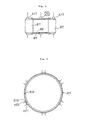
- Fig. 6 is a diagram explanatory of joined portions of the band; and
- Fig. 7 is a side view showing the band conveying device with the band held thereby.
- An embodiment of the present invention will now be described with reference to the drawings.
- In Figs. 1 through 7, A designates a band holding unit, C a traveling carriage, D a base frame, 2 a band, B2, B3, B4 electromagnetic valves, B5, B6 vacuum pressure switches, and A17, A21, A22 vacuum pads.
- In Fig. 1, each band holding unit A is slidably supported via a rectilinear bearing C1 and a rail C2 on the traveling carriage C. The three band holding units are moved on the traveling carriage C by a driving unit of the positionable type (not shown).
- The band holding units A will be described in greater detail with reference to Figs. 1 through 3.
- A frame A1 is secured on the rectilinear bearing C1, a cam A2 is fitted in the frame A1, and pins A3 and A4 are secured to the cam A2. A pin A5 is secured to the cam A2, and a plurality of grooves A6 are formed. A driving unit of the positionable type A8 is pivotably supported via a pin A10 by a bracket A7 attached to the frame A1, and a clevis A9 at the end of a rod A11 of the driving unit A8 is pivotably supported by the pin A5. The frame A1 has a nut A13 attached thereto, and a screw rod A12 is threaded into the nut A13. This screw rod A12 is attached via a bearing (not shown) to the traveling carriage.
- A plurality of levers A14 are pivotably supported by pins A3, and one end A16 of each lever A14 is inserted in the corresponding groove A6 of the cam A2.
- A plurality of levers A15 are pivotably supported by pins A4 secured to the frame A1.
- Fig. 3 shows the band holding unit disposed at either end, in which a vacuum pad A17 is secured to a corresponding block A24, each block A24 has pins A18 and A19 secured thereto, and the corresponding levers A14 and A15 are pivotably supported. The distance between the pins A3 and A19 of the lever A14 is equal to that between the pins A4 and A18 of the lever A15.
- Fig. 2 shows the band holding unit disposed at the center, in which the vacuum pads A21 and A22 are arranged in the circumferential direction and secured to a corresponding block A23 as illustrated, and the pins A18 and A19 are secured to each block A23. The support mechanism of the block A23 is identical with that illustrated in Fig. 3.
- The pipeline network of the vacuum pads A17, A21 and A22 will be described with reference to Fig. 4.
- The vacuum pads A17 of the band holding units disposed at either end are connected together by branch lines extending from one pipeline, and actuated/deactuated by the electromagnetic valve B2. The vacuum pads A21 and A22 of the band holding unit disposed at the center are actuated/ deactuated by the electromagnetic valves B3 and B4, respectively. Vacuum for the electromagnetic valves B3 and B4 is supplied from the output end of the electromagnetic valve B2. The output ends of the electromagnetic valves B3 and B4 are connected to the vacuum pressure switches B5 and B6, respectively.
- The operation of the foregoing units will be described.
- When the band is to be held, first, the electromagnetic valve B2 is turned on to actuate the vacuum pads A17. Then, the electromagnetic valve B3 is turned on. The pressure switch B5 monitors and determines whether or not sufficient vacuum is reached. When sufficient vacuum is reached, the electromagnetic valve B3 is kept on; otherwise, the electromagnetic valve B3 is turned off. Then, the electromagnetic valve B4 is turned on. The pressure switch B6 monitors and determines whether or not sufficient vacuum is reached. When sufficient vacuum is reached, the electromagnetic valve B4 is kept on; otherwise, the electromagnetic valve B4 is turned off.
- A band conveying device according to the present invention, as shown in Fig. 7, holds and conveys the cylindrical band 2 by means of the vacuum pads A17, A21 and A22. As shown in Fig. 5 in greater detail, the band 2 is composed of side walls B7, an inner liner B8, and a ply B9, these being arranged in laminated form. To hold the band, the vacuum pads A17 come into contact with the side walls, and the vacuum pads A21 and A22 come into contact with the ply. Since the side wall as well as the ply is formed by winding a belt-shaped rubber material into a cylindrical shape, they have joined portions arising in a forming step as shown in Fig. 6.
- In Fig. 6, B10 designates a joined portion of the side wall, and B11 designates a joined portion of the ply. Usually, the joined portions arising in the forming step are circumferentially distributed such that they are out of phase or take a phase difference of 90* or 180" therebetween. That is, the joined portions of the side wall and the ply can be distributed so as not to be positionally aligned with the vacuum pads. If such provisions are not incorporated, air leaks through between the vacuum pad and the joined portion (having a rough surface) in contact therewith, resulting in insufficient vacuum.
- Since the side wall B7 is formed by extrusion, its belt-shaped material before a winding step has no joined portion. However, since the ply B9 is formed by connecting a plurality of strip-shaped material segments of given length, its belt-shaped material before the winding step has several joined portions. After the belt-shaped material is wound into a band shape, at least one joined portion (having arisen before the winding step) probably remains on the band. This primary joined portion differs from the joined portion arising in the forming step; thus, it is generally impossible to put the vacuum pad out of alignment with the primary joined portion. Where the holding unit disposed at the center for holding the ply B9 has only one vacuum system of vacuum pads as in the prior art, if the joined portion is aligned with one vacuum pad, the central band-holding unit cannot attain its holding function. Further, if the capacity of a vacuum source is critical, the other vacuum pads cannot get sufficient vacuum, making band conveying impossible.
- According to the present invention, the vacuum pads of the central band-holding unit are circumferentially arranged in paired form and divided into two vacuum systems. Consequently, when the joined portion (arising before the winding step) is aligned with the vacuum pad by any chance, the one vacuum system inclusive of the above vacuum pad is put out of use and the other vacuum system is put in use, whereby the band can be held and conveyed reliably.
- Fig. 6 shows the state wherein a primary joined portion B12 different from the joined portion arising in the forming step is in alignment with the vacuum pad A22. In this case, the electromagnetic valve B4 is turned off, so that the band is held by the vacuum pads A17 and A21.
- In modification, an alarm may be provided which is actuated when both vacuum systems cannot get sufficient vacuum, or an additional pressure switch may be provided in a vacuum system including the vacuum pads A17 to monitor its degree of vacuum.
- As described above, the band conveying device with vacuum attraction mechanism of the present invention comprises; a base frame extending between a band forming station and a tire assembling station, a traveling carriage movable on the base frame, a plurality of band holding units provided on the traveling carriage perpendicularly with respect to the traveling direction thereof, and a plurality of vacuum pads for attracting and holding a band by vacuum which are arranged in annular form and attached to the band holding units; and is characterized in that the vacuum pads are divided into at least two vacuum systems, and each of at least two vacuum systems is provided with a vacuum pressure switch and an electromagnetic valve for shutting off its vacuum system when its degree of vacuum decreases below a given level.
- Therefore, the band can be attracted and conveyed by vacuum even in case where the conventional vacuum system of vacuum pads cannot perform vacuum attraction because of the presence of the joined portion in the band material.
- The joined portion arising in the forming step is properly oriented in the circumferential direction before band conveying, whereby both the joined portion of the band material and the joined portion arising in the forming step can be prevented from being positionally aligned with the vacuum pads.
- The vacuum system whose degree of vacuum has decreased due to the roughness of the joined portion or the like is shut off by the electromagnetic valve responsive to the vacuum pressure switch for detecting the degree of vacuum.
- When the degree of vacuum detected by the vacuum pressure switch is improper, an alarm is raised or the machine is stopped.
Claims (3)
Applications Claiming Priority (2)
| Application Number | Priority Date | Filing Date | Title |
|---|---|---|---|
| JP2263162A JP2691066B2 (en) | 1990-10-02 | 1990-10-02 | Band transfer device using vacuum adsorption |
| JP263162/90 | 1990-10-02 |
Publications (3)
| Publication Number | Publication Date |
|---|---|
| EP0479057A2 true EP0479057A2 (en) | 1992-04-08 |
| EP0479057A3 EP0479057A3 (en) | 1993-02-24 |
| EP0479057B1 EP0479057B1 (en) | 1996-08-07 |
Family
ID=17385644
Family Applications (1)
| Application Number | Title | Priority Date | Filing Date |
|---|---|---|---|
| EP91115950A Expired - Lifetime EP0479057B1 (en) | 1990-10-02 | 1991-09-19 | Band conveying device with vacuum attraction mechanism |
Country Status (6)
| Country | Link |
|---|---|
| US (1) | US5273613A (en) |
| EP (1) | EP0479057B1 (en) |
| JP (1) | JP2691066B2 (en) |
| KR (1) | KR940009916B1 (en) |
| AU (1) | AU627668B2 (en) |
| DE (1) | DE69121229T2 (en) |
Cited By (3)
| Publication number | Priority date | Publication date | Assignee | Title |
|---|---|---|---|---|
| RU2152308C1 (en) * | 1998-12-08 | 2000-07-10 | Закрытое акционерное общество "Поликон" | Device for transfer of pneumatic tyre band blanks |
| RU2226151C2 (en) * | 2002-01-23 | 2004-03-27 | Закрытое акционерное общество "Поликон" | Doffing device for removal of woven canvas auto tires from an assembly drum |
| EP2386406A1 (en) * | 2010-05-12 | 2011-11-16 | Continental Reifen Deutschland GmbH | Method for producing a tyre blank |
Families Citing this family (6)
| Publication number | Priority date | Publication date | Assignee | Title |
|---|---|---|---|---|
| JP2652129B2 (en) * | 1993-07-02 | 1997-09-10 | 住友ゴム工業株式会社 | Transfer for tire molding |
| JPH09201883A (en) * | 1996-01-25 | 1997-08-05 | Bridgestone Corp | Holding mechanism of bead with filler |
| ES2204562T3 (en) | 1999-04-27 | 2004-05-01 | Univeyor A/S | AN APPARATUS FOR HANDLING LAYERS OF PALETIZED ARTICLES. |
| US6736932B2 (en) * | 2001-09-14 | 2004-05-18 | The Goodyear Tire & Rubber Company | Cutting segment for a false drum |
| US6676787B2 (en) * | 2001-09-14 | 2004-01-13 | The Goodyear Tire & Rubber Company | False drum with a variable area vacuum-surface |
| KR100817254B1 (en) * | 2007-03-27 | 2008-03-27 | 한국뉴매틱(주) | Level compensator with built-in vacuum pump |
Family Cites Families (12)
| Publication number | Priority date | Publication date | Assignee | Title |
|---|---|---|---|---|
| US2788411A (en) * | 1955-12-27 | 1957-04-09 | Drying Systems Inc | Control devices |
| US3229953A (en) * | 1964-07-15 | 1966-01-18 | Jr Douglas F Muir | Vacuum workholder and valve means therefor |
| US3484093A (en) * | 1967-07-03 | 1969-12-16 | Sylvania Electric Prod | Article holding apparatus |
| CA942346A (en) * | 1970-03-13 | 1974-02-19 | Federico Capetti | Suction device for picking up sheets |
| US3729206A (en) * | 1971-10-21 | 1973-04-24 | Ibm | Vacuum holding apparatus |
| DE2409586B2 (en) * | 1974-02-28 | 1976-12-09 | Zusatz in: 25 05 486 Continental Gummi-Werke AG, 3000 Hannover | DEVICE FOR TRANSFERRING A CARCASS COVERED WITH CORE RINGS FOR BLANK TIRE TIRES |
| US4473427A (en) * | 1981-06-12 | 1984-09-25 | Mitsubishi Jukogyo Kabushiki Kaisha | Radial tire manufacture apparatus |
| US4634489A (en) * | 1984-07-18 | 1987-01-06 | The Goodyear Tire & Rubber Company | Device for transferring a tire carcass band |
| FR2590019B3 (en) * | 1985-11-14 | 1988-02-12 | Dmsa | DEVICE FOR DETECTING A LOW DEPRESSION IN A PIPELINE |
| JPS6382989A (en) * | 1986-09-11 | 1988-04-13 | 大日本印刷株式会社 | Method of sterilizing or washing cylindrical vessel |
| JPH01255528A (en) * | 1988-04-06 | 1989-10-12 | Mitsubishi Heavy Ind Ltd | Band transfer in tire production device |
| JP2699494B2 (en) * | 1988-12-06 | 1998-01-19 | 松下電器産業株式会社 | Product holding device |
-
1990
- 1990-10-02 JP JP2263162A patent/JP2691066B2/en not_active Expired - Lifetime
-
1991
- 1991-09-19 EP EP91115950A patent/EP0479057B1/en not_active Expired - Lifetime
- 1991-09-19 DE DE69121229T patent/DE69121229T2/en not_active Expired - Fee Related
- 1991-10-01 AU AU85509/91A patent/AU627668B2/en not_active Ceased
- 1991-10-01 US US07/769,639 patent/US5273613A/en not_active Expired - Lifetime
- 1991-10-02 KR KR1019910017256A patent/KR940009916B1/en not_active Expired - Fee Related
Cited By (3)
| Publication number | Priority date | Publication date | Assignee | Title |
|---|---|---|---|---|
| RU2152308C1 (en) * | 1998-12-08 | 2000-07-10 | Закрытое акционерное общество "Поликон" | Device for transfer of pneumatic tyre band blanks |
| RU2226151C2 (en) * | 2002-01-23 | 2004-03-27 | Закрытое акционерное общество "Поликон" | Doffing device for removal of woven canvas auto tires from an assembly drum |
| EP2386406A1 (en) * | 2010-05-12 | 2011-11-16 | Continental Reifen Deutschland GmbH | Method for producing a tyre blank |
Also Published As
| Publication number | Publication date |
|---|---|
| KR920007787A (en) | 1992-05-27 |
| AU8550991A (en) | 1992-04-16 |
| JP2691066B2 (en) | 1997-12-17 |
| EP0479057B1 (en) | 1996-08-07 |
| EP0479057A3 (en) | 1993-02-24 |
| US5273613A (en) | 1993-12-28 |
| DE69121229T2 (en) | 1997-02-06 |
| KR940009916B1 (en) | 1994-10-18 |
| AU627668B2 (en) | 1992-08-27 |
| DE69121229D1 (en) | 1996-09-12 |
| JPH04140130A (en) | 1992-05-14 |
Similar Documents
| Publication | Publication Date | Title |
|---|---|---|
| US5273613A (en) | Band conveying device with vacuum attraction mechanism | |
| US6315104B1 (en) | Accumulation conveyor control system | |
| US20090297316A1 (en) | Integrated Vacuum Gripper with Internal Releasable Magnet and Method of Using Same | |
| JPH04358606A (en) | Roller conveyer | |
| JPH08207251A (en) | Method for automatically supplying plate | |
| JPS59166722A (en) | clutch drive | |
| US20080122640A1 (en) | Method and System for Detecting the Presence of Parts in An Assembly Fixture | |
| US20170339515A1 (en) | Workpiece holding system | |
| US6360866B1 (en) | Conveying apparatus for electric parts | |
| KR102952008B1 (en) | Transfer device for electrode double packaging apparatus and electrode double packaging apparatus comprising the same | |
| JP5603165B2 (en) | Manufacturing apparatus and manufacturing method for annular member | |
| JP3717013B2 (en) | Magnetic bearing device | |
| CN217050384U (en) | Belt conveyor detection device that skids | |
| US20250367970A1 (en) | Wheel Assembly System and Method | |
| JPH0966531A (en) | Stamper holding method and substrate molding method | |
| JP3331613B2 (en) | Nozzle for vacuum differential pressure seal device | |
| JPS6348347Y2 (en) | ||
| US6216934B1 (en) | Festoon protection method and system | |
| JPS6055369A (en) | Form wind-in preventing mechanism of fuser roll | |
| JPH0636035Y2 (en) | Bobbin holder | |
| KR0176508B1 (en) | A control system of a brake-mounted motor | |
| JPH043753Y2 (en) | ||
| WO1996020835A1 (en) | Manifold for print cylinders for mounting expandable sleeves thereon | |
| JP2833226B2 (en) | Paper medium transport device | |
| JPS62140960A (en) | Winding roll supporting device for resin film and the like |
Legal Events
| Date | Code | Title | Description |
|---|---|---|---|
| PUAI | Public reference made under article 153(3) epc to a published international application that has entered the european phase |
Free format text: ORIGINAL CODE: 0009012 |
|
| 17P | Request for examination filed |
Effective date: 19911016 |
|
| AK | Designated contracting states |
Kind code of ref document: A2 Designated state(s): DE NL |
|
| PUAL | Search report despatched |
Free format text: ORIGINAL CODE: 0009013 |
|
| AK | Designated contracting states |
Kind code of ref document: A3 Designated state(s): DE NL |
|
| 17Q | First examination report despatched |
Effective date: 19941208 |
|
| GRAH | Despatch of communication of intention to grant a patent |
Free format text: ORIGINAL CODE: EPIDOS IGRA |
|
| GRAH | Despatch of communication of intention to grant a patent |
Free format text: ORIGINAL CODE: EPIDOS IGRA |
|
| GRAA | (expected) grant |
Free format text: ORIGINAL CODE: 0009210 |
|
| AK | Designated contracting states |
Kind code of ref document: B1 Designated state(s): DE NL |
|
| REF | Corresponds to: |
Ref document number: 69121229 Country of ref document: DE Date of ref document: 19960912 |
|
| PLBE | No opposition filed within time limit |
Free format text: ORIGINAL CODE: 0009261 |
|
| STAA | Information on the status of an ep patent application or granted ep patent |
Free format text: STATUS: NO OPPOSITION FILED WITHIN TIME LIMIT |
|
| 26N | No opposition filed | ||
| PGFP | Annual fee paid to national office [announced via postgrant information from national office to epo] |
Ref country code: DE Payment date: 19980925 Year of fee payment: 8 |
|
| PGFP | Annual fee paid to national office [announced via postgrant information from national office to epo] |
Ref country code: NL Payment date: 19980929 Year of fee payment: 8 |
|
| PG25 | Lapsed in a contracting state [announced via postgrant information from national office to epo] |
Ref country code: NL Free format text: LAPSE BECAUSE OF NON-PAYMENT OF DUE FEES Effective date: 20000401 |
|
| NLV4 | Nl: lapsed or anulled due to non-payment of the annual fee |
Effective date: 20000401 |
|
| PG25 | Lapsed in a contracting state [announced via postgrant information from national office to epo] |
Ref country code: DE Free format text: LAPSE BECAUSE OF NON-PAYMENT OF DUE FEES Effective date: 20000701 |