EP0478894A1 - Microwave antenna arrangement - Google Patents
Microwave antenna arrangement Download PDFInfo
- Publication number
- EP0478894A1 EP0478894A1 EP91109221A EP91109221A EP0478894A1 EP 0478894 A1 EP0478894 A1 EP 0478894A1 EP 91109221 A EP91109221 A EP 91109221A EP 91109221 A EP91109221 A EP 91109221A EP 0478894 A1 EP0478894 A1 EP 0478894A1
- Authority
- EP
- European Patent Office
- Prior art keywords
- joint
- microwave
- antenna arrangement
- flanges
- antenna
- Prior art date
- Legal status (The legal status is an assumption and is not a legal conclusion. Google has not performed a legal analysis and makes no representation as to the accuracy of the status listed.)
- Withdrawn
Links
- 230000005540 biological transmission Effects 0.000 claims description 7
- 230000002093 peripheral effect Effects 0.000 claims description 5
- 239000000428 dust Substances 0.000 claims description 3
- 238000007789 sealing Methods 0.000 description 3
- 238000012986 modification Methods 0.000 description 1
- 230000004048 modification Effects 0.000 description 1
- 230000000717 retained effect Effects 0.000 description 1
Images

Classifications
-
- H—ELECTRICITY
- H01—ELECTRIC ELEMENTS
- H01P—WAVEGUIDES; RESONATORS, LINES, OR OTHER DEVICES OF THE WAVEGUIDE TYPE
- H01P1/00—Auxiliary devices
- H01P1/06—Movable joints, e.g. rotating joints
- H01P1/062—Movable joints, e.g. rotating joints the relative movement being a rotation
- H01P1/066—Movable joints, e.g. rotating joints the relative movement being a rotation with an unlimited angle of rotation
- H01P1/067—Movable joints, e.g. rotating joints the relative movement being a rotation with an unlimited angle of rotation the energy being transmitted in only one line located on the axis of rotation
-
- H—ELECTRICITY
- H01—ELECTRIC ELEMENTS
- H01P—WAVEGUIDES; RESONATORS, LINES, OR OTHER DEVICES OF THE WAVEGUIDE TYPE
- H01P1/00—Auxiliary devices
- H01P1/06—Movable joints, e.g. rotating joints
- H01P1/062—Movable joints, e.g. rotating joints the relative movement being a rotation
- H01P1/063—Movable joints, e.g. rotating joints the relative movement being a rotation with a limited angle of rotation
- H01P1/065—Movable joints, e.g. rotating joints the relative movement being a rotation with a limited angle of rotation the axis of rotation being parallel to the transmission path, e.g. stepped twist
Definitions
- This invention relates to microwave antenna arrangements and more especially it relates to radar antenna arrangements.
- Radar antennas are normally coupled to radar transmitter/receiver apparatus by means of waveguides which are rigid and precisely configured and accordingly such antennas do not lend themselves to rapid deployment from a stored position as may be required for some radar applications.
- the present invention has for an object provide a radar antenna arrangement which may rapidly be deployed from a stowed position.
- a microwave antenna arrangement comprises a first rigid waveguide adapted at one end to communicate for microwave transmission/reception purposes with transmitter/receiver apparatus and at the other end with rotatable joint means, a second rigid waveguide adapted at one end to communicate for microwave transmission/reception purposes with an antenna and at the other end with the rotatable joint means, the joint means comprising at least one joint which is defined by a pair of flanges journaled for relative rotation from a first position whereat the antenna is stowed, to a second position whereat the antenna is deployed, the flanges having juxtaposed joint faces, at least one of which faces has formed therein a choke slot which extends around the joint face of the flange thereby to limit microwave leakage through the joint.
- the choke slot may be annular and may be formed in one flange joint face only.
- the flanges may comprise first and second flanges having apertures formed therein which align in the deployed position to define a microwave transmission path which is matched with the said rigid waveguides, the first flange having a generally circular outer peripheral edge and the second flange having an outer peripheral annular lip, the flanges being journaled between the said edge and the said lip for relative rotation.
- Journal surfaces between the said edge and the said lip may be protected by at least one dust seal.
- the flanges may be journaled for relative rotation by means of a bearing which is supported between the said edge and the said lip.
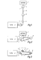
- an antenna arrangement comprises an antenna 1 which is linked to transmitter/receiver apparatus 2 via rigid waveguide sections 3, 4, 5 and 6 which are coupled together by means of rotatable joints 7, 8 and 9.
- Figure 1 the antenna is shown in a deployed position; in Figure 2 the antenna 1 is shown in a stowed position and Figure 3 shows in plan view the antenna of Figures 1 and 2 in the stowed position as in shown in Figure 2.
- angular positional stops are provided on each of the rotatable joints 7, 8 and 9.
- FIG. 4 rectangular waveguide sections 11 and 12 which correspond for example with the waveguide sections 3 and 4 respectively shown in Figure 3, are coupled through a rotatable joint comprising flanges 13 and 14 which are secured to the waveguide sections 11 and 12 respectively.
- a ball race type bearing 15 is secured to an outer circular peripheral edge 16 of the flange 13 the bearing 15 being positioned between the surface 16 of the flange 13 and a lip portion 17 of the flange 14 whereby the flanges 13 and 14 are journaled for relative rotation.
- the bearing 15 is secured in position by means of retaining rings 18 and 19 which are secured by means (not shown) to the flanges 13 and 14 respectively.
- a pair of annular resilient dust sealing rings 20 and 21 which are retained within an annular space 20a defined between the retaining rings 18 and 19.
- a sealing ring 22 is provided on the other side of the bearing 15 in an annular space 22a defined between the flanges 13 and 14.
- annular choke slot 26 is formed in the joint face 24 of the flange 13.
- abutments 27 and 28 are secured to the retaining ring 19 and the lip portion 17 respectively whereby the abutments 27 and 28 serve as angular stops to define a deployed position of the antenna.
- Similar abutments may be provided to define a stowed position such that the antenna may be moved between two fixed positions i.e. a stowed position and a deployed position, the positions being defined by angular stops (not shown) on each of the rotatable joints 7, 8 and 9.
- the waveguide sections 11 and 12 shown in Figure 4 are rectangular and may be bent in the 'E' plane or the 'H' plane in accordance with the particular application in view.
- the antenna 1 and the transmitter receiver apparatus 2 may take any suitable form depending on the use envisaged.
- a radar antenna may be rapidly deployed with precise registration being afforded between the parts of the waveguide which couple the transmitter/receiver apparatus to the antenna.
- apparatus as just before described is eminently suitable for use on portable or transportable radar units.
Landscapes
- Waveguide Connection Structure (AREA)
- Radar Systems Or Details Thereof (AREA)
Abstract
A radar antenna arrangement which lends itself to rapid deployment comprising a plurality of rotatable joints (7-9) between rigid waveguide sections (3-6) linking an antenna with transmitter/receiver apparatus, each joint being rotatable from a stored to a deployed position and embodying a choke slot which serves to prevent microwave leakage.
Description
- This invention relates to microwave antenna arrangements and more especially it relates to radar antenna arrangements.
- Radar antennas are normally coupled to radar transmitter/receiver apparatus by means of waveguides which are rigid and precisely configured and accordingly such antennas do not lend themselves to rapid deployment from a stored position as may be required for some radar applications.
- The present invention has for an object provide a radar antenna arrangement which may rapidly be deployed from a stowed position.
- According to the present invention a microwave antenna arrangement comprises a first rigid waveguide adapted at one end to communicate for microwave transmission/reception purposes with transmitter/receiver apparatus and at the other end with rotatable joint means, a second rigid waveguide adapted at one end to communicate for microwave transmission/reception purposes with an antenna and at the other end with the rotatable joint means, the joint means comprising at least one joint which is defined by a pair of flanges journaled for relative rotation from a first position whereat the antenna is stowed, to a second position whereat the antenna is deployed, the flanges having juxtaposed joint faces, at least one of which faces has formed therein a choke slot which extends around the joint face of the flange thereby to limit microwave leakage through the joint.
- The choke slot may be annular and may be formed in one flange joint face only.
- The flanges may comprise first and second flanges having apertures formed therein which align in the deployed position to define a microwave transmission path which is matched with the said rigid waveguides, the first flange having a generally circular outer peripheral edge and the second flange having an outer peripheral annular lip, the flanges being journaled between the said edge and the said lip for relative rotation.
- Journal surfaces between the said edge and the said lip may be protected by at least one dust seal.
- The flanges may be journaled for relative rotation by means of a bearing which is supported between the said edge and the said lip.
- One embodiment of the invention will now be described solely by way of example with reference to the accompanying drawings in which:
- Figure 1 is a generally schematic side view of an antenna in a deployed position which is linked to transmitter/receiver apparatus through rotatable joints;
- Figure 2 is a generally schematic side view of the antenna of Figure 1 in a stowed position.
- Figure 3 is a generally schematic plan view of the antenna shown in Figure 1 and Figure 2, and
- Figure 4 is an enlarged sectional view of rotatable joints shown in Figure 1, Figure 2 and Figure 3.
- Referring now to Figure 1, an antenna arrangement comprises an antenna 1 which is linked to transmitter/
receiver apparatus 2 viarigid waveguide sections rotatable joints - In Figure 1 the antenna is shown in a deployed position; in Figure 2 the antenna 1 is shown in a stowed position and Figure 3 shows in plan view the antenna of Figures 1 and 2 in the stowed position as in shown in Figure 2. In order precisely to define the deployed position, angular positional stops are provided on each of the
rotatable joints - The rotatable joints will now be described in greater detail with reference to Figure 4. Referring now to Figure 4,
rectangular waveguide sections waveguide sections joint comprising flanges 13 and 14 which are secured to thewaveguide sections peripheral edge 16 of theflange 13 thebearing 15 being positioned between thesurface 16 of theflange 13 and alip portion 17 of the flange 14 whereby theflanges 13 and 14 are journaled for relative rotation. Thebearing 15 is secured in position by means ofretaining rings flanges 13 and 14 respectively. - On one side of the
bearing 15 there are provided a pair of annular resilientdust sealing rings annular space 20a defined between theretaining rings bearing 15 in anannular space 22a defined between theflanges 13 and 14. - In order to prevent the leakage of microwave energy between opposing joint faces 24 and 25 of the
flanges 13 and 14 respectively anannular choke slot 26 is formed in thejoint face 24 of theflange 13. - In order to define stop positions which limit angular relative movement between the
flanges 13 and 14abutments retaining ring 19 and thelip portion 17 respectively whereby theabutments rotatable joints - The
waveguide sections - Various modifications may be made to the arrangement just before described without departing from the scope of the invention and for example other bearing designs may be used comprising flat contact face bearings, or roller bearings and any other suitable bearing sealing arrangement may be employed.
- The antenna 1 and the
transmitter receiver apparatus 2 may take any suitable form depending on the use envisaged. - It will be appreciated that by using a microwave antenna arrangement as hereinbefore described, a radar antenna may be rapidly deployed with precise registration being afforded between the parts of the waveguide which couple the transmitter/receiver apparatus to the antenna. Thus apparatus as just before described is eminently suitable for use on portable or transportable radar units.
Claims (6)
1. A microwave antenna arrangement comprising a first rigid waveguide adapted at one end to communicate for microwave transmission/reception purposes with transmitter/receiver apparatus and at the other end with rotatable joint means, a second rigid waveguide adapted at one end to communicate for microwave transmission/reception purposes with an antenna and at the other end with the rotatable joint means, the said joint means comprising at least one joint defined by a pair of flanges journaled for relative rotation from a first position whereat the antenna is stowed, to a second position whereat the antenna is deployed, the flanges having juxtaposed joint faces, at least one of which faces having formed therein a choke slot which extends around the flange thereby to limit microwave leakage through the joint.
2. A microwave antenna arrangement as claimed in claim 1 wherein the slot is annular and formed in one flange only.
3. A microwave antenna arrangement as claimed in claim 1 or claim 2 wherein the first and second flanges have apertures formed therein which align in the deployed position to define a microwave transmission path which is matched with the rigid waveguides, the first flange having a generally circular outer peripheral edge and the second flange having an outer peripheral annular lip, the flanges being journaled between the said edge and the said lip for relative rotation. A microwave antenna arrangement as claimed in claim 3 wherein the flanges are journaled by means of a bearing positioned between the said edge and the said lip, the said bearing being protected by means of at least one dust seal.
4. A microwave antenna arrangement as claimed in any proceeding claim wherein the joint means comprises a plurality of joints.
5. A microwave antenna arrangement as claimed in any preceding claim wherein the joint means comprises three joints which are coupled by means of rigid waveguide sections thereby to provide a microwave transmission path between transmitter/receiver apparatus and the antenna, each joint being rotatable from the stowed to the deployed position.
6. A microwave antenna arrangement as hereinbefore described with reference to the accompanying drawings.
Applications Claiming Priority (2)
| Application Number | Priority Date | Filing Date | Title |
|---|---|---|---|
| GB9019081 | 1990-09-01 | ||
| GB9019081A GB2247571A (en) | 1990-09-01 | 1990-09-01 | Waveguide joint for a microwave antenna |
Publications (1)
| Publication Number | Publication Date |
|---|---|
| EP0478894A1 true EP0478894A1 (en) | 1992-04-08 |
Family
ID=10681486
Family Applications (1)
| Application Number | Title | Priority Date | Filing Date |
|---|---|---|---|
| EP91109221A Withdrawn EP0478894A1 (en) | 1990-09-01 | 1991-06-06 | Microwave antenna arrangement |
Country Status (4)
| Country | Link |
|---|---|
| EP (1) | EP0478894A1 (en) |
| GB (2) | GB2247571A (en) |
| IL (1) | IL98427A0 (en) |
| NO (1) | NO913404L (en) |
Cited By (2)
| Publication number | Priority date | Publication date | Assignee | Title |
|---|---|---|---|---|
| CN104137326A (en) * | 2012-02-21 | 2014-11-05 | 日本电气株式会社 | Connection structure between antenna device and radio communication device |
| EP3012903A4 (en) * | 2013-06-19 | 2017-03-15 | Japan Aerospace Exploration Agency | System for feeding high-frequency waves to deployment structure |
Citations (5)
| Publication number | Priority date | Publication date | Assignee | Title |
|---|---|---|---|---|
| US2513205A (en) * | 1943-11-19 | 1950-06-27 | Us Navy | Rotatable joint for radio wave guide systems |
| SU1075335A1 (en) * | 1981-06-04 | 1984-02-23 | Предприятие П/Я А-1836 | Wave guide rotary joint |
| GB2127369A (en) * | 1982-09-03 | 1984-04-11 | Marconi Avionics | Retractable radar scanner for aircraft |
| FR2619469A1 (en) * | 1987-08-14 | 1989-02-17 | Spinner Georg | JUNCTION ELEMENT FOR WAVEGUIDES WITH TILT AND / OR ROTATION LENGTH COMPENSATION |
| FR2632456A1 (en) * | 1982-10-15 | 1989-12-08 | Dassault Electronique | Rotating joints for EHF waveguide systems - has two cup sections with air gap forming resonant chamber plus peripheral ball bearing for support |
Family Cites Families (4)
| Publication number | Priority date | Publication date | Assignee | Title |
|---|---|---|---|---|
| FR1067518A (en) * | 1951-12-12 | 1954-06-16 | Bendix Aviat Corp | Wide band rotary joint for waveguide |
| GB1565971A (en) * | 1977-01-10 | 1980-04-23 | Marconi Co Ltd | Waveguide joints |
| GB2096405B (en) * | 1981-03-27 | 1984-10-24 | Marconi Co Ltd | A waveguide joint |
| US4701731A (en) * | 1986-04-23 | 1987-10-20 | Hughes Aircraft Company | Pivotable conical joint for waveguides |
-
1990
- 1990-09-01 GB GB9019081A patent/GB2247571A/en not_active Withdrawn
-
1991
- 1991-06-06 EP EP91109221A patent/EP0478894A1/en not_active Withdrawn
- 1991-06-10 IL IL98427A patent/IL98427A0/en unknown
- 1991-06-13 GB GB9112782A patent/GB2247572A/en not_active Withdrawn
- 1991-08-30 NO NO91913404A patent/NO913404L/en unknown
Patent Citations (5)
| Publication number | Priority date | Publication date | Assignee | Title |
|---|---|---|---|---|
| US2513205A (en) * | 1943-11-19 | 1950-06-27 | Us Navy | Rotatable joint for radio wave guide systems |
| SU1075335A1 (en) * | 1981-06-04 | 1984-02-23 | Предприятие П/Я А-1836 | Wave guide rotary joint |
| GB2127369A (en) * | 1982-09-03 | 1984-04-11 | Marconi Avionics | Retractable radar scanner for aircraft |
| FR2632456A1 (en) * | 1982-10-15 | 1989-12-08 | Dassault Electronique | Rotating joints for EHF waveguide systems - has two cup sections with air gap forming resonant chamber plus peripheral ball bearing for support |
| FR2619469A1 (en) * | 1987-08-14 | 1989-02-17 | Spinner Georg | JUNCTION ELEMENT FOR WAVEGUIDES WITH TILT AND / OR ROTATION LENGTH COMPENSATION |
Non-Patent Citations (1)
| Title |
|---|
| SOVIET INVENTIONS ILLUSTRATED Section Electrical, week 8442, abstract no. 262323, W02, 26 November 1984; & SU - A - 1075335 (KISELEV) 23.02.1984 * |
Cited By (6)
| Publication number | Priority date | Publication date | Assignee | Title |
|---|---|---|---|---|
| CN104137326A (en) * | 2012-02-21 | 2014-11-05 | 日本电气株式会社 | Connection structure between antenna device and radio communication device |
| EP2819238A4 (en) * | 2012-02-21 | 2015-11-04 | Nec Corp | Connection structure for antenna apparatus and wireless communications apparatus |
| RU2581739C2 (en) * | 2012-02-21 | 2016-04-20 | Нек Корпорейшн | Connection structure between antenna device and radio communication device |
| US9653769B2 (en) | 2012-02-21 | 2017-05-16 | Nec Corporation | Connection structure between antenna apparatus and radio communication apparatus |
| EP3012903A4 (en) * | 2013-06-19 | 2017-03-15 | Japan Aerospace Exploration Agency | System for feeding high-frequency waves to deployment structure |
| US10290913B2 (en) | 2013-06-19 | 2019-05-14 | Japan Aerospace Exploration Agency | Deployment structure comprised of flat panels with waveguides disposed therein, where the flat panels are rotated into engagement with each other to couple the waveguides |
Also Published As
| Publication number | Publication date |
|---|---|
| GB9019081D0 (en) | 1991-07-10 |
| GB2247571A (en) | 1992-03-04 |
| GB9112782D0 (en) | 1991-08-07 |
| NO913404D0 (en) | 1991-08-30 |
| GB2247572A (en) | 1992-03-04 |
| IL98427A0 (en) | 1992-07-15 |
| NO913404L (en) | 1992-03-02 |
Similar Documents
| Publication | Publication Date | Title |
|---|---|---|
| US5157393A (en) | Communication system for transmitting data between a transmitting antenna utilizing leaky coaxial cable and a receive antenna in relative movement to one another | |
| EP1008777A3 (en) | Tripod type constant velocity universal joint | |
| US6749516B2 (en) | Constant velocity joint and mechanical transmission member for same | |
| AU4755893A (en) | Sectorized cellular radio base station antenna | |
| AU2117595A (en) | Sectorized multi-function cellular radio communication system | |
| US9653769B2 (en) | Connection structure between antenna apparatus and radio communication apparatus | |
| US6375576B1 (en) | Mechanical transmission member and its application to a mechanical constant velocity joint | |
| CA2292207A1 (en) | Constant velocity universal joint and method for assembling the same | |
| US20170200997A1 (en) | Waveguide hinge | |
| NL8400008A (en) | ARRANGEMENT FOR A ROUND SEARCH. | |
| WO1994026001A1 (en) | Steerable antenna systems | |
| FR2442520B1 (en) | ||
| GB2247571A (en) | Waveguide joint for a microwave antenna | |
| US10741897B2 (en) | RF rotary joint using a matched horn coupler assembly | |
| IT1118595B (en) | GROUP OF HUB AND AUTOMATIC JOINT FOR WHEELS OF VEHICLES | |
| US10433808B2 (en) | Rotary joint having a capacitive data link with modular support | |
| US4036032A (en) | Universal joint | |
| US4664303A (en) | Simplified mount for a web-supporting roller | |
| DK0640260T3 (en) | Mobile radio network with central information on the cells | |
| US7476156B2 (en) | Homokinetic joint | |
| US6593898B2 (en) | Antenna apparatus in mobile communication system | |
| JPS622802Y2 (en) | ||
| EP1108911A3 (en) | Flexible coupling, especially multilayer joint coupling | |
| JPS57138230A (en) | Optical slip ring | |
| US2867101A (en) | Universal joint |
Legal Events
| Date | Code | Title | Description |
|---|---|---|---|
| PUAI | Public reference made under article 153(3) epc to a published international application that has entered the european phase |
Free format text: ORIGINAL CODE: 0009012 |
|
| AK | Designated contracting states |
Kind code of ref document: A1 Designated state(s): DE FR IT NL SE |
|
| STAA | Information on the status of an ep patent application or granted ep patent |
Free format text: STATUS: THE APPLICATION HAS BEEN WITHDRAWN |
|
| 18W | Application withdrawn |
Withdrawal date: 19920430 |