EP0478361A1 - Method of assembling a plurality of printed circuit boards - Google Patents
Method of assembling a plurality of printed circuit boards Download PDFInfo
- Publication number
- EP0478361A1 EP0478361A1 EP91308848A EP91308848A EP0478361A1 EP 0478361 A1 EP0478361 A1 EP 0478361A1 EP 91308848 A EP91308848 A EP 91308848A EP 91308848 A EP91308848 A EP 91308848A EP 0478361 A1 EP0478361 A1 EP 0478361A1
- Authority
- EP
- European Patent Office
- Prior art keywords
- board
- machine
- boards
- component
- components
- Prior art date
- Legal status (The legal status is an assumption and is not a legal conclusion. Google has not performed a legal analysis and makes no representation as to the accuracy of the status listed.)
- Granted
Links
Images


Classifications
-
- G—PHYSICS
- G06—COMPUTING; CALCULATING OR COUNTING
- G06Q—INFORMATION AND COMMUNICATION TECHNOLOGY [ICT] SPECIALLY ADAPTED FOR ADMINISTRATIVE, COMMERCIAL, FINANCIAL, MANAGERIAL OR SUPERVISORY PURPOSES; SYSTEMS OR METHODS SPECIALLY ADAPTED FOR ADMINISTRATIVE, COMMERCIAL, FINANCIAL, MANAGERIAL OR SUPERVISORY PURPOSES, NOT OTHERWISE PROVIDED FOR
- G06Q10/00—Administration; Management
- G06Q10/04—Forecasting or optimisation specially adapted for administrative or management purposes, e.g. linear programming or "cutting stock problem"
-
- H—ELECTRICITY
- H05—ELECTRIC TECHNIQUES NOT OTHERWISE PROVIDED FOR
- H05K—PRINTED CIRCUITS; CASINGS OR CONSTRUCTIONAL DETAILS OF ELECTRIC APPARATUS; MANUFACTURE OF ASSEMBLAGES OF ELECTRICAL COMPONENTS
- H05K13/00—Apparatus or processes specially adapted for manufacturing or adjusting assemblages of electric components
- H05K13/08—Monitoring manufacture of assemblages
- H05K13/085—Production planning, e.g. of allocation of products to machines, of mounting sequences at machine or facility level
-
- Y—GENERAL TAGGING OF NEW TECHNOLOGICAL DEVELOPMENTS; GENERAL TAGGING OF CROSS-SECTIONAL TECHNOLOGIES SPANNING OVER SEVERAL SECTIONS OF THE IPC; TECHNICAL SUBJECTS COVERED BY FORMER USPC CROSS-REFERENCE ART COLLECTIONS [XRACs] AND DIGESTS
- Y02—TECHNOLOGIES OR APPLICATIONS FOR MITIGATION OR ADAPTATION AGAINST CLIMATE CHANGE
- Y02P—CLIMATE CHANGE MITIGATION TECHNOLOGIES IN THE PRODUCTION OR PROCESSING OF GOODS
- Y02P90/00—Enabling technologies with a potential contribution to greenhouse gas [GHG] emissions mitigation
- Y02P90/02—Total factory control, e.g. smart factories, flexible manufacturing systems [FMS] or integrated manufacturing systems [IMS]
Definitions
- This invention relates generally to work allocation in an assembly line, and more specifically to operation assignment problems in a printed circuit (PC) board assembly process.
- PC printed circuit
- FMS Flexible Manufacturing Systems
- That problem is to allocate operations and required tools among groups of machines, while meeting technological and capacity constrains of the machines.
- the prior art suggested a number of different objectives, including balancing machine workloads and minimising the number of movements of jobs between machines.
- One prior formulation of the FMS tool loading problem is an assignment problem with a linear objective -- that of assigning job types to machines in order to minimise total variable processing cost per job, subject to machine capacity constraints.
- the assignment problem of the present invention includes not only variable processing cost per operation, but also a one time setup cost per job if any operations of a given job are carried out on a particular machine. This setup cost is incurred because of the particular technology we are considering, as described below.
- the FMS tool loading problem is a tactical problem that is concerned with objectives such as maximising throughput or minimising makespan, given a known set of jobs to be processed.
- Our assignment problem is a longer term planning problem that has the objective of minimising expected production cost (or, equivalently, minimising the average expected cost per unit produced) given estimates of expected future demand.
- PC printed circuit
- An object of the invention is to provide a system and method for optimising operation assignments in printed circuit board manufacturing involving components which can either be inserted on board manually or by machine.
- a related object is to determine an optimum assignment of components ("operations") to a set of capacited machines to minimise the total setup and processing cost for assembling all boards, with the possibility of certain remaining components being inserted manually.
- Another object is to focus on an operation assignment problem to determine an assignment of operations to a set of capacited machines to minimise total setup and processing costs. Since these costs may be expressed in terms of time units required for setup and processing, a related object is to minimise the average time required to produce each PC board.
- the invention provides two different solution methods which individually can in certain circumstances be arbitrarily bad, but which on the average produce satisfactory results. In the case of multiple machine, the invention provides four different solution methods.
- a method of determining the assignment of operations to one or more machines having a given capacity for installing multiple parts to items in an assembly line comprising: preparing a list of parts of each different item being assembled; determining the production demand for each different item; and applying an algorithm based on said parts list and said production demand to minimise total setup and processing cost.
- one manual insertion process works as follows: the board is set up on a tray, the operator locates the assembly instructions for this particular board in an instruction manual, and then follows the assembly instruction, obtaining individual components from labeled bins that are located in the assembly area, and inserting them manually onto the board.
- the board is set up on a tray on a semi-automated component insertion machine, and the operator enters the board identification number into the computer that controls the machine. Then the machine identifies from a set of internal component bins the bin containing the first part that is needed, opens the bin , and moves it on the board where this component is to be inserted.
- a one-time tooling of machines i.e., assignment of components to bins
- a one-time tooling of machines i.e., assignment of components to bins
- the next year or half year is determined based on annual or semi-annual expected (high estimates of) demand for different types of boards.
- new demand estimates are generated, and the machines may be retooled.
- Fig. 1 shows an actual cumulative component usage as a percentage of total usage for a sample of 30 boards assembled from over 300 components.
- Fig. 2 shows an actual distribution of the number of different boards that components are used in for a representative sample of 58 boards and 180 components. In this instance, approximately 35% of the components are used in more than one board, and 5% of the components are used in 5 or more boards. This low commonality of components occurs in part because of the long product lives of many of these products which use the PC boards.
- the problem we consider is that of determining which components (operations) to assign to each process (this may be any of the machines, or the manual assembly process) in order to minimize total setup and processing cost for assembling all boards. If components for any particular board are not all assigned to the same process (i.e., the same machine, or the manual assembly process), then the board must undergo more than one setup. (We assume, however, that the order of component insertion does not matter, so that at most one setup per process will be required for any one board.) In order to avoid multiple setups, it is possible to assign the same component to different processes. Thus, the problem is also one of determining the layout of the different machines -- that is, determining the extent to which assembly should be performed on parallel vs. serial processes. Note that we are solving a long term planning problem using estimates of expected future demand for the next 6 to 12 months, so batching and sequencing are not issues of concern.
- the objective is to form an operating policy (i.e., to determine flows of board types among machines) that provides a basis for tactical execution.
- Weekly planning may involve subcontracting out work in periods of high demand, and operator training classes in periods of low demand.
- one capacity and people have been positioned (we assumed that this has already taken place), they represent a largely fixed cost, so a design is needed that allows for efficient tactical execution.
- the objective of minimizing average expected cost per board produced reflects actual manufacturing planning and is appropriate for a long term planning problem of the type we are considering. Because we are solving a long term planning problem (using extimated future demand), it is sensible to consider minimizing the average cost per board produced, rather than measures such as makespan minimization and throughput maximization that may be applicable to a problem with a shorter horizon and known demand requirements. Note that costs may be expressed in terms of the time units required for each operation: in this case, because there may be parallel machines operating simultaneously, the objective is not equivalent to minimizing makespan but, rather, is equivalent to minimizing the average time required to process a board. (We assume that all boards can be processed in the available time; otherwise the problem does not have a feasible solution.)
- N i total number of types of components that can be assigned to process i
- the objective (1) is to minimize total processing plus setup cost.
- Constraint (2) ensures that all necessary components will be assigned to a process; if any component for board k is assigned to a process, (3) sets the indicator variable y ik to 1 so that a setup will be charged.
- Constraints (4) and (5) express the upper limit on the number of different types of components that can be assigned to any process.
- N I J, and so is not included in (5).
- bounding by solving a relaxed linear program (dropping the integrality constraint on the y ik 's).
- An efficient way to carry out the branching process may be to branch first on the most frequently used components (that is, those with the highest value of since those components will have the greatest effect on total cost.
- a good initial upper bound can be obtained using the heuristics presented in Sections 3 and 4.
- Step 1 assigns all components to the machine.
- the component which adds the minimum incremental cost is removed, and the objective function, setup indicators ( ⁇ k ), and costs are updated.
- the removal process continues until the bin capacity of the machine is exactly met.
- Step 2 we observe that each time Step 2 is reached, at most J sums are calculated, and one sort is performed, leading to a maximum of J2log(J) calculations each time. Step 2 is reaches J-N l times, so an upper limit on the computational complexity for the Stingy Component algorithm is J3log(J) steps.
- Step 1 assigns all boards to the manual process.
- Step 2 the incremental number of new component slots per board produced ( ⁇ k ) is calculated for each board whose incremental assignment to the machine will not violate the slot capacity constraint (represented by k ⁇ T), and the board with the minimum value is assigned to the machine. (This is equivalent to "greedily” maximizing incremental boards produced per additional slot used.) The process continues until no more (entire) boards can be assigned to the machine.
- Step 3 the post-processing step, is similar to that for the Stingy Component heuristic (in this case, for boards which incur a manual setup (i.e., k ⁇ T), a decision is made as to whether or not to process some of the components on the machine).
- Step 2 For the Greedy Board algorithm, each time Step 2 is reached, at most K sums and one sort over K are performed, leading to K2log(K) computations. Step 2 is reached at most K times, so an upper limit on the computation required is K3log(K) steps. Since K ⁇ J, and in a typical problem K ⁇ J, the Greedy Board algorithm will typically require less computation than the Stingy Component algorithm.
- the Greedy Board algorithm when there is no component commonality across boards, and the Greedy Board algorithm can exactly fill the component slots on the machine, then the algorithm will always yield the optimal solution.
- the algorithm is akin to the High Ratio First algorithm for the 0-1 knapsack problem -- a greedy heuristic which sequentially adds items to the knapsack based on their value-to-weight ratio; that heuristic provides an optimal solution when the knapsack can be exactly filled.
- the Greedy Board algorithm might also expect the Greedy Board algorithm to perform well when processing costs on the two processes are similar, because in that case no cost savings can be achieved by splitting boards.
- the Stingy Component heuristic can generate an arbitrarily poor solution.
- the Greedy Board heuristic can generate an arbitrarily poor solution, even when it uses all slots on the machine.
- the first N1 boards each use one component, 1,...,N1.
- the remaining boards each use one of the first N1 components, plus two or more of components N1+1,...2N1. All such possible combinations are included; so, for example, the number of different boards using two of the components N1+1,...,2N1 (plus one of components 1,...,N1) is
- the Greedy Board heuristic uses all slots on the machine (as does the optimal solution). For this example, Clearly, as N1 gets large, R ⁇ 1.
- the second version of our Multiple Machine Stingy Component algorithm differs only in that, after applying the Single Machine Stingy Component algorithm, we remove from consideration only those components associated only with boards that can be completely processed on machine i:
- the second version is:
- Results are shown in Table 2.
- the Greedy Board algorithms were superior to the Stingy Component algorithms, with Version 2 of the Greedy algorithm yielding the best solutions.
- the average deviation from J min for the Stingy Component solutions was 7-10%, while the average deviation from J min for the Greedy Board algorithm was 3-5%.
- the Greedy Board approach was used.
- the Greedy Board approach was preferred by process engineers because boards assembled completely using one process tend to have higher quality and lower rework requirement than do boards produced using more than one process.
- the first application involved component assignment in a division that manufactures test and measurement equipment.
- the division had been manually assembling a mix of almost 500 boards from several thousand components.
- the division had purchased six new semi-automatic component insertion machines, each of which had slots for 640 components, and wanted to shift some of the production to the machines.
- This problem was solved using Version 2 of the Multiple Machine Greedy Board Algorithm.
- the results of the algorithm was a partition of the boards into families that could be processed together on the same machine. After applying the algorithm to determine board families, one for each of the six machines, and the remainder for the manual process, a subsequent step was taken to reassign some of the boards among the machines in order to balance the workloads of the different machines. This reassignment, performed using the procedure described was carried out because each of the 6 machines was manned by a different operator. The manufacturing process was then set up to reflect these board families.
- the second application involved the manufacture of PC boards for computers in another division.
- a wide mix of boards is assembled on a surface mount technology (SMT) line that consists of a set of pick-and-place component insertion machines.
- SMT surface mount technology
- any components needed for the second board that are not on the machines when the first board is completed must be set up on the machines before the second board can be produced.
- no additional setups are required when two boards of the same type are produced sequentially.
- the problem was to determine a production plan for the boards that would minimize production cost.
- Two different solution approaches were considered. The first approach was to apply real-time sequencing of boards in order to minimize the setup time between boards; this approach minimizes the number of new components that must be set up on a machine before the next board can be produced.
- the second approach was to apply Version 2 of the Multiple Machine Greedy Board Algorithm to group the boards into families that could be produced with no setup between boards; in this case, the number of machine slots considered by the algorithm equals the total number of machine slots in the SMT line. Step 2 of the algorithm was repeated until all boards were grouped into families.
- the idea with the Greedy Board solution is to set up once for a single board family, produce all boards in that family, and then set up for the next board family, etc. Once the boards were grouped into families, workloads associated with different board groups were balanced using the procedure outlined. Board were switched between groups until the production volumes of different groups were balanced appropriately.
- the invention provides two different heuristic solution approaches, one of which focuses on assigning components while the other focuses on assigning boards. Both algorithms yield good solutions for problems similar to those described above, but given cost data for certain actual assembly processes, the Greedy Board algorithms provided slightly better solutions in the experimental applications. This reflects the fact that the Stingy Component algorighms will tend to provide better solutions when the setup costs are low. The Greedy Board algorithms appear to provide better solutions when setup costs are high. The Greedy Board approach was found to have the additional advantage of providing a solution in which most boards are assigned to only one process: this leads to higher quality and lower rework requirements than an assignment that splits boards across processes.
Landscapes
- Engineering & Computer Science (AREA)
- Business, Economics & Management (AREA)
- Human Resources & Organizations (AREA)
- Operations Research (AREA)
- Economics (AREA)
- Strategic Management (AREA)
- Manufacturing & Machinery (AREA)
- Microelectronics & Electronic Packaging (AREA)
- Entrepreneurship & Innovation (AREA)
- Game Theory and Decision Science (AREA)
- Development Economics (AREA)
- Marketing (AREA)
- Quality & Reliability (AREA)
- Tourism & Hospitality (AREA)
- Physics & Mathematics (AREA)
- General Business, Economics & Management (AREA)
- General Physics & Mathematics (AREA)
- Theoretical Computer Science (AREA)
- General Factory Administration (AREA)
- Supply And Installment Of Electrical Components (AREA)
- Management, Administration, Business Operations System, And Electronic Commerce (AREA)
Abstract
Description
- This application relates to copending application --------- claiming priority from U.S. Serial no: 07/584,748 with inventors Thomas C. Davis and Eva M. Selep, entitled "High Mix Printed Circuit Assembly Technique", which is incorporated herein by reference.
- This invention relates generally to work allocation in an assembly line, and more specifically to operation assignment problems in a printed circuit (PC) board assembly process.
- Along with the advent of powerful automated manufacturing systems has come a host of complex design and control problems. These problems include machine grouping, part type selection, operation assignment, fixture allocation, and tool loading. Some of these problems have already been considered in the prior art, such as the tool loading problem of Flexible Manufacturing Systems (FMS's). That problem is to allocate operations and required tools among groups of machines, while meeting technological and capacity constrains of the machines. The prior art suggested a number of different objectives, including balancing machine workloads and minimising the number of movements of jobs between machines. One prior formulation of the FMS tool loading problem is an assignment problem with a linear objective -- that of assigning job types to machines in order to minimise total variable processing cost per job, subject to machine capacity constraints.
- Other prior formulations of the FMS tool loading problem consider the variable cost associated with each operation. In contrast, the assignment problem of the present invention includes not only variable processing cost per operation, but also a one time setup cost per job if any operations of a given job are carried out on a particular machine. This setup cost is incurred because of the particular technology we are considering, as described below. In addition, the FMS tool loading problem is a tactical problem that is concerned with objectives such as maximising throughput or minimising makespan, given a known set of jobs to be processed. Our assignment problem is a longer term planning problem that has the objective of minimising expected production cost (or, equivalently, minimising the average expected cost per unit produced) given estimates of expected future demand.
- The problem solved by the present invention arose from conventional printed circuit (PC) board assembly operations wherein a unit assembles a number of different PC boards by inserting the appropriate components. The process is not fully automated because a wide mix of boards is produced, and the volume of production does not justify automation. Component insertion in this hand load cell can either be performed manually or by a semi-automated machine. Prior techniques did not adequately solve the assembly problems in this type of PCV board manufacturing line.
- An object of the invention is to provide a system and method for optimising operation assignments in printed circuit board manufacturing involving components which can either be inserted on board manually or by machine. A related object is to determine an optimum assignment of components ("operations") to a set of capacited machines to minimise the total setup and processing cost for assembling all boards, with the possibility of certain remaining components being inserted manually.
- Another object is to focus on an operation assignment problem to determine an assignment of operations to a set of capacited machines to minimise total setup and processing costs. Since these costs may be expressed in terms of time units required for setup and processing, a related object is to minimise the average time required to produce each PC board.
- Even though the problem can be formulated as a mixed integer linear program, it is too large to be practically solved. Accordingly, in the case of a single machine the invention provides two different solution methods which individually can in certain circumstances be arbitrarily bad, but which on the average produce satisfactory results. In the case of multiple machine, the invention provides four different solution methods.
- According to the present invention there is provided a method of determining the assignment of operations to one or more machines having a given capacity for installing multiple parts to items in an assembly line comprising:
preparing a list of parts of each different item being assembled;
determining the production demand for each different item; and
applying an algorithm based on said parts list and said production demand to minimise total setup and processing cost. - Preferred embodiments of the present invention will now be described, by way of example only, with reference to the accompanying drawings, of which
- Fig. 1 is a graphical representation of actual data for an exemplary PC board assembly line;
- Fig. 2 is a different graphical representation of the exemplary PC board assembly line of Fig. 1 showing parts commonality between boards;
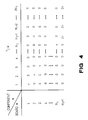
- Fig. 3 shows an application of the Greedy Board algorithm to an exemplary combination of components and boards; the number of slots available is 4, the greedy board solution is:
Boards
Total cost - 3s₁ + 4s₂ + 18c
and the optimal solution is:
Boards
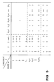
Total cost - 4s₁ + 3s₂ + 18c - Fig. 4 shows an application of the Stingy Component algorithm to another exemplary combination of components and boards; it illustrates the worst case example for the stingy component heuristic; the stingy component solution is:
Board N₁ + 1 on machine;
all others on manual;
Cost - v[2s₁ + 2N₁c₁ + N₁s₂ + N1c2]
the optimal solution is:
Boards 1,...., N₁ on machine;
Board N₁ + 1 on manual;
Cost - v[N₁s₁ + N₁c₁ + 2s₂ + 2N₁c₂] - Fig. 5 shows an application of the Greedy Board algorithm to a further combination of components and boards; it illustrates the worst case for the greedy board heuristic;

- Fig. 6 is a high level flow chart of the invention;
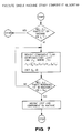
- Fig. 7 is a flow chart showing the Stingy Component algorithm applied to a single machine assembly; one starts with the minimum cost solution (all on machine) and keeps removing components in a stingy fashion;
- Fig. 8 is a flow chart showing the Greedy Board algorithm applied to a single machine assembly; one starts with the most expensive solution (all by hand) and greedily moves the board (sets of components) to machine; and
- Fig. 9 is a flow chart showing the Stingy Component algorithm applied to a multiple machine assembly.
4. The method of any preceding claim, wherein said method is used with multiple machines on an assembly line. - There are many conventional PC board assembly operations which can be optimized by the present invention. For example, one manual insertion process works as follows: the board is set up on a tray, the operator locates the assembly instructions for this particular board in an instruction manual, and then follows the assembly instruction, obtaining individual components from labeled bins that are located in the assembly area, and inserting them manually onto the board. For the semi-automatic insertion process, the board is set up on a tray on a semi-automated component insertion machine, and the operator enters the board identification number into the computer that controls the machine. Then the machine identifies from a set of internal component bins the bin containing the first part that is needed, opens the bin , and moves it on the board where this component is to be inserted. The operator removes a component from the open bin, inserts it manually onto the board, and presses a switch indicating that another component is now needed. The machine then closes and removes the bin, pulls up the bin containing the next component that is required, and the process continues similarly until all components have been inserted. Note that there are no setup savings associated with producing two of the same type of boards sequentially; each board requires setup on any process where it undergoes component insertion. This is an example of a through-hole assembly process.
- Both setup and processing are faster (i.e., cheaper) on a machine. However, the machines have a limited capacity for holding different components, and only a limited number of the machines are available. Furthermore, it is costly to change the assignment of components to bins of the machine: such changes involve not only physical replacement of components in the bins inside the machine, but also reprogramming the machine's computer. In addition, costly reductions in board quality and yield may occur when the production process is changed (e.g., when a particular board is now assembled using a different machine). Thus, component assignment must be performed before any PC boards can be assembled, and cannot be changed during the entire assembly process of all boards. It is not possible to change the set of components on the machine until all the boards have been completely assembled. In a typical situation, a one-time tooling of machines (i.e., assignment of components to bins) for the next year or half year is determined based on annual or semi-annual expected (high estimates of) demand for different types of boards. At the end of that time period, new demand estimates are generated, and the machines may be retooled.
- As is typical in PC board assembly operations, a large number of different PC boards, assembled from an even larger number of components, must be produced. For example, in one typical manufacturing process, almost 500 types of PC boards are produced from some 4000 different parts. Another feature of interest is that some components are used much more frequently than others. Fig. 1 shows an actual cumulative component usage as a percentage of total usage for a sample of 30 boards assembled from over 300 components.
- Finally, there is a low but not insignificant level of component commonality between boards. Fig. 2 shows an actual distribution of the number of different boards that components are used in for a representative sample of 58 boards and 180 components. In this instance, approximately 35% of the components are used in more than one board, and 5% of the components are used in 5 or more boards. This low commonality of components occurs in part because of the long product lives of many of these products which use the PC boards.
- The problem we consider is that of determining which components (operations) to assign to each process (this may be any of the machines, or the manual assembly process) in order to minimize total setup and processing cost for assembling all boards. If components for any particular board are not all assigned to the same process (i.e., the same machine, or the manual assembly process), then the board must undergo more than one setup. (We assume, however, that the order of component insertion does not matter, so that at most one setup per process will be required for any one board.) In order to avoid multiple setups, it is possible to assign the same component to different processes. Thus, the problem is also one of determining the layout of the different machines -- that is, determining the extent to which assembly should be performed on parallel vs. serial processes. Note that we are solving a long term planning problem using estimates of expected future demand for the next 6 to 12 months, so batching and sequencing are not issues of concern.
- In effect, the objective is to form an operating policy (i.e., to determine flows of board types among machines) that provides a basis for tactical execution. Weekly planning may involve subcontracting out work in periods of high demand, and operator training classes in periods of low demand. In any case, one capacity and people have been positioned (we assumed that this has already taken place), they represent a largely fixed cost, so a design is needed that allows for efficient tactical execution.
- The objective of minimizing average expected cost per board produced reflects actual manufacturing planning and is appropriate for a long term planning problem of the type we are considering. Because we are solving a long term planning problem (using extimated future demand), it is sensible to consider minimizing the average cost per board produced, rather than measures such as makespan minimization and throughput maximization that may be applicable to a problem with a shorter horizon and known demand requirements. Note that costs may be expressed in terms of the time units required for each operation: in this case, because there may be parallel machines operating simultaneously, the objective is not equivalent to minimizing makespan but, rather, is equivalent to minimizing the average time required to process a board. (We assume that all boards can be processed in the available time; otherwise the problem does not have a feasible solution.)
- In our model, operation assignments are determined using fixed estimates of future demand. A natural extension is to consider incertainties in these demand estimates. In this case one would like to create assignment plans that are robust with respect to possible future changes in demand. Such assignment plans would yield low cost under a range of assumptions about levels of future demand for different products.
- In the following section we formally define the problem as a mixed integer program. We discuss approaches for finding an exact solution. In many practical applications, however, a realistic problem may be too large to solve exactly. Furthermore, in a preferred embodiment, process engineers wanted a solution methodology that could be implemented on a desktop computer rather than a mainframe computer. Thus we develop solution heuristics for the problem. Initially we specialize our analysis to the case of one machine. We present two different solution heuristics. We characterize conditions under which the algorithms generate an optimal solution, present worst case examples, and present computational results for a randomly generated set of problems. We show that while each algorithm can be arbitrarily bad, for typical problems the algorithms perform well. Thereafter, we consider the more general case of multiple machines. We develop four different solution heuristics, and present computational experience. Finally, we will discuss implementation of our results on an actual assembly line.
- We let i be an index for processes (1,2,3,...,I-1 = machine; I = manual), j be an index for components (j = 1,...,J), and k be an index for boards (k = 1,...,K). Our goal is to determine optimal values for:
xijk = assignment of component j of board k to process i,
where xijk = 1 if the assignment is made; 0 otherwise - We also define the following dummy variables:
yik = 1 if board k set up for any insertions on process i; 0 otherwise
zij = 1 if component j is assigned to process i; 0 otherwise - Production requirements are:
dk = total demand for board k over the (fixed) time period
rjk = 1 if component j is used in board k; 0 otherwise
njk = number of component j used in one of board type k - Using these, we define:
vjk = dkrjknjk = total volume of component j used for boards of type k over the time period - Setup and processing costs, by machine, are the same over all boards and components:
si = setup cost for one setup of one board on process i
ci = processing cost for one insertion by process i - Finally, machine limitations are given by:
Ni = total number of types of components that can be assigned to process i - Given these definitions, the problem can be expressed as:
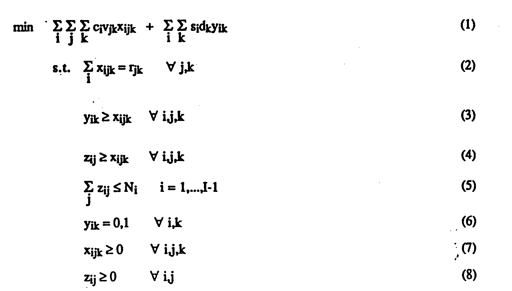
The objective (1) is to minimize total processing plus setup cost. Constraint (2) ensures that all necessary components will be assigned to a process; if any component for board k is assigned to a process, (3) sets the indicator variable yik to 1 so that a setup will be charged. Constraints (4) and (5) express the upper limit on the number of different types of components that can be assigned to any process. The manual process is assumed to have NI = J, and so is not included in (5). We note that, given (6), an integrality constraint on the xijk's is not necessary; the above mixed ILP will always yield xijk = 0 or 1 for all i,j,k. Similarly, we do not need to specify an integrality constraint for the zij's (which are dummy variables): If all bins of process i are used in the cost-minimizing solution, then the zij's will all be binary integer-valued for that process. If all bins are not used, the optimal solution is degenerate and the zij's may not be binary interger-valued; however, this will not affect the optimal solution (specified by the yik's and xijk's). The problem is thus one of I·K binary integer variables and I·J·(K+1) linear variables. - We note that the above formulation allows for the assignment of a single component type to more than one process. (The only constraint on assignment of components to processes (the zij's) is that the number of different component types assigned to any one process cannot exceed the capacity of the process). When setup times are high relative to processing costs (so that it is costly to produce a board using more than one process), and all boards that use a particular high volume component cannot be fully assembled on any one machine because their combined requirement for component types is larger than the number of component slots available, then it may be optimal to assign the component to more than one process.
- One solution approach for this problem is to use branch and bound, branching on component assignments (i.e., set zij = 0 or 1), and bounding by solving a relaxed linear program (dropping the integrality constraint on the yik's). An efficient way to carry out the branching process may be to branch first on the most frequently used components (that is, those with the highest value of

since those components will have the greatest effect on total cost. We do not need to explicitly specify whether or not a component is assigned to the manual process: since the manual process is assumed to be uncapacitated, components will automatically be assigned to that process by the linear program if necessary or desirable. A good initial upper bound can be obtained using the heuristics presented inSections - The difficulty with solving the integer program exactly for a realistic problem is the large problem size. For example, a medium sized 2-process assignment problem (with one machine, plus the manual process) might involve 200 boards and 6000 components--leading to 12,000 binary integer variables and over 2 millions linear variables. Even with no integer restrictions, such a problem is too large to solve using current LP codes. Furthermore, in our experimental applications process engineers wanted a solution methodology that could be implemented on a desktop computer rather than a mainframe computer. Thus, we now develop heuristic ways of solving the problem. We first consider the case of one machine, and then the case of multiple machines.
- In this section, we specialize our discussion to the case of one machine. We let i = 1 represent the machine and i = 2 the manual process. The problem then reduces to one of determining which components to assign to the machine (zlj): Once the machine bins have been filled, all unassigned components are assigned to the manual process. In addition, some components assigned to the machine may also be assigned to the manual process. Given the component assignments, the cost minimizing solution for each board (the xijk's and corresponding yik's) can be determined individually.
- Although a realistically sized problem is too large to be practically solved by an exact solution method, certain special characteristics of the problem enable us to construct excellent near-optimal solution approaches. First, some components are used much more frequently than other and some boards are assembled much more frequently than others (data in Figure 1 verify that both component and board usages follow the well-known "80/20" rule). Since both setup and insertion are cheaper on a machine than on the manual process, we would expect that the optimal solution would assign many (or all) of the frequently used components and/or boards to a machine. We also observe that, excluding certain frequently used components, boards do not tend to have much component commonality. This motivates us to construct two different solution heuristics based on a "greedy" approach, one of which assigns individual components, and one which assigns entire boards.
- Our first solution approach, which we refer to as the "Stingy Component" algorithm, starts by assigning all components to the machine (thus exceeding the machine's capacity constraint) and then sequentially removing components which cause the smallest cost increase, until the machine's capacity constraint is met. All components not assigned to the machine are assigned to the manual process. In addition, some components may be assigned to both processses if a lower cost can be achieved.
- The idea behind this approach is that many of the less frequently used components will never be assigned to the machine in a cost-minimizing solution and, similarly, one would expect the most frequently used components to always be assigned to the machine. Since the "stingy" approach focuses on assigning individual components rather than entire boards, we would expect the algorithm to perform well when setup costs are low. In fact, when setup costs are zero, the stingy algorithm always generates the optimal problem solution, since in that case each component can be considered individually.
- We let i = 1 represent the machine and i = 2 the manual process. Then we have:
-
- 1. Initialization: Let S = {1,...,J}. Let δk = 1 for all k, and

- 2. "Stingy" Component Removal:
Calculate

- 3. Post-Processing: If ISI > N₁, return to
Step 2. Otherwise,- (i) For all j ∉ S: set x2jk = rjk, x1jk = 0, for all k.
- (ii) For all k s.t. δk = 1: set y1k = 1, y2k = 0, and x2jk = 0, x1jk = rjk for all j.
- (iii) For all k s.t. δk = 0: set y2k = 1, and
if

-
Step 1 assigns all components to the machine. InStep 2, the incremental cost of removing each component from the machine (Δj) is calculated; this consists of the incremental variable processing cost per unit (c₂-c₁) times the total affected volume
plus the incremental manual setup cost for any boards using that component which have not yet incurred a manual setup cost (i.e., those boards for which δk = 1 at this step.) The component which adds the minimum incremental cost is removed, and the objective function, setup indicators (δk), and costs are updated.The removal process continues until the bin capacity of the machine is exactly met.Step 3 is a post-processing step that sets the decision variables. All boards which incur no manual setup (δk = 1) are processed completely by the machine. For those boards that do incur a manual setup (δk = 0), a decision is made about whether or not to process the board entirely on the manual process; if it is cheaper to do so, the decision variables are adjusted and the objective function is updated. - We observe that each
time Step 2 is reached, at most J sums are calculated, and one sort is performed, leading to a maximum of J²log(J) calculations each time.Step 2 is reaches J-Nl times, so an upper limit on the computational complexity for the Stingy Component algorithm is J³log(J) steps. - Our second solution approach, which we refer to as the "Greedy Board" algorithm, starts by assigning all boards to the manual process, and then assigns entire boards to the machine, one by one, to maximize incremental boards produced per incremental component bin used. In contrast to the Stingy Component algorithm, the Greedy Board algorithm focuses on entire boards. The ideas motivating this approach are that: (a) because of the expected low level of component commonality, it may be better to assign boards entirely to the machines or the manual process, rather than splitting them; and (b) consideration of existing component commonality may yield cost saving combinations of boards assigned to the machine.
- The algorithm can be formally stated as follows:
-
- 1. Initialization: Let S = φ, T = {1,...,K}, and

- 2. "Greedy" Board Loading: Calculate

where

- 3. Post-Processing: If T ≠ φ, return to
Step 2. Otherwise,- (i) For all j ∉ S: set x2jk = rjk, xljk = 0, for all k.
- (ii) For all k ∉ T: set y1k = 1, y2k = 0, and x2jk = 0, x1jk = rjk for all j.
- (iii) For all k ε T: set y2k = 1, and
if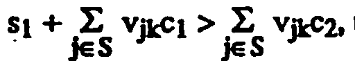

-
Step 1 assigns all boards to the manual process. InStep 2, the incremental number of new component slots per board produced (γk) is calculated for each board whose incremental assignment to the machine will not violate the slot capacity constraint (represented by k ε T), and the board with the minimum value is assigned to the machine. (This is equivalent to "greedily" maximizing incremental boards produced per additional slot used.) The process continues until no more (entire) boards can be assigned to the machine.Step 3, the post-processing step, is similar to that for the Stingy Component heuristic (in this case, for boards which incur a manual setup (i.e., k ε T), a decision is made as to whether or not to process some of the components on the machine). - For the Greedy Board algorithm, each
time Step 2 is reached, at most K sums and one sort over K are performed, leading to K²log(K) computations.Step 2 is reached at most K times, so an upper limit on the computation required is K³log(K) steps. Since K ≦ J, and in a typical problem K << J, the Greedy Board algorithm will typically require less computation than the Stingy Component algorithm. - We observe that when there is no component commonality across boards, and the Greedy Board algorithm can exactly fill the component slots on the machine, then the algorithm will always yield the optimal solution. In this case, the algorithm is akin to the High Ratio First algorithm for the 0-1 knapsack problem -- a greedy heuristic which sequentially adds items to the knapsack based on their value-to-weight ratio; that heuristic provides an optimal solution when the knapsack can be exactly filled. We might also expect the Greedy Board algorithm to perform well when processing costs on the two processes are similar, because in that case no cost savings can be achieved by splitting boards. However, even if the manual and machine processing costs are identical, and the Greedy Board algorithm uses all machine slots, the algorithm may not yield the optimal solution, since the algorithm takes into account component commonality only myopically. The optimal solution under these conditions is one which maximizes the volume of boards assigned to the machine. The Greedy Board algorithm will not necessarily yield that solution. An example is shown in Figure 3.
- We now investigate the performance of the two solution algorithms. We show that while the worst case performance of each heuristic can be arbitrarily bad, on average each performed quite well over a large sample of randomly generated problems.
- Because our problem is one of minimization, we use the worst case performance ratio R = [JH - J*]/[Jmax - J*]; here, JH represents the cost of the heuristic solution, J* the optimal solution, and Jmax an upper bound on the maximum objective function value. The closer the ratio is to 1, the worse the performance of the heuristic. For an upper bound we use

this corresponds to assembling all boards on the manual process. - The Stingy Component heuristic can generate an arbitrarily poor solution.
- Consider the example shown in Figure 4. For the Stingy Component heuristic, JH = v[2s₁ + 2N₁c₁ + N₁s₂ + N₁c₂] while J* = v[N₁s₁ + N₁c₁ + 2s₂ + 2N₁c₂]. The upper bound is Jmax = v[(N₁ + 2)s₂ + (3N₁)c₂]. Thus,

As N₁ becomes sufficiently large, this expression approaches
- We can similarly show by example that the Greedy Board heuristic can produce arbitrarily poor solutions.
- The Greedy Board heuristic can generate an arbitrarily poor solution, even when it uses all slots on the machine.
- Consider the example shown in Figure 5. There are 2N₁ components. The first N₁ boards each use one component, 1,...,N₁. The remaining boards each use one of the first N₁ components, plus two or more of components N₁+1,...2N₁. All such possible combinations are included; so, for example, the number of different boards using two of the components N₁+1,...,2N₁ (plus one of
components 1,...,N₁) is
The Greedy Board heuristic uses all slots on the machine (as does the optimal solution). For this example,
Clearly, as N₁ gets large, R → 1. - In order to assess average performance, the two algorithms were tested on a set of problem instances that were randomly generated from observed distributions of board volume and component frequency and commonality in the assembly process. The setup and processing costs used reflect relative actual costs, and are proportional to the time required for each operation. For each problem, the true optimal solution was determined by exhaustive search. Computational results are shown in Table 1. For problems of
size 10 × 15 (10 boards and 15
components), the Stingy heuristic was slightly better than the Greedy heuristic, with an average error of about 3.1%, as compared to 4.2% for the Greedy heuristic. For problems ofsize 10 × 20, the Greedy heuristic performed better, with an average error of 4.2% versus 4.8% for the Stingy heuristic. Interestingly, while the average error increased slightly for the large sized problems, the maximum error for each heuristic decreased significantly. - Since the two heuristics focus on different aspects of the problem (the Stingy heuristic focuses on individual component volume, while the Greedy heuristic focuses on component commonality between boards), a compound heuristic using the minimum of the two solutions was created;
the average performance of the compound heuristic was significantly better than either algorithm alone. - We now consider the original multiple machine problem. We assume that the machines are identical, so that si = si+1, ci = ci+1, Ni = Ni+1, i = 1,..., I-1; this is the case in our applications
- Our solutions approach for the multiple machine case is to apply our single machine heuristics to each machine sequentially; then, as before, once we have made an initial assignment of components to machines, we carry out a post-processing step to determine if some boards can be made more cheaply by reassigning them. For each of the single machine heuristics (Stingy Component and Greedy Board), we develop two different multiple machine heuristics. These heuristics differ in the extent to which we allow part assignment to more than one machine: In the first case, if component j is assigned to machine i, then when we assign components to machine i+1 we no longer consider component j; while in the second case, we do consider potential assignment of component j to machine i+1. Our two adaptations of the Stingy algorithm for the case of multiple machines are as follows:
-
- 1. Initialization: Let i = 1. Let SK = {1,...,K}, SJ = {1,...,J}.
- 2. "Stingy" Component Assignment: Apply the Stingy Component Algorithm to machine i, considering the board set SK and component set SJ.
- 2. Updating: Remove from SK those boards that are completely processed on machine i, and remove from set SJ those components assigned to machine i. Let i = i+1. If i<I, return to
Step 2. - 3. Post-Processing: Given the assignment of components to machines: for each board not completely processed on a single machine, determine the least cost way to produce the board (i.e., on a combination of machines vs. machine and manual vs. manual only).
Stop. - The second version of our Multiple Machine Stingy Component algorithm differs only in that, after applying the Single Machine Stingy Component algorithm, we remove from consideration only those components associated only with boards that can be completely processed on machine i:
-
- 1. Initialization: Let i = 1. Let SK = {1,...,K}, SJ = {1,...,J}.
- 2. "Stingy" Component Assignment: Apply the Stingy Component Algorithm to machine i, considering the board set SK and component set SJ.
- 2. Updating: Remove from SK those boards that are completely processed on machine i, and remove from set SJ those components that are associated only with boards that can be completely processed on machine i. Let i = i+1. If i<I, return to
Step 2. - 3. Post-Processing: Given the assignment of components to machines: for each board not completely processed on a single machine, determine the least cost way to produce the board (i.e., on a combination of machines vs. machine and manual vs. manual only).
Stop. - Analogously, we develop two versions of a Multiple Machine Greedy Board algorithm:
-
- 1. Initialization: Let i = 1. Let SK = {1,...,K}, SJ = {1,...,J}.
- 2. "Greedy" Board Assignment: Apply the Greedy Board Algorithm to machine i, considering the board set SK and component set SJ.
- 2. Updating: Remove from SK those boards that are completely processed on machine i, and remove from set SJ those components assigned to machine i. Let i = i+1. If i<I, return to
Step 2. - 3. Post-Processing: Given the assignment of components to machines: for each board not completely processed on a single machine, determine the least cost way to produce the board (i.e., on a combination of machines vs. machine and manual vs. manual only).
Stop. - The second version is:
-
- 1. Initialization: Let i = 1. Let SK = {1,...,K}, SJ = {1,...,J}.
- 2. "Greedy" Board Assignment: Apply the Greedy Board Algorithm to machine i, considering the board set SK and component set SJ.
- 2. Updating: Remove from SK those boards that are completely processed on machine i, and remove from set SJ those components that are associated only with boards that can be completely processed on machine i. Let i = i+1. If i<I, return to
Step 2. - 3. Post-Processing: Given the assignment of components to machines: for each board not completely processed on a single machine, determine the least cost way to produce the board (i.e., on a combination of machines vs. machine and manual vs. manual only).
Stop. - These algorithms were tested on a set of 30 two-machine problem instances that were randomly generated from observed distributions of board volume and component frequency and commonality in the assembly process. The setup and processing costs used reflect relative actual costs and are proportional to the time required for each operation. The problem instances each involved 20 boards and 100 components, with 35 component slots available on each of the two machines. Because of the large problem size (100 components), it was not possible to determine the true optimal solution for each problem, so instead we used as a lower bound the cost of producing each board on a single machine:

- Results are shown in Table 2. For all 30 problems, the Greedy Board algorithms were superior to the Stingy Component algorithms, with
Version 2 of the Greedy algorithm yielding the best solutions. The average deviation from Jmin for the Stingy Component solutions was 7-10%, while the average deviation from Jmin for the Greedy Board algorithm was 3-5%. These percentage differences are encouragingly small, considering the fact that the measured deviation is based on comparison to an infeasible lower bound. - We note that each of our multiple machine heuristics applies the individual stingy or greedy heuristic to each machine; thus, the computational complexity of the Multiple Machine Stingy Component algorithms is I·J³log(J), while the computational complexity of the Multiple Machine Greedy Board algorithms is I·K³log(K). These differences are reflected in the running time of the algorithms. For the two-machine examples of Table 2, running time using a PASCAL program on a Macintosh IIc/x was an average of 27 seconds for the Stingy Component algorithms, and an average of 3 seconds for the Greedy Board algorithms.
- Thus far we have made no mention of workload balancing. It is possible that the above solution algorithms may generate solutions in which some machines are assigned a much larger volume of production than other machines. We deal with issue of workload balancing in the following manner: When we execute the solution algorithm, we set the number of available slots on each machine to a number slightly smaller than the actual number of slots available. (In our example applications, we used a number that was approximately 97% of the actual slot capacity.) Then, on an ad hoc basis, we consider potential reassignment of boards among the processes. We fill the unused slots with certain frequently used components to enable us to make the reassignment. This procedure was quite effective in our following experimental applications.

- Our algorithms were applied to two different PC board manufacturing problems.
- In both applications, the Greedy Board approach was used. One reason this approach was favored over the Stingy Component approach was that setup costs were high relative to insertion costs, and the Greedy Board approaches tend to yield fewer setups for each board. In addition, the Greedy Board approach was preferred by process engineers because boards assembled completely using one process tend to have higher quality and lower rework requirement than do boards produced using more than one process.
- The first application involved component assignment in a division that manufactures test and measurement equipment. The division had been manually assembling a mix of almost 500 boards from several thousand components. The division had purchased six new semi-automatic component insertion machines, each of which had slots for 640 components, and wanted to shift some of the production to the machines. This problem was solved using
Version 2 of the Multiple Machine Greedy Board Algorithm. The results of the algorithm was a partition of the boards into families that could be processed together on the same machine. After applying the algorithm to determine board families, one for each of the six machines, and the remainder for the manual process, a subsequent step was taken to reassign some of the boards among the machines in order to balance the workloads of the different machines. This reassignment, performed using the procedure described was carried out because each of the 6 machines was manned by a different operator. The manufacturing process was then set up to reflect these board families. - The second application involved the manufacture of PC boards for computers in another division. In this operation, a wide mix of boards is assembled on a surface mount technology (SMT) line that consists of a set of pick-and-place component insertion machines. In producing two sequential boards, any components needed for the second board that are not on the machines when the first board is completed, must be set up on the machines before the second board can be produced. However, no additional setups are required when two boards of the same type are produced sequentially. The problem was to determine a production plan for the boards that would minimize production cost. Two different solution approaches were considered. The first approach was to apply real-time sequencing of boards in order to minimize the setup time between boards; this approach minimizes the number of new components that must be set up on a machine before the next board can be produced. The second approach was to apply
Version 2 of the Multiple Machine Greedy Board Algorithm to group the boards into families that could be produced with no setup between boards; in this case, the number of machine slots considered by the algorithm equals the total number of machine slots in the SMT line.Step 2 of the algorithm was repeated until all boards were grouped into families. The idea with the Greedy Board solution is to set up once for a single board family, produce all boards in that family, and then set up for the next board family, etc. Once the boards were grouped into families, workloads associated with different board groups were balanced using the procedure outlined. Board were switched between groups until the production volumes of different groups were balanced appropriately. - Both the setup minimizing and Greedy Board solutions were evaluated using a computer simulation. While the setup minimization approach yielded a solution with 2% more throughput than the Greedy Board approach, the setup minimizing solution incurred long cycle times for boards, since the real-time setup minimization algorithm can indefinitely postpone assembly of some boards if they incur too much setup time. The Greedy Board solution had the advantage of shorter cycle times. In addition, the manufacturing process is much simpler to manage when boards are grouped into families, since only one setup must be performed for each family of boards. For these reasons, the Greedy Board solution was chosen and implemented.
- In view of all the foregoing, it will be understood by those skilled in the art that the invention provides two different heuristic solution approaches, one of which focuses on assigning components while the other focuses on assigning boards. Both algorithms yield good solutions for problems similar to those described above, but given cost data for certain actual assembly processes, the Greedy Board algorithms provided slightly better solutions in the experimental applications. This reflects the fact that the Stingy Component algorighms will tend to provide better solutions when the setup costs are low. The Greedy Board algorithms appear to provide better solutions when setup costs are high. The Greedy Board approach was found to have the additional advantage of providing a solution in which most boards are assigned to only one process: this leads to higher quality and lower rework requirements than an assignment that splits boards across processes.
- We have discussed experimental implementation of our results for two different production processes. The first application -- component assignment for PC board assembly in a test and measurement -- was the original problem that gave rise to our model and solution approaches. The second application -- creating board families for PC board production in a computer manufacturing operation -- shows the link between our solution approaches and group technology concepts. Our approach is believed to have an advantage over traditional group technology approaches since we consider not only commonality of components between different products, but also product and component volume.
- As formulated, our model considers the setup cost associated with different assembly processes, but does not consider the transportation time or cost required to move a board between different processes. In our particular applications, transportation cost was not significant because machine capacities were quite large relative to component requirements of individual boards; thus, it rarely happened that a board was split among more than two processes when the problem was solved. In some applications, however, consideration of transportation cost between processes may be important. A simple way to extend the model (and our solution heuristics) to incorporate transportation times is to assume a fixed transportation cost (t) between any two processes and add a transportation cost equal to (-1 +Σiyik)t to the objective function (1). Then in the Stingy Component algorithm, when we add incremental setup cost (Step 2), we also add transportation cost. We do not need to add transportation cost when making initial assignments using the Greedy Board algorithm (
Steps 1 and 2) since no boards are split between processes. Then, during the post-processing step (Step 3) transportation cost can be added in both algorithms. - Our Greedy Board and Stingy Component algorithms are designed to take advantage of the date structure typically found in PC board assembly processes: our algorithms exploit certain characteristics of PC board demand and component requirements, such as component commonality and wide variations in component usage and board demands. We showed that, for typical PC board and component demand data, the algorithms yields solutions that are very close to optimal.
Claims (7)
- A method of determining the assignment of operations to one or more machines having a given capacity for installing multiple parts to items in an assembly line comprising:
preparing a list of parts of each different item being assembled;
determining the production demand for each different item; and
applying an algorithm based on said parts list and said
production demand to minimize total setup and processing cost. - The method of claim 1 wherein said applying step includes starting with a minimum cost solution for a machine having unlimited parts installation capacity and then selectively removing parts so as to minimize processing cost until the number of parts is within the actual machine capacity.
- The method of claim 1 wherein said applying step includes starting with a maximum cost solution of all items having parts installed without using the machine, and then selectively moving installation to the machine based on part to volume ratio.
- The method of any preceding claim, wherein said method is used with multiple machines on an assembly line.
- The method of any preceding claim, wherein said method is used on an assembly line for installing components on a printed circuit board.
- The method of claim 5 wherein said applying step includes developing an assembly model based on applying a stingy component algorithm, and also developing another assembly model based on applying a greedy board algorithm, and then implementing the lower cost solution of the two on the assembly line.
- A manufacturing plant set up to operate in accordance with a method according to any preceding claim.
Applications Claiming Priority (2)
| Application Number | Priority Date | Filing Date | Title |
|---|---|---|---|
| US07/590,611 US5258915A (en) | 1990-09-28 | 1990-09-28 | System and method for optimum operation assignments in printed circuit board manufacturing |
| US590611 | 2000-06-09 |
Publications (2)
| Publication Number | Publication Date |
|---|---|
| EP0478361A1 true EP0478361A1 (en) | 1992-04-01 |
| EP0478361B1 EP0478361B1 (en) | 1996-11-13 |
Family
ID=24362930
Family Applications (1)
| Application Number | Title | Priority Date | Filing Date |
|---|---|---|---|
| EP91308848A Expired - Lifetime EP0478361B1 (en) | 1990-09-28 | 1991-09-27 | Method of assembling a plurality of printed circuit boards |
Country Status (6)
| Country | Link |
|---|---|
| US (1) | US5258915A (en) |
| EP (1) | EP0478361B1 (en) |
| JP (1) | JPH04257968A (en) |
| KR (1) | KR920007514A (en) |
| DE (1) | DE69123120T2 (en) |
| HK (1) | HK32897A (en) |
Cited By (9)
| Publication number | Priority date | Publication date | Assignee | Title |
|---|---|---|---|---|
| WO2004114036A1 (en) * | 2003-06-20 | 2004-12-29 | Matsushita Electric Industrial Co., Ltd. | Information processing device and production device |
| WO2014005743A1 (en) * | 2012-07-06 | 2014-01-09 | Siemens Aktiengesellschaft | Allocation of printed circuit boards to fitting lines |
| WO2014005744A1 (en) * | 2012-07-06 | 2014-01-09 | Siemens Aktiengesellschaft | Allocation of printed circuit boards on fitting lines |
| WO2014005742A1 (en) * | 2012-07-06 | 2014-01-09 | Siemens Aktiengesellschaft | Formation of equipment families on fitting lines |
| WO2014005741A1 (en) * | 2012-07-06 | 2014-01-09 | Siemens Aktiengesellschaft | Allocation of printed circuit boards on fitting lines |
| WO2016074857A1 (en) * | 2014-11-11 | 2016-05-19 | Siemens Aktiengesellschaft | Population of printed circuit boards |
| CN109934427A (en) * | 2017-12-15 | 2019-06-25 | 北京京东尚科信息技术有限公司 | The method and apparatus for generating article allocation plan |
| WO2022022811A1 (en) * | 2020-07-28 | 2022-02-03 | Siemens Aktiengesellschaft | Method and device for populating circuit boards by means of fixedly assigned components on at least two assembly lines |
| WO2022022810A1 (en) * | 2020-07-28 | 2022-02-03 | Siemens Aktiengesellschaft | Method and device for populating circuit boards by means of fixedly assigned components on an assembly line |
Families Citing this family (29)
| Publication number | Priority date | Publication date | Assignee | Title |
|---|---|---|---|---|
| US5325305A (en) * | 1992-07-24 | 1994-06-28 | The Boeing Company | Automated setup verification system |
| US5523960A (en) * | 1994-08-10 | 1996-06-04 | Samsung Electronics Co., Ltd. | Evaluation method of assembly sequences |
| JPH09282374A (en) * | 1996-04-16 | 1997-10-31 | Matsushita Electric Ind Co Ltd | Mounting factory management support system |
| JP3537267B2 (en) * | 1996-06-06 | 2004-06-14 | 松下電器産業株式会社 | Equipment operation method |
| US6378200B1 (en) | 1997-09-18 | 2002-04-30 | Motorola, Inc. | Dynamically reconfigurable assembly line for electronic products |
| WO1998049646A2 (en) * | 1997-05-01 | 1998-11-05 | Motorola Inc. | Dynamically reconfigurable assembly line for electronic products |
| JP2003030250A (en) * | 2001-07-12 | 2003-01-31 | Oki Electric Ind Co Ltd | System for estimating printed board design man-hour and estimation program |
| US7027885B1 (en) * | 2002-12-30 | 2006-04-11 | Advanced Micro Devices, Inc. | Determining batch start versus delay |
| US6829514B2 (en) * | 2003-01-17 | 2004-12-07 | Motorola, Inc. | Balancing workloads in an electronics assembly factory |
| TWI276932B (en) * | 2005-02-17 | 2007-03-21 | Powerchip Semiconductor Corp | Methods for determining tool assignment sequence and manufacturing systems using the same |
| EP1777648A1 (en) * | 2005-10-24 | 2007-04-25 | Sap Ag | Production planning with sequence independent setup activities |
| US9008836B2 (en) * | 2007-01-09 | 2015-04-14 | Abb Inc. | Method and system for robotic assembly parameter optimization |
| DE102009013353B3 (en) * | 2009-03-16 | 2010-10-07 | Siemens Aktiengesellschaft | Method for determining armor for constant tables of placement machines |
| DE102009039988A1 (en) * | 2009-09-03 | 2011-03-17 | Siemens Aktiengesellschaft | Travels for painting robots |
| KR102032367B1 (en) * | 2012-10-05 | 2019-10-16 | 한국전자통신연구원 | Apparatus and method for processing task |
| CN103838219A (en) * | 2013-09-09 | 2014-06-04 | 昆明理工大学 | Optimized dispatching method of photosensitive resistance welding process in multilayer printed circuit board manufacturing |
| DE102014222936A1 (en) * | 2014-11-11 | 2016-05-12 | Siemens Aktiengesellschaft | Assembly of printed circuit boards |
| CN104571007B (en) * | 2014-11-20 | 2018-11-27 | 昆明理工大学 | The Optimization Scheduling of general assembly line production assembling process in a kind of automotive manufacture |
| DE102014225713A1 (en) * | 2014-12-12 | 2016-06-16 | Siemens Aktiengesellschaft | Method and system for assembling printed circuit boards and computer program product for carrying out the method |
| DE102015200420A1 (en) * | 2015-01-14 | 2016-07-14 | Siemens Aktiengesellschaft | Method and system for assembling printed circuit boards |
| EP3383159B1 (en) * | 2015-03-26 | 2021-02-17 | FUJI Corporation | Optimization device for component mounting line and optimization method for component mounting line |
| CN108781530B (en) | 2016-03-10 | 2020-07-10 | 西门子股份公司 | Method and device for distributing components to assembly lines |
| CN108781531B (en) * | 2016-03-10 | 2020-07-10 | 西门子股份公司 | Method and device for distributing components to assembly lines |
| JP6635191B2 (en) * | 2016-04-26 | 2020-01-22 | 富士通株式会社 | Manufacturing plan generating apparatus, manufacturing plan generating method, and manufacturing plan generating program |
| CN109074055B (en) * | 2016-04-26 | 2021-06-15 | 富士通株式会社 | Work support device, work support method, and computer-readable storage medium storing work support program |
| JP6837198B2 (en) * | 2016-11-30 | 2021-03-03 | パナソニックIpマネジメント株式会社 | Equipment configuration creation support system and equipment configuration creation support method |
| EP3474650B1 (en) * | 2017-10-19 | 2020-12-09 | Sick Ag | Method for producing a retrofitting set for an assembly machine |
| CN109063932B (en) * | 2018-09-10 | 2021-07-16 | 昆明理工大学 | Optimized scheduling method for electric cabinet assembly process |
| JP6609893B2 (en) * | 2018-12-04 | 2019-11-27 | 株式会社Fuji | Component mounter, board production line, and component type allocation method |
Citations (1)
| Publication number | Priority date | Publication date | Assignee | Title |
|---|---|---|---|---|
| EP0164563A1 (en) * | 1984-05-16 | 1985-12-18 | Siemens Aktiengesellschaft | Method of making flat component assemblies |
Family Cites Families (7)
| Publication number | Priority date | Publication date | Assignee | Title |
|---|---|---|---|---|
| US4646238A (en) * | 1984-10-26 | 1987-02-24 | Analog Devices, Inc. | Material requirements planning system and procedures for use in process industries |
| JPH0668696B2 (en) * | 1985-02-22 | 1994-08-31 | 株式会社日立製作所 | NC data creation method for inserter |
| US4648023A (en) * | 1985-05-23 | 1987-03-03 | Powell Roger A | Method for resource allocation for the manufacture of a product |
| US4885686A (en) * | 1987-01-12 | 1989-12-05 | American Telephone And Telegraph At&T Bell Laboratories | Methods and apparatus for efficient resource allocation |
| US4887207A (en) * | 1987-12-29 | 1989-12-12 | International Business Machines Corporation | Automated system for evaluating the sensitivity of inventory costs due to fluctuations in customer demand |
| US5077661A (en) * | 1989-05-03 | 1991-12-31 | Hewlett-Packard Company | Assignment-dependent resource allocation method |
| US5170554A (en) * | 1990-09-28 | 1992-12-15 | Hewlett-Packard Company | High mix printed circuit assembly technique |
-
1990
- 1990-09-28 US US07/590,611 patent/US5258915A/en not_active Expired - Fee Related
-
1991
- 1991-09-27 EP EP91308848A patent/EP0478361B1/en not_active Expired - Lifetime
- 1991-09-27 KR KR1019910016917A patent/KR920007514A/en not_active Application Discontinuation
- 1991-09-27 DE DE69123120T patent/DE69123120T2/en not_active Expired - Fee Related
- 1991-09-30 JP JP3251648A patent/JPH04257968A/en active Pending
-
1997
- 1997-03-20 HK HK32897A patent/HK32897A/en not_active IP Right Cessation
Patent Citations (1)
| Publication number | Priority date | Publication date | Assignee | Title |
|---|---|---|---|---|
| EP0164563A1 (en) * | 1984-05-16 | 1985-12-18 | Siemens Aktiengesellschaft | Method of making flat component assemblies |
Non-Patent Citations (2)
| Title |
|---|
| * the whole document * * |
| AT & T TECHNICAL JOURNAL vol. 68, no. 3, June 1989, NEW YORK US pages 93 - 102; ARVIND RAJAN: 'ASSIGNING COMPONENTS TO ROBOTIC WORCELLS FOR ELECTRONIC ASSEMBLY' * |
Cited By (21)
| Publication number | Priority date | Publication date | Assignee | Title |
|---|---|---|---|---|
| WO2004114036A1 (en) * | 2003-06-20 | 2004-12-29 | Matsushita Electric Industrial Co., Ltd. | Information processing device and production device |
| CN100424604C (en) * | 2003-06-20 | 2008-10-08 | 松下电器产业株式会社 | Information processing device and production device |
| CN104396362B (en) * | 2012-07-06 | 2017-11-03 | 西门子公司 | Circuit board is assigned on assembly line |
| US9888620B2 (en) | 2012-07-06 | 2018-02-06 | Siemens Aktiengesellschaft | Allocation of printed circuit boards on fitting lines |
| WO2014005742A1 (en) * | 2012-07-06 | 2014-01-09 | Siemens Aktiengesellschaft | Formation of equipment families on fitting lines |
| WO2014005741A1 (en) * | 2012-07-06 | 2014-01-09 | Siemens Aktiengesellschaft | Allocation of printed circuit boards on fitting lines |
| CN104396362A (en) * | 2012-07-06 | 2015-03-04 | 西门子公司 | Allocation of printed circuit boards to fitting lines |
| CN104412284A (en) * | 2012-07-06 | 2015-03-11 | 西门子公司 | Formation of equipment families on fitting lines |
| CN104412284B (en) * | 2012-07-06 | 2019-01-01 | 西门子公司 | With the method and control device of electronic component assembly printed circuit board on assembly line |
| CN104412733B (en) * | 2012-07-06 | 2016-11-09 | 西门子公司 | Wiring harness plate is with the method and apparatus to circuit board assembling electronic component |
| WO2014005743A1 (en) * | 2012-07-06 | 2014-01-09 | Siemens Aktiengesellschaft | Allocation of printed circuit boards to fitting lines |
| WO2014005744A1 (en) * | 2012-07-06 | 2014-01-09 | Siemens Aktiengesellschaft | Allocation of printed circuit boards on fitting lines |
| US9955620B2 (en) | 2012-07-06 | 2018-04-24 | Siemens Aktiengesellschaft | Formation of equipment families on fitting lines |
| US9974220B2 (en) | 2012-07-06 | 2018-05-15 | Siemens Aktiengesellschaft | Method for fitting printed circuit boards with components |
| US10061306B2 (en) | 2012-07-06 | 2018-08-28 | Siemens Aktiengesellschaft | Allocation of printed circuit boards on fitting lines |
| WO2016074857A1 (en) * | 2014-11-11 | 2016-05-19 | Siemens Aktiengesellschaft | Population of printed circuit boards |
| US10470348B2 (en) | 2014-11-11 | 2019-11-05 | Siemens Aktiengesellschaft | Method for populating printed circuit boards |
| CN109934427A (en) * | 2017-12-15 | 2019-06-25 | 北京京东尚科信息技术有限公司 | The method and apparatus for generating article allocation plan |
| CN109934427B (en) * | 2017-12-15 | 2022-03-04 | 北京京东尚科信息技术有限公司 | Method and device for generating item distribution scheme |
| WO2022022811A1 (en) * | 2020-07-28 | 2022-02-03 | Siemens Aktiengesellschaft | Method and device for populating circuit boards by means of fixedly assigned components on at least two assembly lines |
| WO2022022810A1 (en) * | 2020-07-28 | 2022-02-03 | Siemens Aktiengesellschaft | Method and device for populating circuit boards by means of fixedly assigned components on an assembly line |
Also Published As
| Publication number | Publication date |
|---|---|
| US5258915A (en) | 1993-11-02 |
| EP0478361B1 (en) | 1996-11-13 |
| JPH04257968A (en) | 1992-09-14 |
| DE69123120D1 (en) | 1996-12-19 |
| HK32897A (en) | 1997-03-27 |
| KR920007514A (en) | 1992-04-28 |
| DE69123120T2 (en) | 1997-03-06 |
Similar Documents
| Publication | Publication Date | Title |
|---|---|---|
| EP0478361A1 (en) | Method of assembling a plurality of printed circuit boards | |
| Hazır et al. | A review of cost and profit oriented line design and balancing problems and solution approaches | |
| Liu et al. | Improving energy efficiency in discrete parts manufacturing system using an ultra-flexible job shop scheduling algorithm | |
| Lee et al. | An integrated design support method for flexible assembly systems | |
| Balakrishnan et al. | A tactical planning model for mixed-model electronics assembly operations | |
| Savsar | Simulation analysis of a pull-push system for an electronic assembly line | |
| Chang | A study of factors affecting due-date predictability in a simulated dynamic job shop | |
| Kulak et al. | A GA-based solution approach for balancing printed circuit board assembly lines | |
| Dodd et al. | Development of the EU Green Public Procurement (GPP) Criteria for data centres server rooms and cloud services | |
| Brandeau et al. | Design of manufacturing cells: Operation assignment in printed circuit board manufacturing | |
| Tirpak | Design-to-manufacturing information management for electronics assembly | |
| Vatankhah Barenji et al. | Quantifying the advantage of a kitting system using Petri nets: A case study in Turkey, modeling, analysis, and insights | |
| Vinod et al. | Development and analysis of scheduling decision rules for a dynamic flexible job shop production system: a simulation study | |
| Ahmadi et al. | A mini-line approach for pull production | |
| Montazeri et al. | A modular simulator for design, planning, and control of flexible manufacturing systems | |
| WILHELM | Material flow management in cellular configurations for small-lot, circuit card assembly | |
| Burtseva et al. | Lot processing in hybrid flow shop scheduling problem | |
| Lee et al. | A framework for capacity planning and machine configuration in flexible assembly systems | |
| Chen et al. | The optimal configuration for various placement machines in PCB assembly lines | |
| de Lemos Falcão | Optimization of Product Assignment to Assembly Lines | |
| JP2023046853A (en) | Production planning system and production planning method | |
| Tavana et al. | Optimal allocation of arrivals to a collection of parallel workstations | |
| Gebus et al. | Short term scheduling in electronics manufacturing using discrete-event simulation | |
| JPH07147499A (en) | Part allocator of mounting machine | |
| Albano et al. | Manufacturing execution: circuit packs |
Legal Events
| Date | Code | Title | Description |
|---|---|---|---|
| PUAI | Public reference made under article 153(3) epc to a published international application that has entered the european phase |
Free format text: ORIGINAL CODE: 0009012 |
|
| AK | Designated contracting states |
Kind code of ref document: A1 Designated state(s): DE FR GB |
|
| 17P | Request for examination filed |
Effective date: 19920929 |
|
| 17Q | First examination report despatched |
Effective date: 19941208 |
|
| GRAG | Despatch of communication of intention to grant |
Free format text: ORIGINAL CODE: EPIDOS AGRA |
|
| GRAH | Despatch of communication of intention to grant a patent |
Free format text: ORIGINAL CODE: EPIDOS IGRA |
|
| GRAH | Despatch of communication of intention to grant a patent |
Free format text: ORIGINAL CODE: EPIDOS IGRA |
|
| GRAA | (expected) grant |
Free format text: ORIGINAL CODE: 0009210 |
|
| AK | Designated contracting states |
Kind code of ref document: B1 Designated state(s): DE FR GB |
|
| REF | Corresponds to: |
Ref document number: 69123120 Country of ref document: DE Date of ref document: 19961219 |
|
| ET | Fr: translation filed | ||
| PLBE | No opposition filed within time limit |
Free format text: ORIGINAL CODE: 0009261 |
|
| STAA | Information on the status of an ep patent application or granted ep patent |
Free format text: STATUS: NO OPPOSITION FILED WITHIN TIME LIMIT |
|
| 26N | No opposition filed | ||
| REG | Reference to a national code |
Ref country code: GB Ref legal event code: 732E |
|
| REG | Reference to a national code |
Ref country code: FR Ref legal event code: TP |
|
| REG | Reference to a national code |
Ref country code: GB Ref legal event code: IF02 |
|
| PGFP | Annual fee paid to national office [announced via postgrant information from national office to epo] |
Ref country code: FR Payment date: 20060918 Year of fee payment: 16 |
|
| PGFP | Annual fee paid to national office [announced via postgrant information from national office to epo] |
Ref country code: GB Payment date: 20060925 Year of fee payment: 16 |
|
| PGFP | Annual fee paid to national office [announced via postgrant information from national office to epo] |
Ref country code: DE Payment date: 20070228 Year of fee payment: 16 |
|
| GBPC | Gb: european patent ceased through non-payment of renewal fee |
Effective date: 20070927 |
|
| PG25 | Lapsed in a contracting state [announced via postgrant information from national office to epo] |
Ref country code: DE Free format text: LAPSE BECAUSE OF NON-PAYMENT OF DUE FEES Effective date: 20080401 |
|
| REG | Reference to a national code |
Ref country code: FR Ref legal event code: ST Effective date: 20080531 |
|
| PG25 | Lapsed in a contracting state [announced via postgrant information from national office to epo] |
Ref country code: FR Free format text: LAPSE BECAUSE OF NON-PAYMENT OF DUE FEES Effective date: 20071001 |
|
| PG25 | Lapsed in a contracting state [announced via postgrant information from national office to epo] |
Ref country code: GB Free format text: LAPSE BECAUSE OF NON-PAYMENT OF DUE FEES Effective date: 20070927 |