EP0478316B1 - Method and apparatus for treating food and other products with carbon dioxide snow - Google Patents
Method and apparatus for treating food and other products with carbon dioxide snow Download PDFInfo
- Publication number
- EP0478316B1 EP0478316B1 EP91308761A EP91308761A EP0478316B1 EP 0478316 B1 EP0478316 B1 EP 0478316B1 EP 91308761 A EP91308761 A EP 91308761A EP 91308761 A EP91308761 A EP 91308761A EP 0478316 B1 EP0478316 B1 EP 0478316B1
- Authority
- EP
- European Patent Office
- Prior art keywords
- carbon dioxide
- dioxide snow
- snow
- screen
- outlet
- Prior art date
- Legal status (The legal status is an assumption and is not a legal conclusion. Google has not performed a legal analysis and makes no representation as to the accuracy of the status listed.)
- Expired - Lifetime
Links
Images
Classifications
-
- F—MECHANICAL ENGINEERING; LIGHTING; HEATING; WEAPONS; BLASTING
- F25—REFRIGERATION OR COOLING; COMBINED HEATING AND REFRIGERATION SYSTEMS; HEAT PUMP SYSTEMS; MANUFACTURE OR STORAGE OF ICE; LIQUEFACTION SOLIDIFICATION OF GASES
- F25D—REFRIGERATORS; COLD ROOMS; ICE-BOXES; COOLING OR FREEZING APPARATUS NOT OTHERWISE PROVIDED FOR
- F25D3/00—Devices using other cold materials; Devices using cold-storage bodies
- F25D3/12—Devices using other cold materials; Devices using cold-storage bodies using solidified gases, e.g. carbon-dioxide snow
-
- A—HUMAN NECESSITIES
- A21—BAKING; EDIBLE DOUGHS
- A21C—MACHINES OR EQUIPMENT FOR MAKING OR PROCESSING DOUGHS; HANDLING BAKED ARTICLES MADE FROM DOUGH
- A21C9/00—Other apparatus for handling dough or dough pieces
- A21C9/04—Apparatus for spreading granular material on, or sweeping or coating the surfaces of, pieces or sheets of dough
-
- A—HUMAN NECESSITIES
- A21—BAKING; EDIBLE DOUGHS
- A21D—TREATMENT, e.g. PRESERVATION, OF FLOUR OR DOUGH, e.g. BY ADDITION OF MATERIALS; BAKING; BAKERY PRODUCTS; PRESERVATION THEREOF
- A21D13/00—Finished or partly finished bakery products
- A21D13/20—Partially or completely coated products
-
- A—HUMAN NECESSITIES
- A23—FOODS OR FOODSTUFFS; TREATMENT THEREOF, NOT COVERED BY OTHER CLASSES
- A23L—FOODS, FOODSTUFFS, OR NON-ALCOHOLIC BEVERAGES, NOT COVERED BY SUBCLASSES A21D OR A23B-A23J; THEIR PREPARATION OR TREATMENT, e.g. COOKING, MODIFICATION OF NUTRITIVE QUALITIES, PHYSICAL TREATMENT; PRESERVATION OF FOODS OR FOODSTUFFS, IN GENERAL
- A23L3/00—Preservation of foods or foodstuffs, in general, e.g. pasteurising, sterilising, specially adapted for foods or foodstuffs
- A23L3/36—Freezing; Subsequent thawing; Cooling
- A23L3/361—Freezing; Subsequent thawing; Cooling the materials being transported through or in the apparatus, with or without shaping, e.g. in form of powder, granules, or flakes
- A23L3/362—Freezing; Subsequent thawing; Cooling the materials being transported through or in the apparatus, with or without shaping, e.g. in form of powder, granules, or flakes with packages or with shaping in form of blocks or portions
-
- A—HUMAN NECESSITIES
- A23—FOODS OR FOODSTUFFS; TREATMENT THEREOF, NOT COVERED BY OTHER CLASSES
- A23L—FOODS, FOODSTUFFS, OR NON-ALCOHOLIC BEVERAGES, NOT COVERED BY SUBCLASSES A21D OR A23B-A23J; THEIR PREPARATION OR TREATMENT, e.g. COOKING, MODIFICATION OF NUTRITIVE QUALITIES, PHYSICAL TREATMENT; PRESERVATION OF FOODS OR FOODSTUFFS, IN GENERAL
- A23L3/00—Preservation of foods or foodstuffs, in general, e.g. pasteurising, sterilising, specially adapted for foods or foodstuffs
- A23L3/36—Freezing; Subsequent thawing; Cooling
- A23L3/37—Freezing; Subsequent thawing; Cooling with addition of or treatment with chemicals
- A23L3/375—Freezing; Subsequent thawing; Cooling with addition of or treatment with chemicals with direct contact between the food and the chemical, e.g. liquid nitrogen, at cryogenic temperature
Definitions
- This invention relates to the treatment of food and other products.
- a food product in which a pastry case is provided with a filling of one liquid or semi-liquid food product, and another liquid or semi-liquid food product is applied to the surface of the first one.
- the first liquid or semi-liquid food product is applied to the pastry case in a flowable state. If the second product is then immediately deposited on the surface of the first one, the two substances would tend to intermingle and thus detract from the aesthetic appearance of the finished article. It is therefore desirable to set the first product before applying the second one. It is known to conduct such a setting operation by advancing the food articles through a tunnel into which liquid nitrogen or liquid carbon dioxide is sprayed.
- Such a procedure is disadvantageous for two reasons. First, it adds to the length of the food processing production line, or may even require the articles to be taken off one line, passed through the tunnel, and then returned to another line. Second, the use of a tunnel into which liquid nitrogen or liquid carbon dioxide is sprayed tends to result in unnecessary consumption of the liquid nitrogen or liquid carbon dioxide in chilling or freezing parts of the article that do not need to be so treated.
- US patent specification 4 145 894 there is disclosed apparatus for dispensing carbon dioxide snow on an article comprising, in combination, an insulated storage container for carbon dioxide snow; a set of coiled heat transfer pipes within said container for passage of liquid carbon dioxide; a nozzle for dispensing the liquid carbon dioxide in the form of carbon dioxide snow and for directing the snow onto the pipes so as to cool the pipes, a dispenser at the lowermost part of the container for discharging stored snow, and an outlet for gaseous carbon dioxide in the uppermost part of said container.
- the apparatus may be used for chilling perishable goods such as freshly slaughtered poultry packed in shipping cartons.
- the insulated storage container includes a rotary drum having brush blades which in operation sling snow onto the article to be chilled through an elongate opening. Since the opening is unrestricted it is difficult to control the deposition of the solid carbon dioxide and a relatively uneven and thick deposit of solid carbon dioxide will be produced. Although such a deposit is suitable for the chilling of poultry, it will be unsuitable for food processing operations including an intermediate setting stage, since first generally it is necessary only to set the surface of the first liquid or semi-liquid food product before applying the other one to the surface. Second, the layer of carbon dioxide snow will take a considerable time fully to sublime and therefore it will be necessary to hold the articles before they can be passed onto the next processing step.
- a method of treating the surface of an article comprising forming carbon dioxide snow, collecting the snow in a dispensing chamber, advancing the article under the dispensing chamber, and depositing snow from the chamber through a partially occluded outlet onto a chosen area of the surface.
- the invention also provides apparatus for treating an article, comprising a device for forming carbon dioxide snow, a dispensing chamber for receiving the carbon dioxide snow from the device, said chamber having a partially occluded, shaped, dispensing outlet, and means for urging the carbon dioxide snow through the outlet, whereby in operation carbon dioxide snow can be deposited over a chosen area of the surface.
- the method and apparatus according to the invention are able to be used to set the surface of a liquid or semi-liquid food by applying to the surface carbon dioxide snow (typically as a thin layer or a dusting) and allowing the carbon dioxide to sublime and thereby to cause sufficient heat to be extracted from the surface of the food product for it to set.
- carbon dioxide snow typically as a thin layer or a dusting
- the method of the invention is preferably performed as an intermediate step in a process for making food products.
- the next step of the process is typically to apply to the set surface another flowable semi-liquid or liquid substance.
- the outlet of the dispensing chamber preferably includes a plate or other member defining one or more apertures each corresponding to a particular surface area over which it is desired to deposit carbon dioxide snow.
- the of each such aperture is preferably partially occluded by a screen or grid which may comprise a mesh or be perforate, the mesh size or the size of each perforation being such that the carbon dioxide snow does not pass freely therethrough.
- the dispensing chamber has associated therewith a blade or wiper able to be caused to move over the end or screen so as to urge carbon dioxide snow therethrough.
- a blade or wiper able to be caused to move over the end or screen so as to urge carbon dioxide snow therethrough.
- Such an arrangement facilitates good control of the deposition of the carbon dioxide snow.
- An even deposit over a chosen surface area may typically be achieved by moving the blade across the grid or screen a plurality of times.
- the speed of the movement and the size of the mesh may be selected in accordance with the desired thickness of deposit.
- these may be provided means for vibrating the mesh so as to deposit carbon dioxide snow on the said surfaces.
- the blade may be fixed and the grid or screen may be movable.
- the carbon dioxide snow may be formed by known methods and devices. Methods and devices for making carbon dioxide snow are disclosed in US patents 3 932 155, 4 111 362, 4 015 440, 4 444 023 and 4 652 287. These patents disclose the use of a so called snow horn for forming the carbon dioxide snow. We prefer however that the carbon dioxide snow be formed by discharging liquid carbon dioxide under pressure from one or more orifices formed in a pipe or header within the dispensing chamber.
- the amount of carbon dioxide snow that is deposited on the surface area to be set is typically just enough to cover that area. For example, up to 20g of carbon dioxide snow may be deposited per 80 cm2 of surface area.
- liquid or semi-liquid substance is used herein to encompass emulsions; suspensions; solutions; gels; the liquid phase of substance that are solid or set at ambient temperature but which melt at temperatures not greatly in excess of ambient; pastes; semi-liquid food such as cream, yoghurt, cottage cheese and butter; purees; egg albumen; mixtures of albumen and yoke, and the like.
- a conveyer belt 2 carrying partly made food products 4.
- the belt 2 is part of a conveyor of a kind which advances the belt a unit distance at a time.
- the belt 2 extends underneath a dispensing chamber 6 for dispensing carbon dioxide snow.
- the chamber 6 is of generally cuboid shape.
- Received in an upper region thereof a generally horizontally extending spray pipe 10 having a plurality of spray orifices 12.
- the pipe 10 communicates with a source (not shown) of liquid carbon dioxide via a conduit 14 having an automatic on-off valve 16 disposed therein and within a source of gaseous carbon dioxide (not shown) via a conduit 18 having an automatic on-off valve 20 disposed therein.
- the liquid carbon dioxide can be caused to undergo a change of state on the release from the pipe 10 through the orifices 12 such that carbon dioxide snow is formed.
- the floor of the chamber 6 comprises a screen (or grid) 22 of wire mesh to which is secured to a plate 24 having dispensing apertures 26 disposed therein each of a shape, for example circular, and size corresponding to that of a surface which it is desired to set on the food products 4.
- the screen or grid 22 and the plate 24 may be generally planar.
- the screen or grid 22 and the plate 24 may be of arcuate cross-section (in a plane transverse to the longitudinal axis).
- the arrangement of the screen 22 and the plate 24 is such that at least some of the particles of carbon dioxide snow are retained on the screen 22 and do not fall straight through it onto the food products 4.
- a blade or wiper 28 may be reciprocated across the screen or grid 22 so as to urge carbon dioxide snow settling thereupon through the apertures 26 and onto the articles 4 therebeneath.
- the blade or wiper 28 travels across the surface of the grid or screen 22 in operation of the apparatuses shown in Figures 2 to 4 and urges carbon dioxide snow collecting on the screen 22 across it, and when the particles of snow reach a part of the screen 22 overlying an aperture 26, the snow falls onto the surface of the products 4 therebeneath.
- the blade or wiper 28 moves across the surface of the grid or screen 22 several times while the conveyor or belt 2 is in a single position.
- the thickness of the deposit of carbon dioxide snow is able to be accurately controlled by appropriately selecting the mesh size of the screen 22, the number of times the blade or wiper 28 moves across the screen 22, and the velocity with which the blade or wiper 28 moves. Moreover, a relatively uniform deposit is able to be produced.
- the blade or wiper 28 in the apparatuses shown in Figures 2 to 4 may be driven pneumatically, hydraulically or by means of an electric motor (not shown) through a suitable transmission (not shown).
- the blade or wiper 28 is inclined at an angle to the screen 22 so as to impel the snow particles downwards and hence assist their passage through the apertures 26.
- the chamber 6 is provided with an exhaust pipe 30 for carbon dioxide gas.
- a fan 32 may be disposed within the pipe 30 so as to draw carbon dioxide vapour out of the chamber 6.
- the pipe 30 desirably conducts the carbon dioxide vapour away from any area in which people are working so as to avoid any risk of creating an oxygen-depleted atmosphere in such areas.
- the belt 2 is advanced so as to bring three partially formed food products 4 which have not previously been treated with solid carbon dioxide into line with the respective apertures 26 in the plate 24.
- the valve 16 is opened and a volume of liquid carbon dioxide is supplied to the pipe 10 at a pressure and temperature such that as the liquid carbon dioxide issues from the orifices 12 so it disassociates into solid carbon dioxide snow and carbon dioxide vapour.
- the temperature and pressure conditions needed to produce carbon dioxide in the form of snow, that is a relatively fine powder or dust, are well known in the art.
- the requisite temperature is in the range -56 to 0°C and the pressure in the range 6 to 21 bar.
- the solid carbon dioxide is formed falls under gravity and collects on the screen or grid 22.
- the blade or wiper 28 is then caused to move backwards and forwards across the grid a number of times so as to urge through the apertures 26 those particles of carbon dioxide snow that do not immediately fall therethrough.
- Each of the three products 4 therefore receives a chosen quantity of carbon dioxide snow.
- the carbon dioxide vapour that is formed at the same time is exhausted from the chamber 6 by continuous operation of the fan 32.
- valve 16 is closed.
- the valve 20 is opened and gaseous carbon dioxide at ambient temperature is passed into the pipe 10 and through the orifices 12 so as to clear any accumulation of solid carbon dioxide in the region of the orifices 12.
- the belt 4 is then advanced again to bring the next three products 4 underneath the respective apertures 26 of the dispensing chamber 6 and the procedure repeated.
- the apparatus shown in the drawings may for example be used to set the surface of a custard or gel within a pastry case to enable a whirl of cream to be applied to the surface in a subsequent processing step without the cream becoming mixed with the gel or custard.
- a whirl of cream typically from 0 to 20g are applied per 80 cm2 of area to give a thin covering of carbon dioxide snow.
- the snow then rapidly sublimes to leave a clean, dry and unmarked surface for further operations.
- the heat extracted from the surface as a result of the sublimation leaves the surface stiff or solid so that it does not run during the application to it of another substance, say cream.
- the precise amount of solid carbon dioxide dispensed will be chosen in accordance with the temperature of the surface at the time it is brought under the dispensing chamber 6 and the temperature at which the liquid or semi-liquid substance sets.
Description
- This invention relates to the treatment of food and other products.
- It is commonplace in the food processing and other industries to make products which comprise a number of different substances. One of a host of examples is a food product in which a pastry case is provided with a filling of one liquid or semi-liquid food product, and another liquid or semi-liquid food product is applied to the surface of the first one. The first liquid or semi-liquid food product is applied to the pastry case in a flowable state. If the second product is then immediately deposited on the surface of the first one, the two substances would tend to intermingle and thus detract from the aesthetic appearance of the finished article. It is therefore desirable to set the first product before applying the second one. It is known to conduct such a setting operation by advancing the food articles through a tunnel into which liquid nitrogen or liquid carbon dioxide is sprayed. Such a procedure is disadvantageous for two reasons. First, it adds to the length of the food processing production line, or may even require the articles to be taken off one line, passed through the tunnel, and then returned to another line. Second, the use of a tunnel into which liquid nitrogen or liquid carbon dioxide is sprayed tends to result in unnecessary consumption of the liquid nitrogen or liquid carbon dioxide in chilling or freezing parts of the article that do not need to be so treated.
- In US patent specification 4 145 894, there is disclosed apparatus for dispensing carbon dioxide snow on an article comprising, in combination, an insulated storage container for carbon dioxide snow; a set of coiled heat transfer pipes within said container for passage of liquid carbon dioxide; a nozzle for dispensing the liquid carbon dioxide in the form of carbon dioxide snow and for directing the snow onto the pipes so as to cool the pipes, a dispenser at the lowermost part of the container for discharging stored snow, and an outlet for gaseous carbon dioxide in the uppermost part of said container. According to US patent specification 4 145 894 the apparatus may be used for chilling perishable goods such as freshly slaughtered poultry packed in shipping cartons. The insulated storage container includes a rotary drum having brush blades which in operation sling snow onto the article to be chilled through an elongate opening. Since the opening is unrestricted it is difficult to control the deposition of the solid carbon dioxide and a relatively uneven and thick deposit of solid carbon dioxide will be produced. Although such a deposit is suitable for the chilling of poultry, it will be unsuitable for food processing operations including an intermediate setting stage, since first generally it is necessary only to set the surface of the first liquid or semi-liquid food product before applying the other one to the surface. Second, the layer of carbon dioxide snow will take a considerable time fully to sublime and therefore it will be necessary to hold the articles before they can be passed onto the next processing step.
- It is an aim of the present invention to provide a method and apparatus which enables carbon dioxide snow to be deposited on a surface in a readily controllable manner and which is accordingly able to be used to set the surface of a semi-liquid or liquid food product.
- According to the present invention there is provided a method of treating the surface of an article, comprising forming carbon dioxide snow, collecting the snow in a dispensing chamber, advancing the article under the dispensing chamber, and depositing snow from the chamber through a partially occluded outlet onto a chosen area of the surface.
- The invention also provides apparatus for treating an article, comprising a device for forming carbon dioxide snow, a dispensing chamber for receiving the carbon dioxide snow from the device, said chamber having a partially occluded, shaped, dispensing outlet, and means for urging the carbon dioxide snow through the outlet, whereby in operation carbon dioxide snow can be deposited over a chosen area of the surface.
- The method and apparatus according to the invention are able to be used to set the surface of a liquid or semi-liquid food by applying to the surface carbon dioxide snow (typically as a thin layer or a dusting) and allowing the carbon dioxide to sublime and thereby to cause sufficient heat to be extracted from the surface of the food product for it to set.
- The method of the invention is preferably performed as an intermediate step in a process for making food products. The next step of the process is typically to apply to the set surface another flowable semi-liquid or liquid substance.
- The outlet of the dispensing chamber preferably includes a plate or other member defining one or more apertures each corresponding to a particular surface area over which it is desired to deposit carbon dioxide snow. The of each such aperture is preferably partially occluded by a screen or grid which may comprise a mesh or be perforate, the mesh size or the size of each perforation being such that the carbon dioxide snow does not pass freely therethrough.
- Preferably, the dispensing chamber has associated therewith a blade or wiper able to be caused to move over the end or screen so as to urge carbon dioxide snow therethrough. Such an arrangement facilitates good control of the deposition of the carbon dioxide snow. An even deposit over a chosen surface area may typically be achieved by moving the blade across the grid or screen a plurality of times. The speed of the movement and the size of the mesh may be selected in accordance with the desired thickness of deposit. Alternatively, these may be provided means for vibrating the mesh so as to deposit carbon dioxide snow on the said surfaces. In yet another alternative arrangement, the blade may be fixed and the grid or screen may be movable.
- The carbon dioxide snow may be formed by known methods and devices. Methods and devices for making carbon dioxide snow are disclosed in US patents 3 932 155, 4 111 362, 4 015 440, 4 444 023 and 4 652 287. These patents disclose the use of a so called snow horn for forming the carbon dioxide snow. We prefer however that the carbon dioxide snow be formed by discharging liquid carbon dioxide under pressure from one or more orifices formed in a pipe or header within the dispensing chamber.
- The amount of carbon dioxide snow that is deposited on the surface area to be set is typically just enough to cover that area. For example, up to 20g of carbon dioxide snow may be deposited per 80 cm² of surface area.
- The term "liquid or semi-liquid substance" is used herein to encompass emulsions; suspensions; solutions; gels; the liquid phase of substance that are solid or set at ambient temperature but which melt at temperatures not greatly in excess of ambient; pastes; semi-liquid food such as cream, yoghurt, cottage cheese and butter; purees; egg albumen; mixtures of albumen and yoke, and the like.
- The method and apparatus according to the present invention will now be described by way of example with reference to the accompanying drawings, in which:
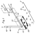
- Figure 1 is a schematic view, partly in perspective, of an apparatus according to the invention for depositing carbon dioxide snow on a surface;
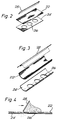
- Figure 2 shows a first arrangement of blade, screen and former for use in the apparatus shown in Figure 1;
- Figure 3 shows an alternative combination of blade, screen and former for use in the apparatus shown in Figure 1;
- Figure 4 is a side view of the apparatus shown in Figure 2.
- Referring to Figure 1 of the drawings, there is shown a
conveyer belt 2 carrying partly made food products 4. Thebelt 2 is part of a conveyor of a kind which advances the belt a unit distance at a time. Thebelt 2 extends underneath a dispensing chamber 6 for dispensing carbon dioxide snow. The chamber 6 is of generally cuboid shape. Received in an upper region thereof a generally horizontally extendingspray pipe 10 having a plurality ofspray orifices 12. Thepipe 10 communicates with a source (not shown) of liquid carbon dioxide via aconduit 14 having an automatic on-off valve 16 disposed therein and within a source of gaseous carbon dioxide (not shown) via aconduit 18 having an automatic on-offvalve 20 disposed therein. In operation, the liquid carbon dioxide can be caused to undergo a change of state on the release from thepipe 10 through theorifices 12 such that carbon dioxide snow is formed. - The floor of the chamber 6 comprises a screen (or grid) 22 of wire mesh to which is secured to a
plate 24 having dispensingapertures 26 disposed therein each of a shape, for example circular, and size corresponding to that of a surface which it is desired to set on the food products 4. - As shown in Figure 2, the screen or
grid 22 and theplate 24 may be generally planar. In an alternative embodiment of the apparatus illustrated in Figure 3, the screen orgrid 22 and theplate 24 may be of arcuate cross-section (in a plane transverse to the longitudinal axis). The arrangement of thescreen 22 and theplate 24 is such that at least some of the particles of carbon dioxide snow are retained on thescreen 22 and do not fall straight through it onto the food products 4. As shown in Figure 2 to 4, but omitted from Figure 1 for ease of illustration, a blade orwiper 28 may be reciprocated across the screen orgrid 22 so as to urge carbon dioxide snow settling thereupon through theapertures 26 and onto the articles 4 therebeneath. The blade orwiper 28 travels across the surface of the grid orscreen 22 in operation of the apparatuses shown in Figures 2 to 4 and urges carbon dioxide snow collecting on thescreen 22 across it, and when the particles of snow reach a part of thescreen 22 overlying anaperture 26, the snow falls onto the surface of the products 4 therebeneath. Typically, the blade orwiper 28 moves across the surface of the grid or screen 22 several times while the conveyor orbelt 2 is in a single position. The thickness of the deposit of carbon dioxide snow is able to be accurately controlled by appropriately selecting the mesh size of thescreen 22, the number of times the blade orwiper 28 moves across thescreen 22, and the velocity with which the blade orwiper 28 moves. Moreover, a relatively uniform deposit is able to be produced. - The blade or
wiper 28 in the apparatuses shown in Figures 2 to 4 may be driven pneumatically, hydraulically or by means of an electric motor (not shown) through a suitable transmission (not shown). - Referring now to Figure 4, it can be seen that the blade or
wiper 28 is inclined at an angle to thescreen 22 so as to impel the snow particles downwards and hence assist their passage through theapertures 26. - Referring again to Figure 1, the chamber 6 is provided with an
exhaust pipe 30 for carbon dioxide gas. Afan 32 may be disposed within thepipe 30 so as to draw carbon dioxide vapour out of the chamber 6. Thepipe 30 desirably conducts the carbon dioxide vapour away from any area in which people are working so as to avoid any risk of creating an oxygen-depleted atmosphere in such areas. - In operation, the following sequence of events takes place. First, the
belt 2 is advanced so as to bring three partially formed food products 4 which have not previously been treated with solid carbon dioxide into line with therespective apertures 26 in theplate 24. At the same time, the valve 16 is opened and a volume of liquid carbon dioxide is supplied to thepipe 10 at a pressure and temperature such that as the liquid carbon dioxide issues from theorifices 12 so it disassociates into solid carbon dioxide snow and carbon dioxide vapour. The temperature and pressure conditions needed to produce carbon dioxide in the form of snow, that is a relatively fine powder or dust, are well known in the art. Typically, the requisite temperature is in the range -56 to 0°C and the pressure in the range 6 to 21 bar. The solid carbon dioxide is formed falls under gravity and collects on the screen orgrid 22. The blade orwiper 28 is then caused to move backwards and forwards across the grid a number of times so as to urge through theapertures 26 those particles of carbon dioxide snow that do not immediately fall therethrough. Each of the three products 4 therefore receives a chosen quantity of carbon dioxide snow. The carbon dioxide vapour that is formed at the same time is exhausted from the chamber 6 by continuous operation of thefan 32. - Once the desired quantity of liquid carbon dioxide has been dispensed through the
orifices 12, the valve 16 is closed. When the solid carbon dioxide has been discharged from the dispensing chamber 6, thevalve 20 is opened and gaseous carbon dioxide at ambient temperature is passed into thepipe 10 and through theorifices 12 so as to clear any accumulation of solid carbon dioxide in the region of theorifices 12. The belt 4 is then advanced again to bring the next three products 4 underneath therespective apertures 26 of the dispensing chamber 6 and the procedure repeated. - The apparatus shown in the drawings may for example be used to set the surface of a custard or gel within a pastry case to enable a whirl of cream to be applied to the surface in a subsequent processing step without the cream becoming mixed with the gel or custard. Typically from 0 to 20g of carbon dioxide snow are applied per 80 cm² of area to give a thin covering of carbon dioxide snow. The snow then rapidly sublimes to leave a clean, dry and unmarked surface for further operations. Moreover, the heat extracted from the surface as a result of the sublimation leaves the surface stiff or solid so that it does not run during the application to it of another substance, say cream. It will be appreciated that the precise amount of solid carbon dioxide dispensed will be chosen in accordance with the temperature of the surface at the time it is brought under the dispensing chamber 6 and the temperature at which the liquid or semi-liquid substance sets.
- A number of modifications and changes may be made to the method and apparatuses described with respect to the accompanying drawings. It is possible for example to make carbon dioxide snow continuously by supplying liquid carbon dioxide continuously to the
pipe 10. In such apparatuses, it is desirable for there to be a sensor within the chamber 6 which senses the level of the solid carbon dioxide, and if it exceeds a desired level, will generate a signal effective to close the valve 16 controlling the passage of liquid carbon dioxide to thepipe 10.
Claims (12)
- A method of treating the surface of an article, comprising forming carbon dioxide snow, collecting the snow in a dispensing chamber, advancing the article under the dispensing chamber, and depositing carbon dioxide snow from the chamber through a partially occluded outlet onto a chosen area of the surface.
- A method as claimed in Claim 1, in which the surface is that of a liquid or semi-liquid food, and sublimation of the deposited snow causes the surface to set.
- A method as claimed in Claim 1 or Claim 2, in which the outlet has a screen or grid which partially occludes the outlet.
- A method as claimed in Claim 3, in which the screen or grid comprises a mesh or is perforate, the mesh size or the size of each perforation being such that the carbon dioxide snow does not pass freely therethrough.
- A method as claimed in Claim 3 or Claim 4, in which the outlet of the dispensing chamber includes a plate or other member on which the grid lies and which defines one or more apertures each corresponding to a particular surface area over which it is desired to deposit carbon dioxide snow.
- A method as claimed in any one of Claims 3 to 5, additionally including the step of moving a blade or wiper relative to the grid or screen so as to urge carbon dioxide snow therethrough.
- Apparatus for treating an article, comprising a device for forming carbon dioxide snow, a dispensing chamber for receiving the carbon dioxide snow from the device, said chamber having a partially occluded, shaped, dispensing outlet, and means for urging the carbon dioxide snow through the outlet, whereby in operation carbon dioxide snow can be deposited over a chosen area of the surface.
- Apparatus as claimed in Claim 7, in which the outlet of the dispensing chamber has a screen or grid which partially occludes the outlet.
- Apparatus as claimed in Claim 8, in which the screen or grid comprises a mesh or is perforate, the mesh size or the size of each perforation being such that the carbon dioxide snow does not pass freely therethrough.
- Apparatus as claimed in Claim 8 or Claim 9, in which the outlet of the dispensing chamber includes a plate or other member defining one or more apertures each corresponding to a particular surface area over which it is desired to deposit carbon dioxide snow.
- Apparatus as claimed in Claim 10, in which the grid or screen lies on the plate.
- Apparatus as claimed in any one of Claims 8 to 11, in which the urging means comprises a blade or wiper able to be moved across the grid or screen.
Applications Claiming Priority (2)
| Application Number | Priority Date | Filing Date | Title |
|---|---|---|---|
| GB9021234 | 1990-09-28 | ||
| GB909021234A GB9021234D0 (en) | 1990-09-28 | 1990-09-28 | Treatment of food and other products |
Publications (2)
| Publication Number | Publication Date |
|---|---|
| EP0478316A1 EP0478316A1 (en) | 1992-04-01 |
| EP0478316B1 true EP0478316B1 (en) | 1994-04-20 |
Family
ID=10682981
Family Applications (1)
| Application Number | Title | Priority Date | Filing Date |
|---|---|---|---|
| EP91308761A Expired - Lifetime EP0478316B1 (en) | 1990-09-28 | 1991-09-25 | Method and apparatus for treating food and other products with carbon dioxide snow |
Country Status (7)
| Country | Link |
|---|---|
| EP (1) | EP0478316B1 (en) |
| AU (1) | AU8471591A (en) |
| DE (1) | DE69101763T2 (en) |
| FI (1) | FI914572A (en) |
| GB (1) | GB9021234D0 (en) |
| NO (1) | NO913759L (en) |
| ZA (1) | ZA917286B (en) |
Cited By (3)
| Publication number | Priority date | Publication date | Assignee | Title |
|---|---|---|---|---|
| EP3222946A1 (en) | 2016-03-26 | 2017-09-27 | Messer France S.A.S. | Device for metering of carbon dioxide snow |
| DE102016003799A1 (en) | 2016-03-26 | 2017-09-28 | Messer France S.A.S. | Device for dosing carbon dioxide snow |
| WO2019048162A1 (en) | 2017-09-09 | 2019-03-14 | Messer Belgium N.V. | Device for metering carbon dioxide snow |
Families Citing this family (5)
| Publication number | Priority date | Publication date | Assignee | Title |
|---|---|---|---|---|
| DK0634898T3 (en) * | 1992-04-08 | 1996-02-12 | Aga Ab | Process for packaging bakery products |
| EP0634111B1 (en) * | 1993-07-12 | 1997-03-12 | Societe Des Produits Nestle S.A. | Process and apparatus for the production of a multilayered food product |
| ZA962924B (en) * | 1995-05-24 | 1996-10-25 | Pillsbury Co | System for producing a filled rolled dough product |
| FR2762190B1 (en) * | 1997-04-03 | 1999-05-14 | Carboxyque Francaise | METHOD FOR MANUFACTURING FRESH PASTE, MANUFACTURING INSTALLATION AND CORRESPONDING CARBON SNOW DEPOSIT DEVICE |
| DE102020002206A1 (en) | 2020-04-08 | 2021-10-14 | Messer France S.A.S. | Device for generating and storing carbon dioxide snow |
Family Cites Families (6)
| Publication number | Priority date | Publication date | Assignee | Title |
|---|---|---|---|---|
| US3815377A (en) * | 1970-02-26 | 1974-06-11 | L Tyree | System for cooling material using co{11 {11 snow |
| US4015440A (en) * | 1974-11-13 | 1977-04-05 | Airco, Inc. | Apparatus for depositing carbon dioxide snow |
| US4375755A (en) * | 1981-08-24 | 1983-03-08 | Barbini Richard J | Snow horns |
| AU556605B2 (en) * | 1981-11-16 | 1986-11-13 | Ptc Aerospace Inc. | Food trolley with cooling means |
| US4381649A (en) * | 1982-03-08 | 1983-05-03 | Franklin Paul R | CO2 Snow producer with heat exchanger |
| US4951472A (en) * | 1989-08-08 | 1990-08-28 | Niro Atomizer, Inc. | Process and apparatus for producing particulate frozen high water content food products |
-
1990
- 1990-09-28 GB GB909021234A patent/GB9021234D0/en active Pending
-
1991
- 1991-09-12 ZA ZA917286A patent/ZA917286B/en unknown
- 1991-09-24 AU AU84715/91A patent/AU8471591A/en not_active Abandoned
- 1991-09-25 DE DE69101763T patent/DE69101763T2/en not_active Expired - Fee Related
- 1991-09-25 NO NO91913759A patent/NO913759L/en unknown
- 1991-09-25 EP EP91308761A patent/EP0478316B1/en not_active Expired - Lifetime
- 1991-09-27 FI FI914572A patent/FI914572A/en not_active Application Discontinuation
Cited By (6)
| Publication number | Priority date | Publication date | Assignee | Title |
|---|---|---|---|---|
| EP3222946A1 (en) | 2016-03-26 | 2017-09-27 | Messer France S.A.S. | Device for metering of carbon dioxide snow |
| DE102016003800A1 (en) | 2016-03-26 | 2017-09-28 | Messer France S.A.S. | Device for dosing carbon dioxide snow |
| DE102016003799A1 (en) | 2016-03-26 | 2017-09-28 | Messer France S.A.S. | Device for dosing carbon dioxide snow |
| WO2017167620A1 (en) | 2016-03-26 | 2017-10-05 | Messer France S.A.S. | Device for metering carbon dioxide snow |
| WO2019048162A1 (en) | 2017-09-09 | 2019-03-14 | Messer Belgium N.V. | Device for metering carbon dioxide snow |
| US11378434B2 (en) | 2017-09-09 | 2022-07-05 | Messer Belgium N.V. | Device for metering carbon dioxide snow |
Also Published As
| Publication number | Publication date |
|---|---|
| EP0478316A1 (en) | 1992-04-01 |
| DE69101763D1 (en) | 1994-05-26 |
| NO913759D0 (en) | 1991-09-25 |
| FI914572A0 (en) | 1991-09-27 |
| GB9021234D0 (en) | 1990-11-14 |
| ZA917286B (en) | 1993-01-27 |
| FI914572A (en) | 1992-03-29 |
| DE69101763T2 (en) | 1994-08-18 |
| NO913759L (en) | 1992-03-30 |
| AU8471591A (en) | 1992-04-02 |
Similar Documents
| Publication | Publication Date | Title |
|---|---|---|
| US7810446B2 (en) | Continuous coating of gum materials | |
| US4188768A (en) | Apparatus for producing frozen confections | |
| US5299426A (en) | Freezing process and apparatus | |
| US7322311B2 (en) | Continuous coatings of gum products | |
| EP0478316B1 (en) | Method and apparatus for treating food and other products with carbon dioxide snow | |
| NL8203336A (en) | CANDY PRODUCTS, METHODS, AND APPARATUS FOR THE PREPARATION THEREOF. | |
| US4679496A (en) | Apparatus for producing laminated products | |
| US6418834B1 (en) | Apparatus for treating an item during travel of the item along a treating trough | |
| CN1102313A (en) | A multilayer food product and a process for the production | |
| US4778685A (en) | Method for producing laminated products | |
| US2784567A (en) | Rapid refrigeration of foodstuffs | |
| JPH0314764B2 (en) | ||
| AU715465B2 (en) | Cooling apparatus | |
| US4652287A (en) | Apparatus for forming solid carbon dioxide | |
| CN108885043B (en) | Device for metering carbon dioxide snow | |
| US4858524A (en) | Apparatus for producing laminated products | |
| CA1099567A (en) | Preparation of frozen raw battered products | |
| JP4295622B2 (en) | Flowable solid dispensing device and method of use | |
| JPH02135041A (en) | Apparatus for automatically making and supplying breads, cakes, etc. | |
| US20050095329A1 (en) | Method and apparatus of coating articles | |
| US3328176A (en) | Cheese treating methods | |
| US4752197A (en) | Apparatus for producing frozen confections | |
| US4304085A (en) | Cocktail filling machine and method | |
| RU2281655C2 (en) | Method for producing of ice-cream and apparatus for performing the same | |
| CA1246391A (en) | Method and apparatus for producing frozen confections including edible particulate material |
Legal Events
| Date | Code | Title | Description |
|---|---|---|---|
| PUAI | Public reference made under article 153(3) epc to a published international application that has entered the european phase |
Free format text: ORIGINAL CODE: 0009012 |
|
| AK | Designated contracting states |
Kind code of ref document: A1 Designated state(s): BE DE DK ES FR GB IT NL SE |
|
| 17P | Request for examination filed |
Effective date: 19920622 |
|
| 17Q | First examination report despatched |
Effective date: 19930707 |
|
| GRAA | (expected) grant |
Free format text: ORIGINAL CODE: 0009210 |
|
| ITF | It: translation for a ep patent filed |
Owner name: BARZANO' E ZANARDO MILANO S.P.A. |
|
| AK | Designated contracting states |
Kind code of ref document: B1 Designated state(s): BE DE DK ES FR GB IT NL SE |
|
| PG25 | Lapsed in a contracting state [announced via postgrant information from national office to epo] |
Ref country code: SE Free format text: LAPSE BECAUSE OF FAILURE TO SUBMIT A TRANSLATION OF THE DESCRIPTION OR TO PAY THE FEE WITHIN THE PRESCRIBED TIME-LIMIT Effective date: 19940420 Ref country code: FR Effective date: 19940420 Ref country code: DK Effective date: 19940420 |
|
| REF | Corresponds to: |
Ref document number: 69101763 Country of ref document: DE Date of ref document: 19940526 |
|
| PG25 | Lapsed in a contracting state [announced via postgrant information from national office to epo] |
Ref country code: ES Free format text: LAPSE BECAUSE OF FAILURE TO SUBMIT A TRANSLATION OF THE DESCRIPTION OR TO PAY THE FEE WITHIN THE PRESCRIBED TIME-LIMIT Effective date: 19940731 |
|
| PGFP | Annual fee paid to national office [announced via postgrant information from national office to epo] |
Ref country code: SE Payment date: 19940812 Year of fee payment: 4 |
|
| PGFP | Annual fee paid to national office [announced via postgrant information from national office to epo] |
Ref country code: DK Payment date: 19940815 Year of fee payment: 4 |
|
| PGFP | Annual fee paid to national office [announced via postgrant information from national office to epo] |
Ref country code: ES Payment date: 19940914 Year of fee payment: 4 |
|
| EN | Fr: translation not filed | ||
| PLBE | No opposition filed within time limit |
Free format text: ORIGINAL CODE: 0009261 |
|
| STAA | Information on the status of an ep patent application or granted ep patent |
Free format text: STATUS: NO OPPOSITION FILED WITHIN TIME LIMIT |
|
| 26N | No opposition filed | ||
| PGFP | Annual fee paid to national office [announced via postgrant information from national office to epo] |
Ref country code: NL Payment date: 19950811 Year of fee payment: 5 |
|
| PGFP | Annual fee paid to national office [announced via postgrant information from national office to epo] |
Ref country code: DE Payment date: 19950818 Year of fee payment: 5 |
|
| PGFP | Annual fee paid to national office [announced via postgrant information from national office to epo] |
Ref country code: BE Payment date: 19950824 Year of fee payment: 5 |
|
| PG25 | Lapsed in a contracting state [announced via postgrant information from national office to epo] |
Ref country code: BE Effective date: 19960930 |
|
| BERE | Be: lapsed |
Owner name: THE BOC GROUP P.L.C. Effective date: 19960930 |
|
| PG25 | Lapsed in a contracting state [announced via postgrant information from national office to epo] |
Ref country code: NL Effective date: 19970401 |
|
| NLV4 | Nl: lapsed or anulled due to non-payment of the annual fee |
Effective date: 19970401 |
|
| PG25 | Lapsed in a contracting state [announced via postgrant information from national office to epo] |
Ref country code: DE Effective date: 19970603 |
|
| REG | Reference to a national code |
Ref country code: GB Ref legal event code: IF02 |
|
| PGFP | Annual fee paid to national office [announced via postgrant information from national office to epo] |
Ref country code: GB Payment date: 20030917 Year of fee payment: 13 |
|
| PG25 | Lapsed in a contracting state [announced via postgrant information from national office to epo] |
Ref country code: GB Free format text: LAPSE BECAUSE OF NON-PAYMENT OF DUE FEES Effective date: 20040925 |
|
| GBPC | Gb: european patent ceased through non-payment of renewal fee |
Effective date: 20040925 |
|
| PG25 | Lapsed in a contracting state [announced via postgrant information from national office to epo] |
Ref country code: IT Free format text: LAPSE BECAUSE OF NON-PAYMENT OF DUE FEES;WARNING: LAPSES OF ITALIAN PATENTS WITH EFFECTIVE DATE BEFORE 2007 MAY HAVE OCCURRED AT ANY TIME BEFORE 2007. THE CORRECT EFFECTIVE DATE MAY BE DIFFERENT FROM THE ONE RECORDED. Effective date: 20050925 |