EP0478244B1 - Ink cartridge and ink jet apparatus usable with ink cartridge - Google Patents
Ink cartridge and ink jet apparatus usable with ink cartridge Download PDFInfo
- Publication number
- EP0478244B1 EP0478244B1 EP91308605A EP91308605A EP0478244B1 EP 0478244 B1 EP0478244 B1 EP 0478244B1 EP 91308605 A EP91308605 A EP 91308605A EP 91308605 A EP91308605 A EP 91308605A EP 0478244 B1 EP0478244 B1 EP 0478244B1
- Authority
- EP
- European Patent Office
- Prior art keywords
- cartridge
- ink
- projection
- case
- aperture
- Prior art date
- Legal status (The legal status is an assumption and is not a legal conclusion. Google has not performed a legal analysis and makes no representation as to the accuracy of the status listed.)
- Expired - Lifetime
Links
Images


Classifications
-
- B—PERFORMING OPERATIONS; TRANSPORTING
- B41—PRINTING; LINING MACHINES; TYPEWRITERS; STAMPS
- B41J—TYPEWRITERS; SELECTIVE PRINTING MECHANISMS, i.e. MECHANISMS PRINTING OTHERWISE THAN FROM A FORME; CORRECTION OF TYPOGRAPHICAL ERRORS
- B41J2/00—Typewriters or selective printing mechanisms characterised by the printing or marking process for which they are designed
- B41J2/005—Typewriters or selective printing mechanisms characterised by the printing or marking process for which they are designed characterised by bringing liquid or particles selectively into contact with a printing material
- B41J2/01—Ink jet
- B41J2/17—Ink jet characterised by ink handling
- B41J2/175—Ink supply systems ; Circuit parts therefor
- B41J2/17503—Ink cartridges
- B41J2/17526—Electrical contacts to the cartridge
-
- B—PERFORMING OPERATIONS; TRANSPORTING
- B41—PRINTING; LINING MACHINES; TYPEWRITERS; STAMPS
- B41J—TYPEWRITERS; SELECTIVE PRINTING MECHANISMS, i.e. MECHANISMS PRINTING OTHERWISE THAN FROM A FORME; CORRECTION OF TYPOGRAPHICAL ERRORS
- B41J2/00—Typewriters or selective printing mechanisms characterised by the printing or marking process for which they are designed
- B41J2/005—Typewriters or selective printing mechanisms characterised by the printing or marking process for which they are designed characterised by bringing liquid or particles selectively into contact with a printing material
- B41J2/01—Ink jet
- B41J2/17—Ink jet characterised by ink handling
- B41J2/175—Ink supply systems ; Circuit parts therefor
- B41J2/17503—Ink cartridges
- B41J2/17513—Inner structure
-
- B—PERFORMING OPERATIONS; TRANSPORTING
- B41—PRINTING; LINING MACHINES; TYPEWRITERS; STAMPS
- B41J—TYPEWRITERS; SELECTIVE PRINTING MECHANISMS, i.e. MECHANISMS PRINTING OTHERWISE THAN FROM A FORME; CORRECTION OF TYPOGRAPHICAL ERRORS
- B41J2/00—Typewriters or selective printing mechanisms characterised by the printing or marking process for which they are designed
- B41J2/005—Typewriters or selective printing mechanisms characterised by the printing or marking process for which they are designed characterised by bringing liquid or particles selectively into contact with a printing material
- B41J2/01—Ink jet
- B41J2/17—Ink jet characterised by ink handling
- B41J2/175—Ink supply systems ; Circuit parts therefor
- B41J2/17503—Ink cartridges
- B41J2/1752—Mounting within the printer
Definitions
- the present invention provides an ink jet printer and an ink cartridge for use in the ink jet printer.
- EP-A-0412459 forms part of the state of the art by virtue of Article 54 (3) EPC. It discloses an ink cartridge which comprises a case, an ink container provided in the case, an ink absorbing material also provided in the case, an ink supply port in one end of the case for permitting supply of ink from the container and an ink receiving port also in said one end of the case for permitting residual ink to pass to the absorbing material in the case.
- the cartridge is for use with an ink jet printer which comprises a housing having an aperture in which the ink cartridge can be received, printer ink supply means within the aperture which takes the form of a needle which becomes inserted into the cartridge when the cartridge is in its operative position within the aperture so as to receive ink from the cartridge, and a waste ink delivery pipe that fits into an inlet port on the cartridge so as to return residual ink to the cartridge.
- printer ink supply means within the aperture which takes the form of a needle which becomes inserted into the cartridge when the cartridge is in its operative position within the aperture so as to receive ink from the cartridge
- a waste ink delivery pipe that fits into an inlet port on the cartridge so as to return residual ink to the cartridge.
- a protective cover is moved between a closed position in which the needle and the waste ink delivery pipe are inaccessible when no cartridge is present within the aperture and an open position to permit the cartridge to enter the aperture and pass to its operative position.
- Locking means is provided to secure the cover in its closed position and is releasable by the cartridge as the cartridge is inserted into the aperture.
- Locking members located at opposite sides of the cover are moved apart by projections on the side of the cartridge as the cartridge is inserted into the aperture.
- Cartridge systems in which a hollow needle of a printer pierces a bag of an ink container, and in which there is a risk of the operator's hand coming into contact with the needle are also disclosed in US-A-4074284 and Japanese Laid Open Utility Model No 180734/1986 (Application No 62973/1985).
- Cartridges comprising a flexible ink container and providing for collection of residual ink are disclosed in US-A-4119034 and 4695824.
- the present invention provides a more simple and compact mechanism for releasing the protective cover.
- it is easier for the person inserting the cartridge to judge which way up the cartridge should be inserted into the aperture.
- the invention provides an ink jet printer having the features set out in claim 1 of the accompanying claims and an ink cartridge having the features of claim 12 of the accompanying claims.
- the cartridge has a forwardly facing projection which prevents the ink supply port and the ink receiving port from coming into contact with a surface on which the ink cartridge is stood.
- the projection may be dimensioned so that the ink cartridge cannot be made to stand stably on a flat surface when its ink output portion is facing downwardly.
- Figure 1 is a perspective view of an ink jet recording apparatus according to an embodiment of the present invention without its top cover.
- Figures 2A and 2B are a perspective and a partial sectional view of a structure of an ink cartridge mounting portion of the ink jet recording apparatus.
- Figure 3 is a sectional view of an ink cartridge according to an embodiment of the present invention.
- Figure 4 is a perspective view illustrating interconnection between the ink cartridge and the main assembly of the recording apparatus.
- Figure 5 illustrates the positional relation of the connection.
- Figures 6A, 6B, 6C, 6D and 6E illustrate inconveniences arising when the positional relation in this embodiment is not used.
- Figures 7A and 7B are partial enlarged view of an ink cartridge and the positional relation in an improved modification of Figures 4 and 5 arrangement.
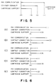
- Figures 8A and 8B are a block diagram of a control system used with the structure of Figure 7 and a flow chart showing the sequential operations thereof.
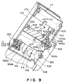
- Figure 9 is a bottom view of the ink cartridge inserting portion.
- Figures 10A, 10B and 11 are sectional views of an ink cartridge inserting portion.
- Figure 12 is a perspective view of an ink cartridge.
- Figure 13 shows an ink cartridge wherein it stand on a table.
- Figure 14 is a perspective view of an ink cartridge having a pulling seal.
- FIG. 1 is a perspective view of an ink jet recording apparatus according to an embodiment of the present invention wherein a cover of the apparatus has been removed.
- the ink jet recording apparatus comprises a recording head 1 in the form of a chip and a carriage 2 for mounting the recording head 1 thereon and for scanningly moving the recording head along a recording material (a sheet of paper).
- the carriage 2 is provided, as will be described in detail hereinafter, a supporting member for detachably mounting the recording head 1 and a cover member (chain lines) for protecting a base plate which constitute a part of the recording head 1 and on which a head driver circuit or the like is printed.
- the recording head 1 has 64 ejection outlets at its end surface, and the ejection outlets communicates with the respective ink passages. Behind the ink passages, a common liquid chamber is provided to supply the respective liquid passages with the ink.
- an electrothermal transducer for generating thermal energy contributable to ejecting droplets of the ink through the ejection outlet and electrode wiring for supplying electric power to the electrothermal transducers.
- the electrothermal transducer and the electrode wiring are formed on the base plate made of silicon or the like through film forming processes. By laminating partition walls and top plate or the like made of resin or glass material, on the base plate, the ejection outlets, the ink passages and the common ink chambers are constituted. Further behind on the recording head 1, driving circuit is formed in the form of a print to drive the electrothermal transducers in accordance with the recording signals.
- the carriage 2 is provided with a connector base 12 through a connector 9 at a position behind the recording head 1 mounting position.
- the connector base plate 12 is provided with a connector 9 for connection with the recording head 1 and a connector for connection with a flexible cable connected with a control circuit of a main assembly control system 400 ( Figure 8A).
- the connector base plate 12 has capacitors and resistors or the like which function to compensate voltage drop through the flexible cable and to prevent introduction of noise.
- the connector base plate 12 is supported on a sliding member, as will be described hereinafter and slides together with the opening and closing motion of the cover member so that the connector 9 is brought into contact with the contact of the recording head 1.
- the carriage 2 is engaged with a guiding shaft 3 through the engaging portion 2a for sliding and rotational movement.
- the guiding shaft 3 extends over a range longer than the width of the recording sheet 6 in the direction perpendicular to the direction of the recording material feeding.
- the carriage 2 is connected with a part of a belt (not shown) stretched in a direction parallel with the guiding shaft 3.
- the belt is driven by a carriage motor (not shown)
- the carriage 2 moves along the guiding shaft 3 in the scanning manner.
- the carriage 2 and the recording head 1 rotates along the guiding shaft 3 by the weights thereof.
- the weights are also effective to urge a sheet confining plate 8 which will be described hereinafter, through a sliding member 17 which is provided on the carriage 2 and slides on the sheet confining plate.
- the recording head 1 is spaced from the recording sheet 6 with a predetermined clearance therebetween irrespective of the thickness of the recording sheet 6.
- the recording sheet 6 which is automatically fed out of a sheet feeding cassette (not shown) or manually fed out, is fed into the main assembly of the recording apparatus through a sheet inlet 7 constituted by an upper paper guide 7a and a lower paper guide 7b.
- the upper paper guide 7a has an extension constituting the curved sheet confining plate 8.
- the sheet confining plate 8 urges the recording sheet 6 to a platen roller 5.
- the material is so selected that the friction resulting between the sheet confining plate 8 and the recording sheet 6 under the urging force is smaller than the friction between the sheet feeding roller 5 and the recording sheet 6.
- the lower paper guide 7b extends to a position where the sheet confining plate 8 is in parallel with the platen roller 5.
- the recording sheet 6 is supplied through the sheet inlet 7 and is fed upwardly together with the rotation of the sheet feeding roller 28 one by one line. At this time, the recording sheet 6 slides on a plate-like platen 7 while the interval between the recording head 1 and the recording sheet 6 being maintained at a predetermined level by the sheet confining plate 8 and the platen 7.
- a pinch roller 29 is pressed on a periphery of the sheet feeding roller 5 by the resiliency of a leaf spring 29a.
- the recording head 1 during its scanning movement, ejects or discharges ink droplets to the recording zone of the recording sheet faced thereto, thus effecting the recording operation for one line.
- character, the characters, the images or the like are recorded.
- the recording sheet 6 now having the recorded image or the like is discharged onto the discharge tray (not shown) by discharging roller 4 and spurs 40A and 40B disposed above the sheet conveying passage.
- Five pairs of spurs 40A and 40B are provided for five pairs of discharging rollers 4.
- a spur cleaner are disposed. In Figure 1, the member for supporting the spur cleaner and the spur cleaner are omitted.
- the spur 40A presses the recording sheet 6 to the discharging roller 4, and the spur 40B confines the conveying direction of the recording sheet 6 in cooperation with the platen 7.
- the discharging roller 4 is rotated so as to have a peripheral speed larger than that of the sheet feeding roller 5, so that the recording zone of the recording sheet 6 is stretched upwardly, by which the recording sheet 6 is prevented from being away from the platen 7, thus assuring the proper recording operation in the recording zone.
- the structure Adjacent a home position which is continuous with the scanning zone of the recording head 1, various structures for effecting ejection recovery for the recording head 1 are provided.
- the structure includes a blade 26 for removing droplets, dust or the like on the ejection side surface having the ejection outlets by a wiping action, an absorbing member 25 for removing the droplets on the ejection side surface by absorption, and a cap for capping the ejection side surface to sealing the ejection side surface, effecting idle ink ejection and sucking the ink.
- They are supported integrally on a supporting member 14 which is movable toward and away from the recording head 1 moving zone, so as to carry out the respective operations at proper times.
- the ink sucking operation using the cap 13 is carried out with a pump 24 which is communicating with the gap 13 through a hollow portion of the movable supporting member 14 and a tube.
- a pump 24 which is communicating with the gap 13 through a hollow portion of the movable supporting member 14 and a tube.
- the rotational driving force of the feed motor 21 is used to rotate the sheet feeding roller 5, the discharging roller 4 and operates the ejection recovery mechanism, more particularly, the movement of the cap 13, the blade 26 and the absorbing member 25 and the pump 24.
- the rotational driving force of the feed motor 21 mounted on the frame of the main assembly is first transmitted to a transmission and switching gear train 19.
- the selective switching is effected by movement of an unshown selecting gear operable in association with the scanning movement of the recording head 1, the movement to the home position or the ejection recovery position and the stoppage thereat.
- the rotations of the gears in the gear train 19 is transmitted to the sheet discharging roller 4 and the sheet feeding roller 5 via an intermediate gear 20. It is also transmitted to the integral cap 13 or the like by way of a cam 16 and also transmitted to the pump 24 via pump gear 22 and a pump cam 23.
- the ink is supplied to the recording head 1 from the ink cartridge 27 mounted on the main assembly of the recording apparatus through a flexible tube 100 ( Figures 1, 2 and 4) which can follow the movement of the carriage 2. More particularly, the ink is supplied to the recording head 1 from the ink cartridge 27 through a tube 100 connecting the hollow needle 314 and the recording head 1.
- the position of the carriage 2 is detected by counting the number of steps actuated by the carriage motor (not shown) with the reference position provided by interrelation between a home position sensor 11 of the carriage 2 and a home position detecting flag 31 adjacent an end of the moving zone of the carriage 2. These operations are controlled by the controller 400 ( Figure 8A) of the main assembly.
- Figures 2A and 2B show the mounting portion 30 for the ink cartridge.
- a reference numeral 302 is an ink cartridge inserting portion for receiving the ink cartridge 27.
- a contact holder 304 functions to hold leaf spring contacts 306A and 306B functioning as a means for reading information provided on the ink cartridge 27.
- a latching portion 308 and the inserting portion 302 By engagement between a latching portion 308 and the inserting portion 302, it is combined into the inserting portion 302.
- Figure 2A shows the state before the holder 304 is combined with the inserting portion 302.
- a connector 312 functions to connect the contacts 306a and 306b with the controller 400 of the main assembly.
- a hollow needle 314 pierces in an ink containing bladder and has three holes 316 for receiving the ink, at its end.
- an ink supply tube 100 is connected, and the other end of the tube 100 is connected to the common ink chamber in the head chip 110 of the recording head 1.
- An ink remaining amount detecting means may be disposed at a proper part in the ink supply system.
- a residual ink receiving pipe 318 enters the ink cartridge 27 through an opening 350 ( Figure 4) and feed the residual ink to the ink absorbing material 344.
- the residual ink is produced by the refreshing process from the ink supply system or the common ink chamber or by the ink ejection recovery processing.
- a click 320 functions to fix the ink cartridge 27, and it is provided at each side of the inserting portion 302.
- an engaging portion 322 of the click 320 flexes by its flexibility upon engagement with the side surface of the cartridge 27 when it is inserted, so that the insertion of the cartridge 27 is permitted.
- the engaging portion 322 restores by its elasticity, by which the click 320 engages into the recess 322.
- the cartridge 27 is fixed in place.
- the ink cartridge 27 also comprises an ink absorbing material 344 for absorbing the residual ink.
- the ink absorbing material 344 is disposed between the ink bladder 340 and the bottom surface 27b of the case 27a of the cartridge 27 so as to cover substantially the entire bottom surface 27b. As shown in Figure 4, a part thereof extends substantially vertically at the rear side of the opening 305.
- Figure 4 illustrates the connection between the ink cartridge 27 and the main assembly.
- a wiring pattern 346 on the ink cartridge 27 functions to connect the contacts 306A and 306B.
- the controller 400 of the main assembly detects whether the ink cartridge 27 is mounted or not.
- the pattern may have a resistance depending on the color or density or the like of the ink stored in the ink cartridge 27. Then, the controller 400 is also informed of the characteristics.
- the ink cartridge 27 When the ink cartridge 27 is inserted into the main assembly of the recording apparatus, it passes by an inserting position (1) where the ink communication is established by the insertion of the needle 314 through the plug 342 to place the holes 316 in the ink bladder 340, an inserting position (2) wherein the contacts 306A and 306B are connected by the wiring pattern 346 with each other, and an inserting position (3) in which the click 320 is in engagement with the recess 332 to fix the ink cartridge 27. Various dimensions and positional relations are determined so that the inserting positions come in this order.
- the needle 314 When the operator inserts the cartridge 27 into the apparatus, the needle 314 first pierces in the ink bladder 340.
- the contacts 306A and 306B are brought into electric contact through the resistance pattern 346.
- the click 320 is brought into engagement with the recess 332, so that the cartridge 27 is fixed in place in the mounting portion 30 in the main assembly.
- the ink cartridge 27 accommodates the residual ink, and therefore, it is desirable that the residual ink pipe 318 is brought into the ink cartridge 27 at the inserting position (1).
- Figure 5 shows the above-described positional relations.
- the ink cartridge 27 finally abuts the part of the main assembly at the inserting position (4). Therefore, the range between the position (3) and position (4), is the movable range in which the cartridge 24 is movable by the play of the engagement between the click 320 and the recess 332, or the range through which the cartridge 27 is movable after the engagement between the click 320 and the recess 332 and until its abut the back end of the main assembly.
- Figure 6 illustrates the inconveniences when the above positional relations are not satisfied.
- the controller 400 of the main assembly does not correctly discriminate the insertion of the ink cartridge.
- the contacts are established prior to the communication of the ink established.
- the controller 400 will erroneously discriminate the completion of the cartridge insertion and can start a certain operation. If this occurs, the air may be introduced into the ink supply system by the needle 314. This also applies to the case of Figure 6C.
- the operator stops the inserting operation because of the clicking sound produced, the ink communication is not established.
- Figure 7A shows a structure of a further improved apparatus.
- the wiring pattern is divided into two parts.
- the front pattern 346A with respect to the cartridge inserting direction is allotted the function of establishing electric connection between the contact 306A and 306B, and the rear pattern 346B is allotted of representing ink color and density or the like by changing the resistance.
- Figure 7B shows a range in which the ink communication is established, a range in which the electric connection is established between the contact 306A and 306B through the pattern 346A, a range in which they are contacted only through the pattern 346B, and a range in which the cartridge is properly fixed.
- a position (1) is a limit position for the ink communication
- a position (3) is a limit position for fixing the cartridge 27, and a position (4) is a cartridge 27 abutment position.
- a position (2A) is a trailing side limit position (with respect to the cartridge inserting direction) for the electric connection between the contact 306A and 306B through the pattern 346A.
- a position (2B) is a trailing limit position in which the contact 306A and 306B are away from the pattern 346A, and they are contacted only with the pattern 346B so that the resistance of the pattern 346B is readable.
- the position (2B) is preferably the same as or in the neighborhood of the position (3), and particularly in the neighborhood of the position (3) where the click 320 is not engaged with the recess 332, and therefore, the cartridge 27 is easily retracted.
- Figure 8A shows the major part of the control system. It comprises a controller 400. It may be in the form of a microcomputer comprising a CPU for controlling the process shown in Figure 8B and for controlling the entirety of the apparatus, ROM storing the program or the like for the process and working RAM.
- Designated by a reference numeral 410 is a detector for detecting the resistance between the contacts 306A and 306B. When the resistance is zero, it indicates that the pattern 346A short-circuits the contacts. If it is the infinity, it indicates that the ink cartridge 27 is not mounted. When the resistance has a predetermined level, the fact indicates that the ink cartridge 27 is properly mounted in place in the mounting portion 30.
- Designated by a reference numeral 420 is an information part having a display for a message and/or sound producing means. Reference I designates stopping signal for various parts.
- Figures 8B shows an example of the operational steps of this embodiment. This operation may be started when the main switch is actuated, when the ink cartridge 27 is exchanged or at proper timing during the recording.
- step S1 When the process is started, the resistance is read at step S1. If it is the infinity, it is discriminated that the cartridge 27 is not mounted. Therefore, the operation proceeds to step S3 where the operations of various parts are maintained at rest. At step S5, the operator is promoted to insert the cartridge 27 into the recording apparatus.
- step S7 If the resistance is zero, it is discriminated that the cartridge 27 is easily retracted. Therefore, the operation proceeds to step S7, where the operations of various parts are stopped. Subsequently, at step S9, the operator is promoted to assuredly set the cartridge 27.
- the cartridge 27 has already been assuredly fixed.
- the information (ink color or the like) of the cartridge, indicated by the resistance, is read, and the setting operations corresponding to the information are carried out at step S11.
- the controller 400 is capable of recognizing such the situation, and stops the operation, and thereafter, the proper insertion of the cartridge 27 is promoted to the operator. In this manner, the liability that the cartridge 27 is released against intention can be notified to the operator beforehand.
- the cartridge and the inserting position may have another structure if the above described positional relations relating to the ink communication, the cartridge information reading and the cartridge retention, are assured.
- the retention of the cartridge is not limited to that by the click and the recess structure.
- the leading of the information inherent to the ink cartridge is not limited to the electric one. It may be an optical one.
- the residual ink is introduced into the cartridge, but the cartridge may have only the function of ink supply.
- a cover 401 is provided at the inlet portion of the inserting or mounting portion 30 so as to prevent the operator's finger or other foreign matters from contacting the ink receiving needle 314 in the maintenance operation or the like.
- the cover 401 is prevented from opening except for the cartridge 27 insertion time.
- Figure 9 is a bottom view of the inserting portion and corresponds to the view taken along lines a in Figure 2.
- Figure 10 is a sectional view taken along a line vertical to the ink cartridge inserting direction.
- Figure 10A shows the situation when the ink cartridge 27 is not mounted, and
- Figure 10B shows the situation when it is mounted.
- Figure 11 is a sectional view taken along a line parallel with the ink cartridge inserting direction.
- the cover 401 is disposed so as to block the cartridge inserting path it is made of a metal plate having a thickness of 0.8 mm, for example. It has an area substantially equal to the sectional area of the ink cartridge. Therefore, when the cartridge inserting path 33 is blocked by the cover 401, it does not provide enough space for permitting insertion of the operator's finger or other foreign matters beyond the cover 401. Therefore, the needle 314 and/or the residual ink pipe 318 are protected from them.
- the cover 401 is rotatable about a recess 403 in the sealing of the mounting portion 30 with which a hook 404 of the cover.
- the cover 401 When the cartridge 27 is inserted, the cover 401 is urged upwardly by the insertion of the cartridge 27 and rotates about the recess 403 until it is contacted to the sealing to permit the insertion of the cartridge 27.
- a pawl 406a of a stopper 406 When the cartridge 27 is not in the inserting portion, a pawl 406a of a stopper 406 is projected into the rotational movement range of the cover 401, so that the cover 401 is prevented from opening by the pawl 406a.
- the cover 401 blocks the cartridge insertion path 33 and also prevents the introduction of foreign matters beyond the cover 401. Further below the pawl 406a of the stopper 406, there is an inclined portion 406b below a bottom end of the cover 401.
- the stopper 406 has a pin 406c at its upper position, and the pin 406c is supported in a bearing 407 of the mounting portion. An upper end of a spring 406d integral with the stopper 406 is engaged with a frame 410 of the main assembly so as to urge the stopper 406 to the cartridge mounting portion.
- the stopper 406b rotates in the retracting direction from the cartridge insertion path 33 about the pin 406c against the spring force by the spring 406d, by which the pawl 406a is released from the cover 401, thus permitting opening of the cover 401.
- the cover 401 is permitted to retract from the cartridge insertion path 33.
- the cartridge 27 has a projection 405a on a front surface 405 (leading side with respect to the cartridge inserting direction) at a position corresponding to the tapered portion 406b of the stopper 406 upon insertion of the cartridge.
- the projection 405a When the cartridge 27 is inserted into the inserting path 33, the projection 405a is faced to the tapered portion 406b. Therefore, when the cartridge is in the process of being inserted, the projection 405a enters the gap between the cover 401 and the frame 408 beyond the cover 401 until it contacts the tapered portion 406b of the stopper 406.
- the projection 405 lowers the tapered portion 406b so as to retract the tapered portion 406b away from the insertion path 33, until the pawl 406a of the stopper 406 is released from the cover 401. Then, the cover 401 is permitted to retract away from the insertion path, thus permitting further insertion of the cartridge 27. Thereafter, the front side 405 of the cartridge 27 abuts directly the cover 406, by which the cover 401 is raised by the cartridge 27.
- the needle 314 and the residual ink pipe 318 are introduced through the plug 342 and the opening 350 of the cartridge 27. Then, the ink communication with established, and the presence of the cartridge is detected, with the cartridge prepared for receiving the residual ink.
- the cartridge 27 is fixed or retained in place in the mounting portion 30 by the engagement between the click 320 and the cartridge recess 332.
- the inside plate 409 of the mounting portion is provided with a whole 408 ( Figure 9) for receiving the projection 405a of the cartridge.
- the stopper 406 is normally urged in the direction of locking the cover 401 by the contact of the spring 406d to a part of the main assembly.
- the clearance between the cover 401 and the frame 408 is approximately 4 mm when the cover 401 is at its closing position, and the top S of the tapered surface 406b of the stopper 406 is at a position approximately 3 mm away from the cover 401 toward the inside.
- the height of the projection 405a of the cartridge 27 is approximately 2 mm from the bottom surface, and the length thereof is approximately 2 mm.
- the projection of the cartridge and the latching of the main assembly is not limitedly provided to the lower side, but it may be disposed at the lateral side or the like, as required by the structure of the main assembly. They may be provided at the opposite sides.
- the dimensions of the ink jet cartridge 27 are as follows: 1: 109 mm: 2; 79.6 mm: 3; 25.5 mm: 4: 14 mm: 5; 6 mm: 6; 42.8 mm: 7; 20.8 mm: 8; 12.5 mm: 9; 17.5 mm: 10; 13.4 mm: 11; 7 mm: 12; 6 mm: 13; 12 mm: 14 and 15; 6 mm: 16; 4 mm: 17; 2.5 mm: 18; 10 mm: 19 and 20; 6 mm: 21; 2 mm: 22; 4.5 mm: 23; 3 mm:
- An inclined surface 500 at each of the left and right top of the cartridge 27 is provided for preventing erroneous insertion.
- the top 27c ( Figure 3) of the leading side of the cartridge case 27a abuts the limiting plate 32 of the main assembly ( Figures 1, 10A and 10B), so that the loading of the cartridge 27 is prevented.
- the inclined surface 500 is effective to escape from the limiting plate 32, so that the cartridge 27 is permitted to be further inserted.
- the configuration at the top end of the cartridge case 27a is not limited to the inclined or tapered surface but may be changed in accordance with the shape of the limiting plate.
- a pulling seal 35 is bonded on the top of the ink cartridge 27.
- the seal 35 is bent and is extended to the rear side 27c of the cartridge case 27a.
- An end thereof constitutes a tongue 35a covering a projection 27d on the rear side 27c.
- the ink cartridge in this embodiment is provided with the projection 405a at the side having the plug 342 and/or the opening 350. Therefore, the following advantageous effects are provided.
- the cover opening and closing mechanism is engageable with the projection of the cartridge, and therefore, it requires only small additional space, and the structure is simple.
- the present invention is particularly suitably usable in an ink jet recording head and recording apparatus wherein thermal energy by an electrothermal transducer, laser beam or the like is used to cause a change of state of the ink to eject or discharge the ink. This is because the high density of the picture elements and the high resolution of the recording are possible.
- the typical structure and the operational principle are preferably the ones disclosed in U.S. Patent Nos. 4,723,129 and 4,740,796.
- the principle and structure are applicable to a so-called on-demand type recording system and a continuous type recording system.
- it is suitable for the on-demand type because the principle is such that at least one driving signal is applied to an electrothermal transducer disposed on a liquid (ink) retaining sheet or liquid passage, the driving signal being enough to provide such a quick temperature rise beyond a departure from nucleation boiling point, by which the thermal energy is provided by the electrothermal transducer to produce film boiling on the heating portion of the recording head, whereby a bubble can be formed in the liquid (ink) corresponding to each of the driving signals.
- the liquid (ink) is ejected through an ejection outlet to produce at least one droplet.
- the driving signal is preferably in the form of a pulse, because the development and contraction of the bubble can be effected instantaneously, and therefore, the liquid (ink) is ejected with quick response.
- the driving signal in the form of the pulse is preferably such as disclosed in U.S. patents Nos. 4,463,359 and 4,345,262.
- the temperature increasing rate of the heating surface is preferably such as disclosed in U.S. Patent No. 4,313,124.
- the structure of the recording head may be as shown in U.S. Patent Nos. 4,558,333 and 4,459,600 wherein the heating portion is disposed at a bent portion, as well as the structure of the combination of the ejection outlet, liquid passage and the electrothermal transducer as disclosed in the above-mentioned patents.
- the present invention is applicable to the structure disclosed in Japanese Laid-Open Patent Application No. 123670/1984 wherein a common slit is used as the ejection outlet for plural electrothermal transducers, and to the structure disclosed in Japanese Laid-Open Patent Application No. 138461/1984 wherein an opening for absorbing pressure wave of the thermal energy is formed corresponding to the ejecting portion. This is because the present invention is effective to perform the recording operation with certainty and at high efficiency irrespective of the type of the recording head.
- the present invention is effectively applicable to a so-called full-line type recording head having a length corresponding to the maximum recording width.
- a recording head may comprise a single recording head and plural recording head combined to cover the maximum width.
- the present invention is applicable to a serial type recording head wherein the recording head is fixed on the main assembly, to a replaceable chip type recording head which is connected electrically with the main apparatus and can be supplied with the ink when it is mounted in the main assembly, or to a cartridge type recording head having an integral ink container.
- the provisions of the recovery means and/or the auxiliary means for the preliminary operation are preferable, because they can further stabilize the effects of the present invention.
- preliminary heating means which may be the electrothermal transducer, an additional heating element or a combination thereof.
- means for effecting preliminary ejection (not for the recording operation) can stabilize the recording operation.
- the recording head mountable may be a single corresponding to a single color ink, or may be plural corresponding to the plurality of ink materials having different recording color or density.
- the present invention is effectively applicable to an apparatus having at least one of a monochromatic mode mainly with black, a multi-color mode with different color ink materials and/or a full-color mode using the mixture of the colors, which may be an integrally formed recording unit or a combination of plural recording heads.
- the ink has been liquid. It may be, however, an ink material which is solidified below the room temperature but liquefied at the room temperature. Since the ink is controlled within the temperature not lower than 30 °C and not higher than 70 °C to stabilize the viscosity of the ink to provide the stabilized ejection in usual recording apparatus of this type, the ink may be such that it is liquid within the temperature range when the recording signal is the present invention is applicable to other types of ink. In one of them, the temperature rise due to the thermal energy is positively prevented by consuming it for the state change of the ink from the solid state to the liquid state. Another ink material is solidified when it is left, to prevent the evaporation of the ink.
- the ink is liquefied, and the liquefied ink may be ejected.
- Another ink material may start to be solidified at the time when it reaches the recording material.
- the present invention is also applicable to such an ink material as is liquefied by the application of the thermal energy.
- Such an ink material may be retained as a liquid or solid material in through holes or recesses formed in a porous sheet as disclosed in Japanese Laid-Open Patent Application No. 56847/1979 and Japanese Laid-Open Patent Application No. 71260/1985. The sheet is faced to the electrothermal transducers. The most effective one for the ink materials described above is the film boiling system.
- the ink jet recording apparatus may be used as an output terminal of an information processing apparatus such as computer or the like, as a copying apparatus combined with an image reader or the like, or as a facsimile machine having information sending and receiving functions.
- the small and simple structure is enough to prevent the erroneous mounting of the ink cartridge and from the contamination with the ink.
Abstract
Description
- The present invention provides an ink jet printer and an ink cartridge for use in the ink jet printer.
- EP-A-0412459 forms part of the state of the art by virtue of Article 54 (3) EPC. It discloses an ink cartridge which comprises a case, an ink container provided in the case, an ink absorbing material also provided in the case, an ink supply port in one end of the case for permitting supply of ink from the container and an ink receiving port also in said one end of the case for permitting residual ink to pass to the absorbing material in the case. The cartridge is for use with an ink jet printer which comprises a housing having an aperture in which the ink cartridge can be received, printer ink supply means within the aperture which takes the form of a needle which becomes inserted into the cartridge when the cartridge is in its operative position within the aperture so as to receive ink from the cartridge, and a waste ink delivery pipe that fits into an inlet port on the cartridge so as to return residual ink to the cartridge. In order to protect the users fingers from the needle, which may be contaminated with ink, a protective cover is moved between a closed position in which the needle and the waste ink delivery pipe are inaccessible when no cartridge is present within the aperture and an open position to permit the cartridge to enter the aperture and pass to its operative position.
- Locking means is provided to secure the cover in its closed position and is releasable by the cartridge as the cartridge is inserted into the aperture. In the structure shown in Figures 26 to 28 of EP-A-0142459, locking members located at opposite sides of the cover are moved apart by projections on the side of the cartridge as the cartridge is inserted into the aperture.
- Cartridge systems in which a hollow needle of a printer pierces a bag of an ink container, and in which there is a risk of the operator's hand coming into contact with the needle are also disclosed in US-A-4074284 and Japanese Laid Open Utility Model No 180734/1986 (Application No 62973/1985). Cartridges comprising a flexible ink container and providing for collection of residual ink are disclosed in US-A-4119034 and 4695824.
- The present invention provides a more simple and compact mechanism for releasing the protective cover. In an embodiment of the cartridge, it is easier for the person inserting the cartridge to judge which way up the cartridge should be inserted into the aperture.
- The invention provides an ink jet printer having the features set out in
claim 1 of the accompanying claims and an ink cartridge having the features ofclaim 12 of the accompanying claims. - The cartridge has a forwardly facing projection which prevents the ink supply port and the ink receiving port from coming into contact with a surface on which the ink cartridge is stood. The projection may be dimensioned so that the ink cartridge cannot be made to stand stably on a flat surface when its ink output portion is facing downwardly.
- How the invention may be put into effect will now be described, by way of example only, with reference to the accompanying drawings.
- Figure 1 is a perspective view of an ink jet recording apparatus according to an embodiment of the present invention without its top cover.
- Figures 2A and 2B are a perspective and a partial sectional view of a structure of an ink cartridge mounting portion of the ink jet recording apparatus.
- Figure 3 is a sectional view of an ink cartridge according to an embodiment of the present invention.
- Figure 4 is a perspective view illustrating interconnection between the ink cartridge and the main assembly of the recording apparatus.
- Figure 5 illustrates the positional relation of the connection.
- Figures 6A, 6B, 6C, 6D and 6E illustrate inconveniences arising when the positional relation in this embodiment is not used.
- Figures 7A and 7B are partial enlarged view of an ink cartridge and the positional relation in an improved modification of Figures 4 and 5 arrangement.
- Figures 8A and 8B are a block diagram of a control system used with the structure of Figure 7 and a flow chart showing the sequential operations thereof.
- Figure 9 is a bottom view of the ink cartridge inserting portion.
- Figures 10A, 10B and 11 are sectional views of an ink cartridge inserting portion.
- Figure 12 is a perspective view of an ink cartridge.
- Figure 13 shows an ink cartridge wherein it stand on a table.
- Figure 14 is a perspective view of an ink cartridge having a pulling seal.
- Referring to the accompanying drawings the preferred embodiments of the present inventions will be described.
- Figure 1 is a perspective view of an ink jet recording apparatus according to an embodiment of the present invention wherein a cover of the apparatus has been removed. The ink jet recording apparatus comprises a
recording head 1 in the form of a chip and acarriage 2 for mounting therecording head 1 thereon and for scanningly moving the recording head along a recording material (a sheet of paper). Thecarriage 2 is provided, as will be described in detail hereinafter, a supporting member for detachably mounting therecording head 1 and a cover member (chain lines) for protecting a base plate which constitute a part of therecording head 1 and on which a head driver circuit or the like is printed. - The
recording head 1 has 64 ejection outlets at its end surface, and the ejection outlets communicates with the respective ink passages. Behind the ink passages, a common liquid chamber is provided to supply the respective liquid passages with the ink. Each of the ink passages corresponding to each of 64 ejection outlets, an electrothermal transducer for generating thermal energy contributable to ejecting droplets of the ink through the ejection outlet and electrode wiring for supplying electric power to the electrothermal transducers. - The electrothermal transducer and the electrode wiring are formed on the base plate made of silicon or the like through film forming processes. By laminating partition walls and top plate or the like made of resin or glass material, on the base plate, the ejection outlets, the ink passages and the common ink chambers are constituted. Further behind on the
recording head 1, driving circuit is formed in the form of a print to drive the electrothermal transducers in accordance with the recording signals. - The
carriage 2 is provided with aconnector base 12 through aconnector 9 at a position behind therecording head 1 mounting position. Theconnector base plate 12 is provided with aconnector 9 for connection with therecording head 1 and a connector for connection with a flexible cable connected with a control circuit of a main assembly control system 400 (Figure 8A). Theconnector base plate 12 has capacitors and resistors or the like which function to compensate voltage drop through the flexible cable and to prevent introduction of noise. Theconnector base plate 12 is supported on a sliding member, as will be described hereinafter and slides together with the opening and closing motion of the cover member so that theconnector 9 is brought into contact with the contact of therecording head 1. - The
carriage 2 is engaged with a guidingshaft 3 through the engaging portion 2a for sliding and rotational movement. The guidingshaft 3 extends over a range longer than the width of therecording sheet 6 in the direction perpendicular to the direction of the recording material feeding. Thecarriage 2 is connected with a part of a belt (not shown) stretched in a direction parallel with the guidingshaft 3. When the belt is driven by a carriage motor (not shown), thecarriage 2 moves along the guidingshaft 3 in the scanning manner. Thecarriage 2 and therecording head 1 rotates along the guidingshaft 3 by the weights thereof. The weights are also effective to urge asheet confining plate 8 which will be described hereinafter, through a slidingmember 17 which is provided on thecarriage 2 and slides on the sheet confining plate. Thus, therecording head 1 is spaced from therecording sheet 6 with a predetermined clearance therebetween irrespective of the thickness of therecording sheet 6. - The
recording sheet 6 which is automatically fed out of a sheet feeding cassette (not shown) or manually fed out, is fed into the main assembly of the recording apparatus through asheet inlet 7 constituted by an upper paper guide 7a and alower paper guide 7b. The upper paper guide 7a has an extension constituting the curvedsheet confining plate 8. Thesheet confining plate 8 urges therecording sheet 6 to aplaten roller 5. The material is so selected that the friction resulting between thesheet confining plate 8 and therecording sheet 6 under the urging force is smaller than the friction between thesheet feeding roller 5 and therecording sheet 6. Thelower paper guide 7b extends to a position where thesheet confining plate 8 is in parallel with theplaten roller 5. - The
recording sheet 6 is supplied through thesheet inlet 7 and is fed upwardly together with the rotation of the sheet feeding roller 28 one by one line. At this time, therecording sheet 6 slides on a plate-like platen 7 while the interval between therecording head 1 and therecording sheet 6 being maintained at a predetermined level by thesheet confining plate 8 and theplaten 7. Apinch roller 29 is pressed on a periphery of thesheet feeding roller 5 by the resiliency of aleaf spring 29a. - The
recording head 1, during its scanning movement, ejects or discharges ink droplets to the recording zone of the recording sheet faced thereto, thus effecting the recording operation for one line. By repeating the recording operation and the subsequent sheet feeding operation by one line, character, the characters, the images or the like are recorded. Therecording sheet 6 now having the recorded image or the like is discharged onto the discharge tray (not shown) bydischarging roller 4 andspurs 40A and 40B disposed above the sheet conveying passage. Five pairs ofspurs 40A and 40B are provided for five pairs ofdischarging rollers 4. Between the spurs, a spur cleaner are disposed. In Figure 1, the member for supporting the spur cleaner and the spur cleaner are omitted. Thespur 40A presses therecording sheet 6 to thedischarging roller 4, and the spur 40B confines the conveying direction of therecording sheet 6 in cooperation with theplaten 7. The dischargingroller 4 is rotated so as to have a peripheral speed larger than that of thesheet feeding roller 5, so that the recording zone of therecording sheet 6 is stretched upwardly, by which therecording sheet 6 is prevented from being away from theplaten 7, thus assuring the proper recording operation in the recording zone. - Adjacent a home position which is continuous with the scanning zone of the
recording head 1, various structures for effecting ejection recovery for therecording head 1 are provided. The structure includes a blade 26 for removing droplets, dust or the like on the ejection side surface having the ejection outlets by a wiping action, an absorbingmember 25 for removing the droplets on the ejection side surface by absorption, and a cap for capping the ejection side surface to sealing the ejection side surface, effecting idle ink ejection and sucking the ink. They are supported integrally on a supportingmember 14 which is movable toward and away from therecording head 1 moving zone, so as to carry out the respective operations at proper times. The ink sucking operation using thecap 13 is carried out with apump 24 which is communicating with thegap 13 through a hollow portion of the movable supportingmember 14 and a tube. When the recording head is capped by thecap 13, a hole formed in acap arm 17 mounted on a side surface of the cap supporting member is engaged with a projection of thecarriage 2 so that therecording head 1 is prevented from backward rotation, thus assuring the capping of thecap 13 for the ejection side surface. - The rotational driving force of the
feed motor 21 is used to rotate thesheet feeding roller 5, the dischargingroller 4 and operates the ejection recovery mechanism, more particularly, the movement of thecap 13, the blade 26 and the absorbingmember 25 and thepump 24. The rotational driving force of thefeed motor 21 mounted on the frame of the main assembly is first transmitted to a transmission and switchinggear train 19. In thegear train 19, the selective switching is effected by movement of an unshown selecting gear operable in association with the scanning movement of therecording head 1, the movement to the home position or the ejection recovery position and the stoppage thereat. The rotations of the gears in thegear train 19 is transmitted to thesheet discharging roller 4 and thesheet feeding roller 5 via anintermediate gear 20. It is also transmitted to theintegral cap 13 or the like by way of acam 16 and also transmitted to thepump 24 viapump gear 22 and apump cam 23. - The ink is supplied to the
recording head 1 from theink cartridge 27 mounted on the main assembly of the recording apparatus through a flexible tube 100 (Figures 1, 2 and 4) which can follow the movement of thecarriage 2. More particularly, the ink is supplied to therecording head 1 from theink cartridge 27 through atube 100 connecting thehollow needle 314 and therecording head 1. The position of thecarriage 2 is detected by counting the number of steps actuated by the carriage motor (not shown) with the reference position provided by interrelation between a home position sensor 11 of thecarriage 2 and a homeposition detecting flag 31 adjacent an end of the moving zone of thecarriage 2. These operations are controlled by the controller 400 (Figure 8A) of the main assembly. - The description will be described as to the mounting
portion 30 to which theink cartridge 27 is mounted, and also the description will be made as to the ink cartridge. - Figures 2A and 2B show the mounting
portion 30 for the ink cartridge. In Figure 2A, designated by areference numeral 302 is an ink cartridge inserting portion for receiving theink cartridge 27. Acontact holder 304 functions to holdleaf spring contacts ink cartridge 27. By engagement between a latchingportion 308 and the insertingportion 302, it is combined into the insertingportion 302. Figure 2A shows the state before theholder 304 is combined with the insertingportion 302. Aconnector 312 functions to connect the contacts 306a and 306b with thecontroller 400 of the main assembly. - A
hollow needle 314 pierces in an ink containing bladder and has threeholes 316 for receiving the ink, at its end. To the other end of theneedle 314, anink supply tube 100 is connected, and the other end of thetube 100 is connected to the common ink chamber in the head chip 110 of therecording head 1. An ink remaining amount detecting means may be disposed at a proper part in the ink supply system. - A residual
ink receiving pipe 318 enters theink cartridge 27 through an opening 350 (Figure 4) and feed the residual ink to theink absorbing material 344. The residual ink is produced by the refreshing process from the ink supply system or the common ink chamber or by the ink ejection recovery processing. - A
click 320 functions to fix theink cartridge 27, and it is provided at each side of the insertingportion 302. As shown in Figure 2B, an engagingportion 322 of theclick 320 flexes by its flexibility upon engagement with the side surface of thecartridge 27 when it is inserted, so that the insertion of thecartridge 27 is permitted. When arecess 322 of thecartridge 27 reaches the position where theclick 320 is disposed, the engagingportion 322 restores by its elasticity, by which theclick 320 engages into therecess 322. Thus, thecartridge 27 is fixed in place. - Referring to Figures 3 and 4, the
ink cartridge 27 will be described. - It comprises a
flexible ink bladder 340 for containing the supply of the ink and is provided with aplug 342 made of rubber or the like. Theink bladder 340 is hermetically sealed by theplug 342. When theink cartridge 27 is mounted into the mountingportion 30 of the main assembly, theneedle 314 of the main assembly pierces into theplug 342 to a sufficient degree, by which the ink communication is established. Anannular ring 342b protects therubber plug 342. Theink cartridge 27 also comprises anink absorbing material 344 for absorbing the residual ink. Theink absorbing material 344 is disposed between theink bladder 340 and thebottom surface 27b of thecase 27a of thecartridge 27 so as to cover substantially the entirebottom surface 27b. As shown in Figure 4, a part thereof extends substantially vertically at the rear side of the opening 305. Thus, the ink introduced from the main assembly through theresidual ink pipe 318 is assuredly distributed over substantially the entirety of thebottom surface 27b. - Figure 4 illustrates the connection between the
ink cartridge 27 and the main assembly. Awiring pattern 346 on theink cartridge 27 functions to connect thecontacts contact controller 400 of the main assembly detects whether theink cartridge 27 is mounted or not. The pattern may have a resistance depending on the color or density or the like of the ink stored in theink cartridge 27. Then, thecontroller 400 is also informed of the characteristics. - When the
ink cartridge 27 is inserted into the main assembly of the recording apparatus, it passes by an inserting position (1) where the ink communication is established by the insertion of theneedle 314 through theplug 342 to place theholes 316 in theink bladder 340, an inserting position (2) wherein thecontacts wiring pattern 346 with each other, and an inserting position (3) in which theclick 320 is in engagement with therecess 332 to fix theink cartridge 27. Various dimensions and positional relations are determined so that the inserting positions come in this order. When the operator inserts thecartridge 27 into the apparatus, theneedle 314 first pierces in theink bladder 340. When thecartridge 27 is further inserted into the main assembly, thecontacts resistance pattern 346. When thecartridge 27 is further inserted, theclick 320 is brought into engagement with therecess 332, so that thecartridge 27 is fixed in place in the mountingportion 30 in the main assembly. In this embodiment, theink cartridge 27 accommodates the residual ink, and therefore, it is desirable that theresidual ink pipe 318 is brought into theink cartridge 27 at the inserting position (1). - Figure 5 shows the above-described positional relations. In Figure 5, the
ink cartridge 27 finally abuts the part of the main assembly at the inserting position (4). Therefore, the range between the position (3) and position (4), is the movable range in which thecartridge 24 is movable by the play of the engagement between theclick 320 and therecess 332, or the range through which thecartridge 27 is movable after the engagement between theclick 320 and therecess 332 and until its abut the back end of the main assembly. - Figure 6 illustrates the inconveniences when the above positional relations are not satisfied. In the positional relation shown in Figure 6A, even if the cartridge is properly fixed, the information on the characteristics of the cartridge is not read by the
contact controller 400 of the main assembly does not correctly discriminate the insertion of the ink cartridge. With the positional relation shown in Figure 6B, the contacts are established prior to the communication of the ink established. Thecontroller 400 will erroneously discriminate the completion of the cartridge insertion and can start a certain operation. If this occurs, the air may be introduced into the ink supply system by theneedle 314. This also applies to the case of Figure 6C. In addition, if the operator stops the inserting operation because of the clicking sound produced, the ink communication is not established. - With the positional relations shown in Figures 6D and 6E, the
needle 314 is not correctly inserted even though the cartridge is properly fixed. Or, the electric connection between the contacts will not be stabilized. - If the positional relations shown in Figure 5 are used, the ink communication, the electric connection between the contacts and the cartridge fixing occur in this order when the cartridge is inserted. Therefore, what is required for the operator is to confirm the cartridge fixing on the basis of the click sound. Even if the
controller 400 starts the operation immediately in response to the establishment of the electric connection, no air is introduced into the ink supply system. In addition, even if thecartridge 27 is removed during the operation of thecontroller 400, thecontroller 400 is able to detect the event before the ink communication is destroyed. Therefore, no inconveniences arise if the operation is stopped in response thereto. - Figure 7A shows a structure of a further improved apparatus. In this embodiment, the wiring pattern is divided into two parts. The
front pattern 346A with respect to the cartridge inserting direction is allotted the function of establishing electric connection between thecontact rear pattern 346B is allotted of representing ink color and density or the like by changing the resistance. - Figure 7B shows a range in which the ink communication is established, a range in which the electric connection is established between the
contact pattern 346A, a range in which they are contacted only through thepattern 346B, and a range in which the cartridge is properly fixed. - A position (1) is a limit position for the ink communication, a position (3) is a limit position for fixing the
cartridge 27, and a position (4) is acartridge 27 abutment position. A position (2A) is a trailing side limit position (with respect to the cartridge inserting direction) for the electric connection between thecontact pattern 346A. A position (2B) is a trailing limit position in which thecontact pattern 346A, and they are contacted only with thepattern 346B so that the resistance of thepattern 346B is readable. Here, the position (2B) is preferably the same as or in the neighborhood of the position (3), and particularly in the neighborhood of the position (3) where theclick 320 is not engaged with therecess 332, and therefore, thecartridge 27 is easily retracted. - Because of the positional relations shown in Figure 7B, the same advantageous effects as in the case of Figure 5 are provided. With this embodiment, the further advantages are provided when the following operation is carried out.
- Figure 8A shows the major part of the control system. It comprises a
controller 400. It may be in the form of a microcomputer comprising a CPU for controlling the process shown in Figure 8B and for controlling the entirety of the apparatus, ROM storing the program or the like for the process and working RAM. Designated by areference numeral 410 is a detector for detecting the resistance between thecontacts pattern 346A short-circuits the contacts. If it is the infinity, it indicates that theink cartridge 27 is not mounted. When the resistance has a predetermined level, the fact indicates that theink cartridge 27 is properly mounted in place in the mountingportion 30. Designated by areference numeral 420 is an information part having a display for a message and/or sound producing means. Reference I designates stopping signal for various parts. - Figures 8B shows an example of the operational steps of this embodiment. This operation may be started when the main switch is actuated, when the
ink cartridge 27 is exchanged or at proper timing during the recording. - When the process is started, the resistance is read at step S1. If it is the infinity, it is discriminated that the
cartridge 27 is not mounted. Therefore, the operation proceeds to step S3 where the operations of various parts are maintained at rest. At step S5, the operator is promoted to insert thecartridge 27 into the recording apparatus. - If the resistance is zero, it is discriminated that the
cartridge 27 is easily retracted. Therefore, the operation proceeds to step S7, where the operations of various parts are stopped. Subsequently, at step S9, the operator is promoted to assuredly set thecartridge 27. - If the resistance has a predetermined level, the
cartridge 27 has already been assuredly fixed. The information (ink color or the like) of the cartridge, indicated by the resistance, is read, and the setting operations corresponding to the information are carried out at step S11. - If the
click 320 and therecess 332 are not engaged despite the operator inserts thecartridge 27 into the apparatus, or when the engagement is released for some reason or another, the retention of the cartridge is not sufficient, therefore, the cartridge is easily released. In such an occasion, thecontact pattern 346A, and therefore, thecontroller 400 is unable to read the information inherent to thecartridge 27. In this embodiment, thecontroller 400 is capable of recognizing such the situation, and stops the operation, and thereafter, the proper insertion of thecartridge 27 is promoted to the operator. In this manner, the liability that thecartridge 27 is released against intention can be notified to the operator beforehand. - In this embodiment, the cartridge and the inserting position may have another structure if the above described positional relations relating to the ink communication, the cartridge information reading and the cartridge retention, are assured. For example, the retention of the cartridge is not limited to that by the click and the recess structure. The leading of the information inherent to the ink cartridge is not limited to the electric one. It may be an optical one. In the foregoing embodiment, the residual ink is introduced into the cartridge, but the cartridge may have only the function of ink supply.
- In this embodiment, a
cover 401 is provided at the inlet portion of the inserting or mountingportion 30 so as to prevent the operator's finger or other foreign matters from contacting theink receiving needle 314 in the maintenance operation or the like. Thecover 401 is prevented from opening except for thecartridge 27 insertion time. - Referring to Figures 9 - 11, the structure will be described. Figure 9 is a bottom view of the inserting portion and corresponds to the view taken along lines a in Figure 2. Figure 10 is a sectional view taken along a line vertical to the ink cartridge inserting direction. Figure 10A shows the situation when the
ink cartridge 27 is not mounted, and Figure 10B shows the situation when it is mounted. Figure 11 is a sectional view taken along a line parallel with the ink cartridge inserting direction. - The
cover 401 is disposed so as to block the cartridge inserting path it is made of a metal plate having a thickness of 0.8 mm, for example. It has an area substantially equal to the sectional area of the ink cartridge. Therefore, when thecartridge inserting path 33 is blocked by thecover 401, it does not provide enough space for permitting insertion of the operator's finger or other foreign matters beyond thecover 401. Therefore, theneedle 314 and/or theresidual ink pipe 318 are protected from them. Thecover 401 is rotatable about arecess 403 in the sealing of the mountingportion 30 with which ahook 404 of the cover. - When the
cartridge 27 is inserted, thecover 401 is urged upwardly by the insertion of thecartridge 27 and rotates about therecess 403 until it is contacted to the sealing to permit the insertion of thecartridge 27. When thecartridge 27 is not in the inserting portion, apawl 406a of astopper 406 is projected into the rotational movement range of thecover 401, so that thecover 401 is prevented from opening by thepawl 406a. Thus, thecover 401 blocks thecartridge insertion path 33 and also prevents the introduction of foreign matters beyond thecover 401. Further below thepawl 406a of thestopper 406, there is aninclined portion 406b below a bottom end of thecover 401. - When the
cover 401 is at the closing position, the top portion S of the taperedportion 406b is further inside of thecover 401. Therefore, the taperedportion 406b is kept from the operator's finger or the like. Thestopper 406 has apin 406c at its upper position, and thepin 406c is supported in abearing 407 of the mounting portion. An upper end of aspring 406d integral with thestopper 406 is engaged with aframe 410 of the main assembly so as to urge thestopper 406 to the cartridge mounting portion. When aprojection 405a of thecartridge 27 pushes the taperedportion 406b, thestopper 406b rotates in the retracting direction from thecartridge insertion path 33 about thepin 406c against the spring force by thespring 406d, by which thepawl 406a is released from thecover 401, thus permitting opening of thecover 401. In other words, thecover 401 is permitted to retract from thecartridge insertion path 33. Thecartridge 27 has aprojection 405a on a front surface 405 (leading side with respect to the cartridge inserting direction) at a position corresponding to the taperedportion 406b of thestopper 406 upon insertion of the cartridge. - When the
cartridge 27 is inserted into the insertingpath 33, theprojection 405a is faced to the taperedportion 406b. Therefore, when the cartridge is in the process of being inserted, theprojection 405a enters the gap between thecover 401 and theframe 408 beyond thecover 401 until it contacts the taperedportion 406b of thestopper 406. When thecartridge 405 is further inserted, theprojection 405 lowers the taperedportion 406b so as to retract the taperedportion 406b away from theinsertion path 33, until thepawl 406a of thestopper 406 is released from thecover 401. Then, thecover 401 is permitted to retract away from the insertion path, thus permitting further insertion of thecartridge 27. Thereafter, thefront side 405 of thecartridge 27 abuts directly thecover 406, by which thecover 401 is raised by thecartridge 27. - The relations between the
projection 405a of thecartridge 27 and thefront side 405 of the cartridge and between thecover 401 and thestopper 406, are as follows: - (1) The
projection 406a lowers the taperedsurface 406b of thestopper 406; - (2) The
pawl 406a of the stopper is released from thecover 401; and - (3) The
front side 405 of thecartridge 27 raises thecover 401. - Then, as described hereinbefore, the
needle 314 and theresidual ink pipe 318 are introduced through theplug 342 and theopening 350 of thecartridge 27. Then, the ink communication with established, and the presence of the cartridge is detected, with the cartridge prepared for receiving the residual ink. In addition, thecartridge 27 is fixed or retained in place in the mountingportion 30 by the engagement between theclick 320 and thecartridge recess 332. - The
inside plate 409 of the mounting portion is provided with a whole 408 (Figure 9) for receiving theprojection 405a of the cartridge. As described hereinbefore, thestopper 406 is normally urged in the direction of locking thecover 401 by the contact of thespring 406d to a part of the main assembly. - In this embodiment, the clearance between the
cover 401 and theframe 408 is approximately 4 mm when thecover 401 is at its closing position, and the top S of the taperedsurface 406b of thestopper 406 is at a position approximately 3 mm away from thecover 401 toward the inside. The height of theprojection 405a of thecartridge 27 is approximately 2 mm from the bottom surface, and the length thereof is approximately 2 mm. With this sizes, it is not possible to release thestopper 406 by the operator's finger without intention. Therefore, thecover 401 is not opened against the intention in the maintenance operation or the like. - The projection of the cartridge and the latching of the main assembly is not limitedly provided to the lower side, but it may be disposed at the lateral side or the like, as required by the structure of the main assembly. They may be provided at the opposite sides.
- Referring to Figure 12, the dimensions of the
ink jet cartridge 27 are as follows: 1: 109 mm: 2; 79.6 mm: 3; 25.5 mm: 4: 14 mm: 5; 6 mm: 6; 42.8 mm: 7; 20.8 mm: 8; 12.5 mm: 9; 17.5 mm: 10; 13.4 mm: 11; 7 mm: 12; 6 mm: 13; 12 mm: 14 and 15; 6 mm: 16; 4 mm: 17; 2.5 mm: 18; 10 mm: 19 and 20; 6 mm: 21; 2 mm: 22; 4.5 mm: 23; 3 mm: - An
inclined surface 500 at each of the left and right top of thecartridge 27 is provided for preventing erroneous insertion. - More particularly, when the operator erroneously tried to insert the
cartridge 27 up-side-down into the mounting or insertingportion 30, the top 27c (Figure 3) of the leading side of thecartridge case 27a abuts the limitingplate 32 of the main assembly (Figures 1, 10A and 10B), so that the loading of thecartridge 27 is prevented. When thecartridge 27 is correctly inserted, theinclined surface 500 is effective to escape from the limitingplate 32, so that thecartridge 27 is permitted to be further inserted. The configuration at the top end of thecartridge case 27a is not limited to the inclined or tapered surface but may be changed in accordance with the shape of the limiting plate. - As shown in Figure 12, a pulling
seal 35 is bonded on the top of theink cartridge 27. Theseal 35 is bent and is extended to therear side 27c of thecartridge case 27a. An end thereof constitutes atongue 35a covering aprojection 27d on therear side 27c. When thecartridge 27 is to be taken out of the main assembly, thetongue 35a is peeled off thecase 27a, and the cartridge is pulled out by the pullingseal 35a. - The ink cartridge in this embodiment is provided with the
projection 405a at the side having theplug 342 and/or theopening 350. Therefore, the following advantageous effects are provided. - (1) The erroneous loading can be prevented beforehand. When the cartridge is loaded, the projection at the predetermined position opens a protection cover. The cover opens only when the ink cartridge is inserted. Therefore, even if the operator erroneously tries to load a different kind of cartridge, the cover does not open, thus preventing erroneous loading of the cartridge.
- (2) The amounting operation is easier. In this embodiment, the direction of the projection is the same as the ink cartridge inserting direction, and therefore, the operator can easily judge the inserting direction from the configuration of the ink cartridge. Therefore, the operator quickly understood the inserting direction without difficulty.
- (3) Contamination by the ink can be prevented. This is because usually, the operator does not try to put the ink cartridge so that the projection contacts the table or the like. The plug or the opening which may be contaminated with the ink are not contacted to the table or the like. Because of the dimensions of the ink cartridge described hereinbefore, if the operator places the
ink cartridge 27 so that it stands with the rubber plug 342 (oropening 342a) side facing down, or even if the operator tries to do so, theplug 342 or the opening 305 does not contact thesurface 600 of the table or the like. Thus, the table or the like is prevented from being contaminated with the ink.
Whether the ink cartridge stands or can not stands in that manner is dependent on the thickness of the projection or the configuration thereof. The present invention is intended to cover both cases. - (4) The mechanism for opening and closing the cover is simplified, and the size thereof is minimized.
- In this embodiment, the cover opening and closing mechanism is engageable with the projection of the cartridge, and therefore, it requires only small additional space, and the structure is simple.
- The present invention is particularly suitably usable in an ink jet recording head and recording apparatus wherein thermal energy by an electrothermal transducer, laser beam or the like is used to cause a change of state of the ink to eject or discharge the ink. This is because the high density of the picture elements and the high resolution of the recording are possible.
- The typical structure and the operational principle are preferably the ones disclosed in U.S. Patent Nos. 4,723,129 and 4,740,796. The principle and structure are applicable to a so-called on-demand type recording system and a continuous type recording system. Particularly, however, it is suitable for the on-demand type because the principle is such that at least one driving signal is applied to an electrothermal transducer disposed on a liquid (ink) retaining sheet or liquid passage, the driving signal being enough to provide such a quick temperature rise beyond a departure from nucleation boiling point, by which the thermal energy is provided by the electrothermal transducer to produce film boiling on the heating portion of the recording head, whereby a bubble can be formed in the liquid (ink) corresponding to each of the driving signals. By the production, development and contraction of the the bubble, the liquid (ink) is ejected through an ejection outlet to produce at least one droplet. The driving signal is preferably in the form of a pulse, because the development and contraction of the bubble can be effected instantaneously, and therefore, the liquid (ink) is ejected with quick response. The driving signal in the form of the pulse is preferably such as disclosed in U.S. patents Nos. 4,463,359 and 4,345,262. In addition, the temperature increasing rate of the heating surface is preferably such as disclosed in U.S. Patent No. 4,313,124.
- The structure of the recording head may be as shown in U.S. Patent Nos. 4,558,333 and 4,459,600 wherein the heating portion is disposed at a bent portion, as well as the structure of the combination of the ejection outlet, liquid passage and the electrothermal transducer as disclosed in the above-mentioned patents. In addition, the present invention is applicable to the structure disclosed in Japanese Laid-Open Patent Application No. 123670/1984 wherein a common slit is used as the ejection outlet for plural electrothermal transducers, and to the structure disclosed in Japanese Laid-Open Patent Application No. 138461/1984 wherein an opening for absorbing pressure wave of the thermal energy is formed corresponding to the ejecting portion. This is because the present invention is effective to perform the recording operation with certainty and at high efficiency irrespective of the type of the recording head.
- The present invention is effectively applicable to a so-called full-line type recording head having a length corresponding to the maximum recording width. Such a recording head may comprise a single recording head and plural recording head combined to cover the maximum width.
- In addition, the present invention is applicable to a serial type recording head wherein the recording head is fixed on the main assembly, to a replaceable chip type recording head which is connected electrically with the main apparatus and can be supplied with the ink when it is mounted in the main assembly, or to a cartridge type recording head having an integral ink container.
- The provisions of the recovery means and/or the auxiliary means for the preliminary operation are preferable, because they can further stabilize the effects of the present invention. As for such means, there are capping means for the recording head, cleaning means therefor, pressing or sucking means, preliminary heating means which may be the electrothermal transducer, an additional heating element or a combination thereof. Also, means for effecting preliminary ejection (not for the recording operation) can stabilize the recording operation.
- As regards the variation of the recording head mountable, it may be a single corresponding to a single color ink, or may be plural corresponding to the plurality of ink materials having different recording color or density. The present invention is effectively applicable to an apparatus having at least one of a monochromatic mode mainly with black, a multi-color mode with different color ink materials and/or a full-color mode using the mixture of the colors, which may be an integrally formed recording unit or a combination of plural recording heads.
- Furthermore, in the foregoing embodiment, the ink has been liquid. It may be, however, an ink material which is solidified below the room temperature but liquefied at the room temperature. Since the ink is controlled within the temperature not lower than 30 °C and not higher than 70 °C to stabilize the viscosity of the ink to provide the stabilized ejection in usual recording apparatus of this type, the ink may be such that it is liquid within the temperature range when the recording signal is the present invention is applicable to other types of ink. In one of them, the temperature rise due to the thermal energy is positively prevented by consuming it for the state change of the ink from the solid state to the liquid state. Another ink material is solidified when it is left, to prevent the evaporation of the ink. In either of the cases, the application of the recording signal producing thermal energy, the ink is liquefied, and the liquefied ink may be ejected. Another ink material may start to be solidified at the time when it reaches the recording material. The present invention is also applicable to such an ink material as is liquefied by the application of the thermal energy. Such an ink material may be retained as a liquid or solid material in through holes or recesses formed in a porous sheet as disclosed in Japanese Laid-Open Patent Application No. 56847/1979 and Japanese Laid-Open Patent Application No. 71260/1985. The sheet is faced to the electrothermal transducers. The most effective one for the ink materials described above is the film boiling system.
- The ink jet recording apparatus may be used as an output terminal of an information processing apparatus such as computer or the like, as a copying apparatus combined with an image reader or the like, or as a facsimile machine having information sending and receiving functions.
- As described in the foregoing, according to the present invention, the small and simple structure is enough to prevent the erroneous mounting of the ink cartridge and from the contamination with the ink.
- While the invention has been described with reference to the structures disclosed herein, it is not confined to the details set forth and this application is intended to cover such modifications or changes as may come within the scope of the following claims.
Claims (33)
- An ink jet printer comprising a housing (30) having an aperture for receiving an ink cartridge, printer ink supply means (100) within said aperture couplable with the cartridge when the latter is in its operative position within the aperture to receive ink from the cartridge, a waste ink delivery port (318) provided within the aperture, said port being couplable with an inlet port (350) on said cartridge to return residual ink to said cartridge, a protective cover (401) movable between a closed position to render the ink supply means inaccessible when no cartridge is present within the aperture and an open position to permit entry of the cartridge into the aperture to the operative position, and locking means to secure said cover in its closed position releasable by said cartridge on insertion of the latter into the aperture, wherein(a) said locking means (406, 406a, 406b) is located inside the cover (401) with respect to the direction of insertion of the cartridge; and(b) said protective cover is shaped so as to provide a space between a peripheral edge thereof and a wall of the aperture, through which space said locking means (406, 406a, 406b) is accessible and contactable by a projection (405a) provided on the leading end of the ink cartridge, taken in the direction of insertion, to effect release of the locking means and permit the cover to be moved to its open position.
- An ink jet printer as claimed in claim 1, wherein the cover is pivotable about a substantially horizontal axis at an upper edge thereof, said space being formed between the bottom edge of the cover and the aperture wall.
- An ink jet printer as claimed in claim 2, wherein said locking means comprises an arm (406) pivotable about an axis disposed parallel to the direction of insertion and located close to an upper corner of said aperture, said arm having a first projection (406a) which serves to block the path of movement of said cover so that the cover is held in its closed position, and a second projection (406b), engageable by the projection (405a) on the cartridge, which second projection extends into the path of movement of said cartridge at the level of the space, when no cartridge is present in the aperture, whereby on insertion of the cartridge the projection thereon arranged near the bottom surface thereof enters the space to engage the second projection to move the latter out of the path of movement of the cartridge, thereby simultaneously moving the first projection out of the path of movement of the cover to effect release thereof.
- An ink jet printer as claimed in claim 3, wherein the second projection (406b) has a tapered surface so that engagement by the projection on the cartridge causes a resultant lateral pivotal movement of said arm.
- An ink jet printer as claimed in claim 3 or 4, wherein the arm is provided with a return spring (406d).
- An ink jet printer as claimed in claim 5, wherein said arm, first and second projections, and said return spring are in the form of a unitary moulding.
- An ink jet printer as claimed in any one of claims 3 to 6, wherein said locking means is arranged one side of said aperture only.
- An ink jet printer as claimed in any one of claims 1 to 7, wherein a spring loaded catch (320) is provided in the side wall of the aperture, which catch engages a recess (332) provided in the side of the cartridge to locate the cartridge in its operative position.
- An ink jet printer as claimed in any one of claims 1 to 8, wherein electrical contact means (306A, 306B) are provided within said aperture for engagement by a resistive track provided on said cartridge, whereby an insertion of said cartridge said contact means engage the track to give an indication of correct insertion of the cartridge (27) into the printer.
- An ink jet printer as claimed in any one of claims 1 to 9, wherein the aperture has a substantially rectangular cross-section.
- An ink jet printer as claimed in claim 10, wherein the upper corners of said aperture are formed with substantially triangular limiting plates (32) which prevent incorrect insertion of the cartridge but permit correct insertion by clearance with chamfers (500) formed along the upper edges of the cartridge.
- An ink cartridge for use in an ink jet printer as claimed in any one of claims 1 to 11, comprising a case (27), an ink container (340) provided in the case, an ink absorbing material (344) also provided in the case, an ink supply port (342) in one end (405) of the case for permitting supply of ink from said ink container, and ink receiving port (350) also in said one end (405) of the case for permitting residual ink to pass to the absorbing material (344) in the case, and
a projection (405a) provided at said one end (405) which extends away from said one end beyond the ink supply port (342) and the ink receiving port (350) in the direction of entry of said cartridge into the printer, said projection having a transverse cross-sectional area substantially smaller than the area of said one end of the case, said projection (405a) being located and shaped so that it releases the locking mechanism of the printer cover (401) when inserted into the printer. - The cartridge as claimed in claim 12, wherein said projection is located at or near one lateral edge of the case.
- The cartridge of claim 12 or 13, wherein the case (27a) is of generally cuboidal shape, and its length in said direction of is greater than its width and height.
- The cartridge of claim 12, 13 or 14, wherein the case has chamfered portions (500) along its top lateral edges so that on insertion into the printer it can pass limiting plates (32) of the printer only when it is correctly inserted.
- The cartridge of any of claims 12 to 15, wherein the projection (405a) is disposed at a lower corner of the case.
- The cartridge of any of claims 12 to 16, wherein the ink container (340) is in the form of a thin flexible sac that fits within the case (27a) and is hermetically sealed by a pierceable plug (342a) which is located in the ink supply port (342).
- The cartridge of claim 17, wherein the pierceable plug (342a) is of rubber.
- The cartridge of claim 18, wherein the ink container extends from end to end and from side to side of the interior space of the case (27a).
- The cartridge of any of claims 12 to 19, wherein the ink absorbing material (344) has a first part that coincides with the ink receiving port (350) and a second part that extends beneath the ink container (340) with reference to the direction and attitude of entry of the cartridge.
- The cartridge of claim 20, wherein the ink receiving port (350) is an opening which gives direct access to the absorbing material (344).
- The cartridge of any of claims 12 to 21, wherein the case (27a) is of length about 109 mm, of width about 80 mm and of height about 25.5 mm and the projection (405a) is of width about 4 mm, of length about 6 mm and of height about 2.5 mm.
- The cartridge of claim 22, wherein the ink receiving port (350) and the ink supply port (342) are positioned in that order away from the projection (405a).
- The cartridge of any of claims 12 to 23, wherein the ink receiving port (350), the ink supply port (342) and the projection (405a) are disposed in that order from the top of said casing.
- The cartridge of any of claims 12 to 24, wherein the projection (405a), ink receiving port (350) and ink supply port (342) are all disposed in a region which extends from one side of the case to a generally central position thereof.
- The cartridge of any of claims 12 to 25, wherein the case is provided on its top surface with a resistor (346) for giving an indication of correct insertion of the cartridge (27) in the printer.
- The cartridge of claim 26, wherein the resistor has a value depending on the color or density or the like of the ink stored in the cartridge (27).
- The cartridge of any of claims 12 to 27, wherein a side of the case (27a) is provided with a recess (332) for receiving a catch (320) of the printer to define a fully inserted position of the cartridge (27).
- The cartridge as claimed in claim 28, wherein a label (35) is bonded to a top face of the case (27) and an end of the label extends over the end of the casing opposite to the projection (405a) and provides at the end of the case opposite projection (405a) with a tongue (35a) which can be lifted away from said opposite end and pulled for removal of the cartridge from the printer.
- The cartridge of claim 29, wherein a protuberance 27(d) at said end of the case holds the tongue 35(a) at a slight clearance from the end of the cartridge to facilitate grasping thereof.
- The cartridge of any of claims 12 to 30, wherein the projection is of a length in the direction of entry such that on placement of the cartridge on a flat surface with said one surface facing downwards, the ink receiving port (350) and the ink supply port (342) do not come into contact with the flat surface.
- The cartridge of claim 31, which is stable when on a table or the like with its ink supply port facing down.
- The cartridge of claim 31, which is unstable when stood on a table or the like with its ink supply port facing down.
Priority Applications (1)
| Application Number | Priority Date | Filing Date | Title |
|---|---|---|---|
| DE9116990U DE9116990U1 (en) | 1990-09-22 | 1991-09-20 | Ink cartridge and ink jet device usable therewith |
Applications Claiming Priority (4)
| Application Number | Priority Date | Filing Date | Title |
|---|---|---|---|
| JP253606/90 | 1990-09-22 | ||
| JP25360690 | 1990-09-22 | ||
| JP3236188A JP2877578B2 (en) | 1990-09-22 | 1991-09-17 | Ink jet recording apparatus and ink cartridge mountable on the recording apparatus |
| JP236188/91 | 1991-09-17 |
Publications (3)
| Publication Number | Publication Date |
|---|---|
| EP0478244A2 EP0478244A2 (en) | 1992-04-01 |
| EP0478244A3 EP0478244A3 (en) | 1992-05-27 |
| EP0478244B1 true EP0478244B1 (en) | 1997-08-13 |
Family
ID=26532531
Family Applications (1)
| Application Number | Title | Priority Date | Filing Date |
|---|---|---|---|
| EP91308605A Expired - Lifetime EP0478244B1 (en) | 1990-09-22 | 1991-09-20 | Ink cartridge and ink jet apparatus usable with ink cartridge |
Country Status (6)
| Country | Link |
|---|---|
| EP (1) | EP0478244B1 (en) |
| CN (2) | CN1025170C (en) |
| AT (1) | ATE156756T1 (en) |
| AU (1) | AU650675B2 (en) |
| CA (1) | CA2051964C (en) |
| DE (1) | DE69127247T2 (en) |
Cited By (1)
| Publication number | Priority date | Publication date | Assignee | Title |
|---|---|---|---|---|
| US7607771B2 (en) | 2005-11-28 | 2009-10-27 | Brother Kogyo Kabushiki Kaisha | Ink cartridges |
Families Citing this family (18)
| Publication number | Priority date | Publication date | Assignee | Title |
|---|---|---|---|---|
| DE69418767T2 (en) * | 1993-04-30 | 1999-10-07 | Hewlett Packard Co | Common ink cartridge platform for different printheads |
| US5408746A (en) * | 1993-04-30 | 1995-04-25 | Hewlett-Packard Company | Datum formation for improved alignment of multiple nozzle members in a printer |
| US5646665A (en) * | 1993-04-30 | 1997-07-08 | Hewlett-Packard Company | Side biased datum scheme for inkjet cartridge and carriage |
| JP3492441B2 (en) * | 1994-03-15 | 2004-02-03 | ゼロックス・コーポレーション | Thermal inkjet printbar valve connector and ink handling system |
| JP3251845B2 (en) * | 1995-04-17 | 2002-01-28 | キヤノン株式会社 | Liquid container for applying negative pressure, method for manufacturing the container, ink jet cartridge integrating the container with an ink jet recording head, and ink jet recording apparatus |
| FR2733314B1 (en) | 1995-04-20 | 1997-06-06 | Aerospatiale | PYROTECHNIC IGNITION DEVICE FOR A GAS GENERATOR |
| DE69715529T2 (en) * | 1996-06-27 | 2003-06-05 | Hewlett Packard Co | Encoding device for ink supply containers |
| EP1003639B1 (en) | 1997-08-22 | 2003-12-17 | Xaar Technology Limited | Method of manufacture of printing apparatus |
| DE19811652C1 (en) | 1998-03-18 | 1999-04-22 | Tally Gmbh | Ink printer with at least one replaceable tank for ink to be fed into one or more ink reservoirs |
| DE19849567B4 (en) * | 1998-10-27 | 2004-02-12 | Tally Computerdrucker Gmbh | Ink printer with an exchangeable cartridge for ink liquid |
| JP3387890B2 (en) * | 2000-03-31 | 2003-03-17 | キヤノン株式会社 | Liquid container and recording device |
| EP1772273B2 (en) | 2005-09-29 | 2011-06-01 | Brother Kogyo Kabushiki Kaisha | Ink cartridge |
| DE602006002216D1 (en) * | 2005-09-29 | 2008-09-25 | Brother Ind Ltd | Ink cartridge, set of ink cartridges and inkjet recording system |
| EP1772275B1 (en) * | 2005-09-29 | 2008-09-17 | Brother Kogyo Kabushiki Kaisha | Unit of ink cartridges and ink cartridge |
| ES2313507T5 (en) * | 2005-11-28 | 2019-03-25 | Brother Ind Ltd | Ink cartridge, main body and filler unit |
| JP4277850B2 (en) * | 2005-11-30 | 2009-06-10 | ブラザー工業株式会社 | Refill unit |
| JP5729923B2 (en) * | 2010-05-21 | 2015-06-03 | キヤノン株式会社 | Liquid cartridge and liquid ejecting apparatus |
| CN108883639B (en) * | 2016-04-12 | 2020-07-31 | Ebs喷墨系统有限公司 | Liquid cartridge and method of filling the cartridge with liquid |
Family Cites Families (7)
| Publication number | Priority date | Publication date | Assignee | Title |
|---|---|---|---|---|
| DE2704735C2 (en) * | 1977-02-04 | 1982-08-05 | Siemens AG, 1000 Berlin und 8000 München | Leak-proof ink reservoir |
| JPS58194550A (en) * | 1982-05-10 | 1983-11-12 | Canon Inc | Ink cassette for multicolor ink jet printer |
| JPS59131837U (en) * | 1983-02-23 | 1984-09-04 | シャープ株式会社 | Ink cartridge device for inkjet printers |
| US4591875A (en) * | 1985-04-12 | 1986-05-27 | Eastman Kodak Company | Ink cartridge and cooperative continuous ink jet printing apparatus |
| JP2639947B2 (en) * | 1987-11-30 | 1997-08-13 | キヤノン株式会社 | Ink cartridge holding device |
| EP0364284B2 (en) * | 1988-10-14 | 2000-08-23 | Seiko Epson Corporation | Ink cartridge for an ink jet printer |
| DE69033928T2 (en) * | 1989-08-05 | 2002-07-18 | Canon Kk | Ink jet recording apparatus and ink cartridge therefor |
-
1991
- 1991-09-20 CA CA002051964A patent/CA2051964C/en not_active Expired - Lifetime
- 1991-09-20 DE DE69127247T patent/DE69127247T2/en not_active Expired - Fee Related
- 1991-09-20 EP EP91308605A patent/EP0478244B1/en not_active Expired - Lifetime
- 1991-09-20 AU AU84671/91A patent/AU650675B2/en not_active Ceased
- 1991-09-20 AT AT91308605T patent/ATE156756T1/en not_active IP Right Cessation
- 1991-09-21 CN CN91110496A patent/CN1025170C/en not_active Expired - Lifetime
-
1993
- 1993-04-29 CN CN93105283A patent/CN1079691A/en active Pending
Cited By (1)
| Publication number | Priority date | Publication date | Assignee | Title |
|---|---|---|---|---|
| US7607771B2 (en) | 2005-11-28 | 2009-10-27 | Brother Kogyo Kabushiki Kaisha | Ink cartridges |
Also Published As
| Publication number | Publication date |
|---|---|
| EP0478244A3 (en) | 1992-05-27 |
| AU8467191A (en) | 1992-06-04 |
| CN1079691A (en) | 1993-12-22 |
| CA2051964A1 (en) | 1992-03-23 |
| CN1025170C (en) | 1994-06-29 |
| CN1061183A (en) | 1992-05-20 |
| AU650675B2 (en) | 1994-06-30 |
| ATE156756T1 (en) | 1997-08-15 |
| DE69127247D1 (en) | 1997-09-18 |
| CA2051964C (en) | 2000-08-22 |
| DE69127247T2 (en) | 1997-12-04 |
| EP0478244A2 (en) | 1992-04-01 |
Similar Documents
| Publication | Publication Date | Title |
|---|---|---|
| US5541631A (en) | Ink cartridge including projection for preventing erroneous loading | |
| EP0478244B1 (en) | Ink cartridge and ink jet apparatus usable with ink cartridge | |
| CA2022756C (en) | Ink jet recording apparatus and ink cartridge for the apparatus | |
| EP0884186B1 (en) | Ink container for ink jet printer, holder for the container, carriage for the holder and ink jet printer | |
| EP0440261B1 (en) | Ink jet apparatus and ink jet cartridge therefor | |
| EP0577390B1 (en) | An ink jet recording apparatus | |
| EP0498117A2 (en) | Ink container cartridge and manufacturing method therefor | |
| EP0478318B1 (en) | Ink jet recording apparatus and ink cartridge usable therewith | |
| USRE36279E (en) | Ink jet apparatus and ink jet cartridge therefor | |
| AU749646B2 (en) | Ink container for ink jet printer, holder for the container carriage for the holder and ink jet printer | |
| JPH08197750A (en) | Ink jet recording apparatus | |
| KR960008963Y1 (en) | Inkjet cartridge | |
| US6170945B1 (en) | Ink jet recording apparatus with cartridge storage | |
| JP2886964B2 (en) | Ink jet recording apparatus and ink cartridge thereof | |
| AU724462B2 (en) | Ink container for ink jet printer, holder for the container carriage for the holder and ink jet printer | |
| KR950011532B1 (en) | Ink-jet record equipment | |
| JPH0999551A (en) | Ink jet record device and information processing system |
Legal Events
| Date | Code | Title | Description |
|---|---|---|---|
| PUAI | Public reference made under article 153(3) epc to a published international application that has entered the european phase |
Free format text: ORIGINAL CODE: 0009012 |
|
| AK | Designated contracting states |
Kind code of ref document: A2 Designated state(s): AT BE CH DE DK ES FR GB GR IT LI LU NL SE |
|
| PUAL | Search report despatched |
Free format text: ORIGINAL CODE: 0009013 |
|
| AK | Designated contracting states |
Kind code of ref document: A3 Designated state(s): AT BE CH DE DK ES FR GB GR IT LI LU NL SE |
|
| 17P | Request for examination filed |
Effective date: 19921013 |
|
| 17Q | First examination report despatched |
Effective date: 19941011 |
|
| GRAG | Despatch of communication of intention to grant |
Free format text: ORIGINAL CODE: EPIDOS AGRA |
|
| GRAH | Despatch of communication of intention to grant a patent |
Free format text: ORIGINAL CODE: EPIDOS IGRA |
|
| GRAH | Despatch of communication of intention to grant a patent |
Free format text: ORIGINAL CODE: EPIDOS IGRA |
|
| GRAA | (expected) grant |
Free format text: ORIGINAL CODE: 0009210 |
|
| AK | Designated contracting states |
Kind code of ref document: B1 Designated state(s): AT BE CH DE DK ES FR GB GR IT LI LU NL SE |
|
| PG25 | Lapsed in a contracting state [announced via postgrant information from national office to epo] |
Ref country code: CH Free format text: LAPSE BECAUSE OF FAILURE TO SUBMIT A TRANSLATION OF THE DESCRIPTION OR TO PAY THE FEE WITHIN THE PRESCRIBED TIME-LIMIT Effective date: 19970813 Ref country code: AT Effective date: 19970813 Ref country code: GR Free format text: LAPSE BECAUSE OF FAILURE TO SUBMIT A TRANSLATION OF THE DESCRIPTION OR TO PAY THE FEE WITHIN THE PRESCRIBED TIME-LIMIT Effective date: 19970813 Ref country code: LI Free format text: LAPSE BECAUSE OF FAILURE TO SUBMIT A TRANSLATION OF THE DESCRIPTION OR TO PAY THE FEE WITHIN THE PRESCRIBED TIME-LIMIT Effective date: 19970813 Ref country code: BE Effective date: 19970813 Ref country code: NL Free format text: LAPSE BECAUSE OF FAILURE TO SUBMIT A TRANSLATION OF THE DESCRIPTION OR TO PAY THE FEE WITHIN THE PRESCRIBED TIME-LIMIT Effective date: 19970813 Ref country code: ES Free format text: THE PATENT HAS BEEN ANNULLED BY A DECISION OF A NATIONAL AUTHORITY Effective date: 19970813 Ref country code: DK Free format text: LAPSE BECAUSE OF NON-PAYMENT OF DUE FEES Effective date: 19970813 |
|
| REF | Corresponds to: |
Ref document number: 156756 Country of ref document: AT Date of ref document: 19970815 Kind code of ref document: T |
|
| REG | Reference to a national code |
Ref country code: CH Ref legal event code: EP |
|
| REF | Corresponds to: |
Ref document number: 69127247 Country of ref document: DE Date of ref document: 19970918 |
|
| PG25 | Lapsed in a contracting state [announced via postgrant information from national office to epo] |
Ref country code: LU Free format text: LAPSE BECAUSE OF NON-PAYMENT OF DUE FEES Effective date: 19970930 |
|
| ET | Fr: translation filed | ||
| ITF | It: translation for a ep patent filed |
Owner name: SOCIETA' ITALIANA BREVETTI S.P.A. |
|
| PG25 | Lapsed in a contracting state [announced via postgrant information from national office to epo] |
Ref country code: SE Effective date: 19971113 |
|
| NLV1 | Nl: lapsed or annulled due to failure to fulfill the requirements of art. 29p and 29m of the patents act | ||
| REG | Reference to a national code |
Ref country code: CH Ref legal event code: PL |
|
| PLBE | No opposition filed within time limit |
Free format text: ORIGINAL CODE: 0009261 |
|
| STAA | Information on the status of an ep patent application or granted ep patent |
Free format text: STATUS: NO OPPOSITION FILED WITHIN TIME LIMIT |
|
| 26N | No opposition filed | ||
| REG | Reference to a national code |
Ref country code: GB Ref legal event code: IF02 |
|
| PGFP | Annual fee paid to national office [announced via postgrant information from national office to epo] |
Ref country code: IT Payment date: 20080920 Year of fee payment: 18 |
|
| PGFP | Annual fee paid to national office [announced via postgrant information from national office to epo] |
Ref country code: GB Payment date: 20080911 Year of fee payment: 18 |
|
| PGFP | Annual fee paid to national office [announced via postgrant information from national office to epo] |
Ref country code: DE Payment date: 20080930 Year of fee payment: 18 |
|
| PGFP | Annual fee paid to national office [announced via postgrant information from national office to epo] |
Ref country code: FR Payment date: 20080923 Year of fee payment: 18 |
|
| GBPC | Gb: european patent ceased through non-payment of renewal fee |
Effective date: 20090920 |
|
| REG | Reference to a national code |
Ref country code: FR Ref legal event code: ST Effective date: 20100531 |
|
| PG25 | Lapsed in a contracting state [announced via postgrant information from national office to epo] |
Ref country code: FR Free format text: LAPSE BECAUSE OF NON-PAYMENT OF DUE FEES Effective date: 20090930 Ref country code: DE Free format text: LAPSE BECAUSE OF NON-PAYMENT OF DUE FEES Effective date: 20100401 |
|
| PG25 | Lapsed in a contracting state [announced via postgrant information from national office to epo] |
Ref country code: GB Free format text: LAPSE BECAUSE OF NON-PAYMENT OF DUE FEES Effective date: 20090920 |
|
| PG25 | Lapsed in a contracting state [announced via postgrant information from national office to epo] |
Ref country code: IT Free format text: LAPSE BECAUSE OF NON-PAYMENT OF DUE FEES Effective date: 20090920 |