EP0477966A1 - Hollow fiber mass transfer apparatus - Google Patents
Hollow fiber mass transfer apparatus Download PDFInfo
- Publication number
- EP0477966A1 EP0477966A1 EP91116538A EP91116538A EP0477966A1 EP 0477966 A1 EP0477966 A1 EP 0477966A1 EP 91116538 A EP91116538 A EP 91116538A EP 91116538 A EP91116538 A EP 91116538A EP 0477966 A1 EP0477966 A1 EP 0477966A1
- Authority
- EP
- European Patent Office
- Prior art keywords
- header
- casing
- blood
- hollow fibers
- mass
- Prior art date
- Legal status (The legal status is an assumption and is not a legal conclusion. Google has not performed a legal analysis and makes no representation as to the accuracy of the status listed.)
- Granted
Links
- 239000012510 hollow fiber Substances 0.000 title claims abstract description 39
- 238000012546 transfer Methods 0.000 title claims abstract description 9
- 238000005192 partition Methods 0.000 claims abstract description 19
- 238000004891 communication Methods 0.000 claims description 2
- 239000008280 blood Substances 0.000 abstract description 39
- 210000004369 blood Anatomy 0.000 abstract description 39
- 239000007788 liquid Substances 0.000 abstract description 4
- 239000000835 fiber Substances 0.000 abstract description 3
- 230000017531 blood circulation Effects 0.000 description 14
- 208000007536 Thrombosis Diseases 0.000 description 9
- 210000003734 kidney Anatomy 0.000 description 9
- 238000002474 experimental method Methods 0.000 description 8
- 241000283690 Bos taurus Species 0.000 description 6
- 230000004087 circulation Effects 0.000 description 5
- 239000000385 dialysis solution Substances 0.000 description 5
- 238000002955 isolation Methods 0.000 description 4
- 239000004743 Polypropylene Substances 0.000 description 2
- 239000012528 membrane Substances 0.000 description 2
- 230000002093 peripheral effect Effects 0.000 description 2
- 239000002504 physiological saline solution Substances 0.000 description 2
- 229920003002 synthetic resin Polymers 0.000 description 2
- 239000000057 synthetic resin Substances 0.000 description 2
- FAPWRFPIFSIZLT-UHFFFAOYSA-M Sodium chloride Chemical compound [Na+].[Cl-] FAPWRFPIFSIZLT-UHFFFAOYSA-M 0.000 description 1
- 230000015572 biosynthetic process Effects 0.000 description 1
- 238000007796 conventional method Methods 0.000 description 1
- 238000010586 diagram Methods 0.000 description 1
- 238000000502 dialysis Methods 0.000 description 1
- 230000000694 effects Effects 0.000 description 1
- 230000001747 exhibiting effect Effects 0.000 description 1
- 210000004072 lung Anatomy 0.000 description 1
- 238000005374 membrane filtration Methods 0.000 description 1
- 229920000515 polycarbonate Polymers 0.000 description 1
- 239000004417 polycarbonate Substances 0.000 description 1
- 239000002861 polymer material Substances 0.000 description 1
- -1 polypropylene Polymers 0.000 description 1
- 229920001155 polypropylene Polymers 0.000 description 1
- 229920000379 polypropylene carbonate Polymers 0.000 description 1
- 229920001296 polysiloxane Polymers 0.000 description 1
- 229920002635 polyurethane Polymers 0.000 description 1
- 239000004814 polyurethane Substances 0.000 description 1
- 238000004382 potting Methods 0.000 description 1
- 239000002244 precipitate Substances 0.000 description 1
- 238000001556 precipitation Methods 0.000 description 1
- 239000004627 regenerated cellulose Substances 0.000 description 1
- 229920005989 resin Polymers 0.000 description 1
- 239000011347 resin Substances 0.000 description 1
- 238000001223 reverse osmosis Methods 0.000 description 1
- 238000007789 sealing Methods 0.000 description 1
- 238000000108 ultra-filtration Methods 0.000 description 1
Images


Classifications
-
- B—PERFORMING OPERATIONS; TRANSPORTING
- B01—PHYSICAL OR CHEMICAL PROCESSES OR APPARATUS IN GENERAL
- B01D—SEPARATION
- B01D61/00—Processes of separation using semi-permeable membranes, e.g. dialysis, osmosis or ultrafiltration; Apparatus, accessories or auxiliary operations specially adapted therefor
- B01D61/24—Dialysis ; Membrane extraction
- B01D61/30—Accessories; Auxiliary operation
-
- B—PERFORMING OPERATIONS; TRANSPORTING
- B01—PHYSICAL OR CHEMICAL PROCESSES OR APPARATUS IN GENERAL
- B01D—SEPARATION
- B01D63/00—Apparatus in general for separation processes using semi-permeable membranes
- B01D63/02—Hollow fibre modules
-
- B—PERFORMING OPERATIONS; TRANSPORTING
- B01—PHYSICAL OR CHEMICAL PROCESSES OR APPARATUS IN GENERAL
- B01D—SEPARATION
- B01D65/00—Accessories or auxiliary operations, in general, for separation processes or apparatus using semi-permeable membranes
-
- B—PERFORMING OPERATIONS; TRANSPORTING
- B01—PHYSICAL OR CHEMICAL PROCESSES OR APPARATUS IN GENERAL
- B01D—SEPARATION
- B01D2313/00—Details relating to membrane modules or apparatus
- B01D2313/21—Specific headers, end caps
Definitions
- This invention relates to a hollow fiber mass transfer apparatus for use in, for example, dialysis, ultrafiltration, membrane filtration, reverse osmosis, gas-gas isolation, gas-liquid isolation, liquid-liquid isolation, solid-liquid isolation.
- a hollow fiber mass transfer apparatus is disclosed in, for example, Published Examined Japanese Patent Application No. 63-52522 and has a casing in which a bundle of hollow fibers is arranged.
- the bundle of the hollow fibers has its both opposite ends respectively held by partition members made of synthetic high polymer material and secured to both opposite ends of the casing.
- the openings of the hollow fibers open at the outer surfaces of the partition members.
- funnel-like headers are mounted on the opposite ends of the casing, for surrounding all the openings of the hollow fibers. That is, each header defines a space with each partition member therebetween.
- the headers each have a large-diameter portion connected to a corresponding end of the casing, and a small-diameter portion to be connected to a first mass (e.g. blood) circulation circuit.
- the casing has connecting portions to be connected to a second mass (e.g. dialyzing fluid) circulation circuit communicating with a space defined between the partition members, around the hollow fibers.
- a deflected flow and stay of the first mass as described above is conspicuously found in a header in which the first mass circulation path is deflected from the axis of the header.
- a hollow fiber mass transfer apparatus comprising: a casing having first and second end portions; a bundle of hollow fibers housed in the casing; first and second partition members holding the hollow fiber bundle at the first and second end portions of the casing, respectively, such that openings of the hollow fibers open at each of the outer end surface of the members; a first funnel-like header fitted over the first end of the casing to surround all the openings of the hollow fibers at the first end of the casing, and comprising a first mass inlet port having a frusto-conical inner surface and a fitting portion of a larger diameter, the lower end of which abuts against the first partition member; a second funnel-like header fitted over the first end of the casing to surround all the openings of the hollow fibers at the second end of the casing, and comprising a first mass outlet port of a smaller diameter, and a fitting portion of a larger diameter, the lower end of which abuts against the second partition member; and inlet and outlet
- the first header has an inner surface comprising a substantially tapered portion extending from the inner surface of the fitting portion, a radiused portion extending from the tapered portion and bent outwardly with a predetermined curvature to the frusto-conical inner surface of the first mass inlet port.
- the tapered portion preferably has a gradient 0 falling within a range of 1 ° to 7 and the vertical angle of the frusto-conical surface is preferably 18 to 22°.
- Fig. 1 shows an artificial kidney 10 to which the present invention is applied.
- the kidney 10 comprises a generally hollow cylindrical casing 11, in which a bundle 13 of hollow fibers 12 are housed.
- the bundle 13 is held at its both end portions by partition members 14 and 15 set at the both end portions of the casing 11.
- the partitions 14 and 15 are made according to a conventional method by pouring a potting resin into both opposite end portions of the casing 11 and hardening it.
- the partition members 14 and 15 hold the fiber bundle 13 such that opposite open ends of each hollow fiber open to the external end surfaces of the members 14 and 15.
- Funnel-like headers 16 and 17 are fitted over the both opposite ends of the casing 11 by bonding or screwing, through sealing members 18 and 19 such as O-rings set in the recessed portions of the headers, respectively.
- the headers 16 and 17 have fitting portions 16A and 17A, respectively, the ends of which abut against the partition members 14 and 15, respectively.
- the headers 16 and 17 surround all the open ends of the hollow fibers 12 at the opposite ends of the casing 11, respectively.
- the header 16 has a fitting portion 16A of a large diameter having an inner surface 16AS, with the lower end 16AE of the portion 16A abutting against the partition member 14 as shown in Fig. 1, and a frusto-conical portion 16B of a smaller diameter.
- the height h of the fitting portion 16A is, usually, 2 to 5 mm.
- the portion 16B constitutes a blood inlet port 21 (see Fig.1), to which a blood circulation circuit is to be connected, and the blood from the blood circulation circuit is introduced therefrom to flow through the interior of each hollow fiber 12.
- the inner diameter d of the portion 16B at the tip end thereof is, usually 3 to 5 mm.
- the inner surface of the header 16 is constituted by the inner surface 16AS of the portion 16A, a tapered surface 16T continuous with the inner surface 16AS, and the frusto-conical inner surface 16BS of the portion 16B, with an intermediate radiused surface 16R having a radius of curvature r which connects the tapered surface 16T and the frusto-conical surface 16BS.
- the ratio H/D is set at 0.8 to 1.2, where H denotes the distance or height of the header 16 from the tip end of the portion 16B to the lower end 16AE of the portion 16A, and D denotes the inner diameter of the portion 16A.
- the inner diameter D is, usually, 25 to 60 mm.
- the gradient 0 of the tapered surface 16T is set at 1 ° to 7°, more preferably 2.5 ° to 5 and most preferably about 3 and the vertical angle ⁇ of the frusto-conical surface 16BS is preferably 18" to 22°.
- the header 17 also has a similar fitting portion 17A of a larger diameter, and a frusto-conical portion 17B of a smaller diameter.
- the portion 17B constitutes a blood outlet port 22 for allowing blood which has passed through the hollow fibers 12 to return to the blood circulating circuit. It is not necessary to subject the structure of the header 17 to the conditions set forth above with respect to to the header 16, though the header 17 may have the same structure as the header 16.
- a dialyzing fluid inlet port 23 is provided at that connecting portion 11 A of the casing 11 which is located near the partition member 15, and communicates with the space surrounding the hollow fibers 12 within the casing 11.
- a dialyzing fluid outlet port 24 is provided at that connecting portion 11 B of the casing 11 which is located near the partition member 14, and communicates with the space surrounding the hollow fibers12.
- the casing 11 and headers 16 and 17 are made of, e.g., hard synthetic resin such as polypropylene or polycarbonate.
- the partition members 14 and 15 are made of, e.g., synthetic resin such as polyurethane or silicone.
- the hollow fiber 12 is made of, e.g., regenerated cellulose in the case of an artificial kidney, while it is made of, e.g., polypropylene in the case of an artificial lung.
- the fiber, i.e., the semipermeable membrane has an inner diameter of approx. 200 ⁇ m, and a thickness of approx. 9 - 15 ⁇ m.
- the bundle 13 consists of, for example, 500 - 15,000 hollow fibers 12.
- the present inventor has conducted experiments to obtain an artificial kidney exhibiting a good blood treatment performance by preventing deflected flow or stay of the blood in the header 16, thereby avoiding growth of a thrombus.
- the experiments were carried out by using an artificial kidney of a shape as shown in Fig. 1.
- the inner surface of the header 16 consists of a tapered portion 16T extending from the inner surface 16AS of the large-diameter fitting portion 16A, an intermediate portion extending from the tapered portion and bent outwardly with a predetermined curvature, and a cylindrical portion 16S extending substantially straight from the intermediate portion.
- the inner diameter D of the large-diameter portion 16A and the distance H between the large-diameter portion 16A and small-diameter portion 16B were varied in the experiments.
- a blood-circulation circuit was connected to the headers 16 and 17 of the artificial kidney 10, as is shown in Fig. 3.
- reference numeral 30 designates a pump
- reference numeral 31 a cattle blood container
- reference numeral 32 a physiological saline solution container.
- Circulation of cattle blood was performed using seven types of headers as shown in Table 1, and under the conditions shown in Table 2. The degree of growth of a thrombus in the header 16 was measured.
- cattle blood was circulated for two hours through the blood-circulation circuit and a sample of the artificial kidney 10, using a header No. 1 shown in Table 1, which had been filled with a physiological saline solution. Then, the cattle blood was returned to the container by means of the saline solution.
- the present inventor conducted similar experiments, by using the headers shown in Table 3 below.
- the cattle blood was flown under the condition specified in Table 4 below with the results shown in Table 5.
- the blood circulation time limit is the point at which the initial value of PBi (the pressure at the blood inlet side) is lowered by 50 mmHg.
- the hollow fiber mass transfer apparatus of the invention can provide a good mass treatment performance by preventing deflected flow or stay of first mass introduced into the header, thereby preventing occurrence of any deposits.
Landscapes
- Chemical & Material Sciences (AREA)
- Chemical Kinetics & Catalysis (AREA)
- Health & Medical Sciences (AREA)
- Urology & Nephrology (AREA)
- Engineering & Computer Science (AREA)
- Water Supply & Treatment (AREA)
- External Artificial Organs (AREA)
Abstract
Description
- This invention relates to a hollow fiber mass transfer apparatus for use in, for example, dialysis, ultrafiltration, membrane filtration, reverse osmosis, gas-gas isolation, gas-liquid isolation, liquid-liquid isolation, solid-liquid isolation.
- A hollow fiber mass transfer apparatus is disclosed in, for example, Published Examined Japanese Patent Application No. 63-52522 and has a casing in which a bundle of hollow fibers is arranged. The bundle of the hollow fibers has its both opposite ends respectively held by partition members made of synthetic high polymer material and secured to both opposite ends of the casing. The openings of the hollow fibers open at the outer surfaces of the partition members. Further, funnel-like headers are mounted on the opposite ends of the casing, for surrounding all the openings of the hollow fibers. That is, each header defines a space with each partition member therebetween. The headers each have a large-diameter portion connected to a corresponding end of the casing, and a small-diameter portion to be connected to a first mass (e.g. blood) circulation circuit. The casing has connecting portions to be connected to a second mass (e.g. dialyzing fluid) circulation circuit communicating with a space defined between the partition members, around the hollow fibers.
- In the prior art apparatus, however, there may occur a deflected flow and stay of the first mass in the header, thereby causing precipitations or deposits in the header. In particular, if the first mass is blood, a thrombus may grow in a portion of the header in which the stay of the first mass occurs.
- A deflected flow and stay of the first mass as described above is conspicuously found in a header in which the first mass circulation path is deflected from the axis of the header.
- It is therefore an object of the invention to provide a hollow fiber mass transfer apparatus which is free from such a deflected flow or stay of the first mass and hence exhibits a good mass treatment performance, without accompanying the formation of precipitates or deposits.
- According to the present invention, there is provided a hollow fiber mass transfer apparatus comprising: a casing having first and second end portions; a bundle of hollow fibers housed in the casing; first and second partition members holding the hollow fiber bundle at the first and second end portions of the casing, respectively, such that openings of the hollow fibers open at each of the outer end surface of the members; a first funnel-like header fitted over the first end of the casing to surround all the openings of the hollow fibers at the first end of the casing, and comprising a first mass inlet port having a frusto-conical inner surface and a fitting portion of a larger diameter, the lower end of which abuts against the first partition member; a second funnel-like header fitted over the first end of the casing to surround all the openings of the hollow fibers at the second end of the casing, and comprising a first mass outlet port of a smaller diameter, and a fitting portion of a larger diameter, the lower end of which abuts against the second partition member; and inlet and outlet means for a second mass, provided on the casing in communication with a space around the hollow fibers; wherein the condition 0.8 ≦ H/D 1.2 is satisfied, where D represents the inner diameter of the fitting portion of the first header, and H represents the height between the lower end of the fitting portion and the tip end of the first mass inlet port of the first header.
- In a preferred embodiment, the first header has an inner surface comprising a substantially tapered portion extending from the inner surface of the fitting portion, a radiused portion extending from the tapered portion and bent outwardly with a predetermined curvature to the frusto-conical inner surface of the first mass inlet port. In this case, the tapered portion preferably has a gradient 0 falling within a range of 1 ° to 7 and the vertical angle of the frusto-conical surface is preferably 18 to 22°.
- This invention can be more fully understood from the following detailed description when taken in conjunction with the accompanying drawings, in which:
- Fig. 1 is a sectional view of an artificial kidney according to the invention;
- Fig. 2 is a sectional view, showing the shape of a header according to the invention;
- Fig. 3 is a circuit diagram, showing the experiment carried out in order to determine the shape of the header of Fig. 2;
- Figs. 4A and 4B are views for explaining how the blood flows through the header when H/D is equal to 0.7;
- Figs. 5A and 5B are views for explaining how the blood flows through the header when H/D is equal to 0.8;
- Figs. 6A and 6B are views for explaining how the blood flows through the header when H/D is equal to 0.9;
- Figs. 7A and 7B are views for explaining how the blood flows through the header when H/D is equal to 1.0;
- Figs. 8A and 8B are views for explaining how the blood flows through the header when H/D is equal to 1.1;
- Figs. 9A and 9B are views for explaining how the blood flows through the header when H/D is equal to 1.2; and
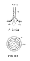
- Figs. 10A and 10B are views for explaining how the blood flows through the header when H/D is equal to 1.3.
- The present invention will be described in more detail with reference to the accompanying drawings.
- Fig. 1 shows an
artificial kidney 10 to which the present invention is applied. Thekidney 10 comprises a generally hollow cylindrical casing 11, in which abundle 13 ofhollow fibers 12 are housed. Thebundle 13 is held at its both end portions bypartition members partitions - The
partition members fiber bundle 13 such that opposite open ends of each hollow fiber open to the external end surfaces of themembers - Funnel-
like headers members headers portions partition members headers hollow fibers 12 at the opposite ends of the casing 11, respectively. - More specifically, as shown in Fig. 2, the
header 16 has afitting portion 16A of a large diameter having an inner surface 16AS, with the lower end 16AE of theportion 16A abutting against thepartition member 14 as shown in Fig. 1, and a frusto-conical portion 16B of a smaller diameter. The height h of thefitting portion 16A is, usually, 2 to 5 mm. Theportion 16B constitutes a blood inlet port 21 (see Fig.1), to which a blood circulation circuit is to be connected, and the blood from the blood circulation circuit is introduced therefrom to flow through the interior of eachhollow fiber 12. The inner diameter d of theportion 16B at the tip end thereof is, usually 3 to 5 mm. - Moreover, as seen from Fig. 2, the inner surface of the
header 16 is constituted by the inner surface 16AS of theportion 16A, atapered surface 16T continuous with the inner surface 16AS, and the frusto-conical inner surface 16BS of theportion 16B, with an intermediate radiusedsurface 16R having a radius of curvature r which connects thetapered surface 16T and the frusto-conical surface 16BS. - In accordance with the present invention, the ratio H/D is set at 0.8 to 1.2, where H denotes the distance or height of the
header 16 from the tip end of theportion 16B to the lower end 16AE of theportion 16A, and D denotes the inner diameter of theportion 16A. The inner diameter D is, usually, 25 to 60 mm. - In a more preferred embodiment, the gradient 0 of the
tapered surface 16T is set at 1 ° to 7°, more preferably 2.5 ° to 5 and most preferably about 3 and the vertical angle φ of the frusto-conical surface 16BS is preferably 18" to 22°. - Turning to Fig. 1, the
header 17 also has asimilar fitting portion 17A of a larger diameter, and a frusto-conical portion 17B of a smaller diameter. Theportion 17B constitutes ablood outlet port 22 for allowing blood which has passed through thehollow fibers 12 to return to the blood circulating circuit. It is not necessary to subject the structure of theheader 17 to the conditions set forth above with respect to to theheader 16, though theheader 17 may have the same structure as theheader 16. - Further, a dialyzing fluid inlet port 23 is provided at that connecting portion 11 A of the casing 11 which is located near the
partition member 15, and communicates with the space surrounding thehollow fibers 12 within the casing 11. A dialyzingfluid outlet port 24 is provided at that connecting portion 11 B of the casing 11 which is located near thepartition member 14, and communicates with the space surrounding the hollow fibers12. - That is, in the
artificial kidney 10, blood flows from theblood inlet port 21 to theblood outlet port 22, and the dialyzing fluid flows from the dialyzing fluid inlet port 23 to theoutlet 24. In this state, mass transfer occurs through thehollow fibers 12 each consisting of a semipermeable membrane. - The casing 11 and
headers - The
partition members - The
hollow fiber 12 is made of, e.g., regenerated cellulose in the case of an artificial kidney, while it is made of, e.g., polypropylene in the case of an artificial lung. The fiber, i.e., the semipermeable membrane has an inner diameter of approx. 200 µm, and a thickness of approx. 9 - 15 µm. Thebundle 13 consists of, for example, 500 - 15,000hollow fibers 12. Experiment 1 - The present inventor has conducted experiments to obtain an artificial kidney exhibiting a good blood treatment performance by preventing deflected flow or stay of the blood in the
header 16, thereby avoiding growth of a thrombus. The experiments were carried out by using an artificial kidney of a shape as shown in Fig. 1. Specifically, as shown in Fig. 2, the inner surface of theheader 16 consists of a taperedportion 16T extending from the inner surface 16AS of the large-diameterfitting portion 16A, an intermediate portion extending from the tapered portion and bent outwardly with a predetermined curvature, and a cylindrical portion 16S extending substantially straight from the intermediate portion. The inner diameter D of the large-diameter portion 16A and the distance H between the large-diameter portion 16A and small-diameter portion 16B were varied in the experiments. - A blood-circulation circuit was connected to the
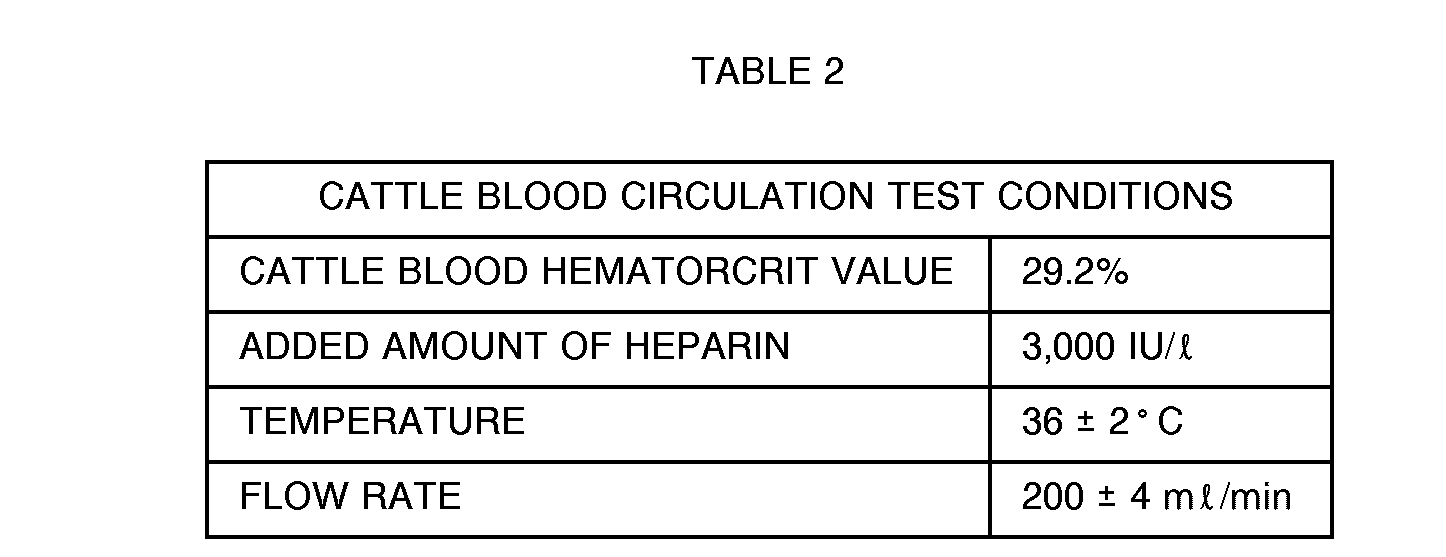
headers artificial kidney 10, as is shown in Fig. 3. In the figure,reference numeral 30 designates a pump, reference numeral 31 a cattle blood container, and reference numeral 32 a physiological saline solution container. - Circulation of cattle blood was performed using seven types of headers as shown in Table 1, and under the conditions shown in Table 2. The degree of growth of a thrombus in the
header 16 was measured.
- First, cattle blood was circulated for two hours through the blood-circulation circuit and a sample of the
artificial kidney 10, using a header No. 1 shown in Table 1, which had been filled with a physiological saline solution. Then, the cattle blood was returned to the container by means of the saline solution. - This was also done with headers No. 2 - No. 7 shown in Table 1, respectively. As a result, it was found that a white thrombus grew in the headers No. 1 and No. 7 (see Figs. 4 and 10).
- In light of the experiences so far, it is considered that a thrombus will grow after approx. two-hour circulation of cattle blood if there is a blood stay portion in the
header 16, and that a further thrombus will not grow even if the blood circulation is continued over five hours, since the activity of the blood is lost in this case. - The inventor obtained the following knowledge
- i) - iii) from the above experiments:
- i) As is shown in Fig. 4 directed to the case of H/D = 0.7, if H/D < 0.8, that route along the header height (particularly along the substantially straight portion 16S) which controls blood, introduced into the header, to flow in the axial direction thereof is relatively short. Thus, the blood cannot make a straight flow along the axis in the
header 16, i.e., the center of the flow will be deflected from the axis, which may cause ablood stay portion 100 along the inner periphery of the large-diameter portion 16A, thereby causing a thrombus. - ii) As is shown in Fig. 10 directed to the case of H/D = 1.3, if H/D > 1.2, that route along the header height (particularly along the substantially straight portion 16S) which controls blood, introduced into the header, to flow in the axial direction thereof is relatively long. Thus, the blood will make a long straight flow along the axis in the
header 16, resulting in that the flow of the blood at the center of the header is larger than that along the periphery thereof. Thus, ablood stay portion 100 may extend along the overall inner periphery of the large-diameter portion 16A, causing a thrombus. - iii) As is shown in Figs. 5 - 9 directed to the cases of H/D = 0.8, 0.9, 1.0, 1.1, and 1.2, respectively, if 0.8 < H/D 1.2, that route along the header height (particularly along the substantially straight portion 16S) which controls blood, introduced into the header, to flow in the axial direction thereof has an appropriate length (preferably, 0.9 ≦ H/D 1.1). Thus, the blood will form an appropriate straight flow along the axis in the
header 16, which does not cause deflected flow of the blood or stay thereof, being free from ablood stay portion 100, and hence a thrombus. Consequently, the header constructed as above provides a good blood treatment performance.
- i) As is shown in Fig. 4 directed to the case of H/D = 0.7, if H/D < 0.8, that route along the header height (particularly along the substantially straight portion 16S) which controls blood, introduced into the header, to flow in the axial direction thereof is relatively short. Thus, the blood cannot make a straight flow along the axis in the
- Further, the present inventor conducted similar experiments, by using the headers shown in Table 3 below. The cattle blood was flown under the condition specified in Table 4 below with the results shown in Table 5. The blood circulation time limit is the point at which the initial value of PBi (the pressure at the blood inlet side) is lowered by 50 mmHg.


- From the second experiments, the following knowledges iv) - vi) were obtained.
- iv) With <p of 18 to 22 degrees, the blood can flow along the frusto-conical inner surface of the
header 16 with uniform spreading toward the large opening into the hollow fibers. - v) With 0 of 1 to 7 degrees, the lineal speed of the blood at the peripheral portion can be increased, with the result that the blood can flow into the hollow fibers without lowering flow rate of the blood at the peripheral portion.
- vi) When the frusto-conical surface and the tapered
portion 16T are extrapolated by the radiusedportion 16R at the maximum radius of curvature r, the blood can flow more smoothly within theheader 16 without deflected flow or stay of flow of the blood. - As described above, the hollow fiber mass transfer apparatus of the invention can provide a good mass treatment performance by preventing deflected flow or stay of first mass introduced into the header, thereby preventing occurrence of any deposits.
Claims (3)
Applications Claiming Priority (4)
| Application Number | Priority Date | Filing Date | Title |
|---|---|---|---|
| JP2255056A JPH07102308B2 (en) | 1990-09-27 | 1990-09-27 | Hollow fiber type mass transfer device |
| JP255056/90 | 1990-09-27 | ||
| JP94858/91 | 1991-04-02 | ||
| JP9485891A JPH04305229A (en) | 1991-04-02 | 1991-04-02 | Hollow yarn type mass-transfer device |
Publications (2)
| Publication Number | Publication Date |
|---|---|
| EP0477966A1 true EP0477966A1 (en) | 1992-04-01 |
| EP0477966B1 EP0477966B1 (en) | 1995-12-06 |
Family
ID=26436098
Family Applications (1)
| Application Number | Title | Priority Date | Filing Date |
|---|---|---|---|
| EP91116538A Expired - Lifetime EP0477966B1 (en) | 1990-09-27 | 1991-09-27 | Hollow fiber mass transfer apparatus |
Country Status (2)
| Country | Link |
|---|---|
| EP (1) | EP0477966B1 (en) |
| DE (1) | DE69115204T2 (en) |
Cited By (4)
| Publication number | Priority date | Publication date | Assignee | Title |
|---|---|---|---|---|
| DE19714373C1 (en) * | 1997-04-08 | 1998-04-30 | Bio Lab Vertriebsgesellschaft | Mass exchange filter unit containing hollow fibre bundle for e.g. blood dialysis |
| WO1998045028A1 (en) * | 1997-04-08 | 1998-10-15 | Bio-Lab Vertriebsgesellschaft Mbh | Filter device with a flow guide in the closing cap |
| WO2010020384A1 (en) | 2008-08-22 | 2010-02-25 | Gambro Lundia Ab | Diffusion and/or filtration device |
| EP3431641A1 (en) | 2017-07-17 | 2019-01-23 | Maschinenfabrik Rieter AG | Cleaning device |
Citations (7)
| Publication number | Priority date | Publication date | Assignee | Title |
|---|---|---|---|---|
| US3882024A (en) * | 1974-04-19 | 1975-05-06 | Dow Chemical Co | Header for stagnation-sensitive liquids |
| EP0001736A1 (en) * | 1977-07-04 | 1979-05-16 | Terumo Corporation | An apparatus for dialysis of solution |
| DE3144552A1 (en) * | 1981-11-10 | 1983-05-19 | Sigdell, Jan-Erik, Dr., 4052 Basel | Flow-adapted dialyser cover |
| DE3144553A1 (en) * | 1981-11-10 | 1983-05-19 | Jan-Erik Dr. 4052 Basel Sigdell | Flow-adapted dialyser cover |
| EP0181470A2 (en) * | 1984-09-29 | 1986-05-21 | TERUMO KABUSHIKI KAISHA trading as TERUMO CORPORATION | Material transfer apparatus of hollow fiber type |
| EP0222032A1 (en) * | 1985-11-11 | 1987-05-20 | Senko Medical Instrument Mfg. Co., Ltd. | Blood oxygenator |
| DE3711695A1 (en) * | 1987-04-07 | 1988-10-27 | Akzo Gmbh | Distribution cap for a device for the extracorporal treatment of blood or its components |
-
1991
- 1991-09-27 DE DE69115204T patent/DE69115204T2/en not_active Expired - Fee Related
- 1991-09-27 EP EP91116538A patent/EP0477966B1/en not_active Expired - Lifetime
Patent Citations (7)
| Publication number | Priority date | Publication date | Assignee | Title |
|---|---|---|---|---|
| US3882024A (en) * | 1974-04-19 | 1975-05-06 | Dow Chemical Co | Header for stagnation-sensitive liquids |
| EP0001736A1 (en) * | 1977-07-04 | 1979-05-16 | Terumo Corporation | An apparatus for dialysis of solution |
| DE3144552A1 (en) * | 1981-11-10 | 1983-05-19 | Sigdell, Jan-Erik, Dr., 4052 Basel | Flow-adapted dialyser cover |
| DE3144553A1 (en) * | 1981-11-10 | 1983-05-19 | Jan-Erik Dr. 4052 Basel Sigdell | Flow-adapted dialyser cover |
| EP0181470A2 (en) * | 1984-09-29 | 1986-05-21 | TERUMO KABUSHIKI KAISHA trading as TERUMO CORPORATION | Material transfer apparatus of hollow fiber type |
| EP0222032A1 (en) * | 1985-11-11 | 1987-05-20 | Senko Medical Instrument Mfg. Co., Ltd. | Blood oxygenator |
| DE3711695A1 (en) * | 1987-04-07 | 1988-10-27 | Akzo Gmbh | Distribution cap for a device for the extracorporal treatment of blood or its components |
Cited By (4)
| Publication number | Priority date | Publication date | Assignee | Title |
|---|---|---|---|---|
| DE19714373C1 (en) * | 1997-04-08 | 1998-04-30 | Bio Lab Vertriebsgesellschaft | Mass exchange filter unit containing hollow fibre bundle for e.g. blood dialysis |
| WO1998045028A1 (en) * | 1997-04-08 | 1998-10-15 | Bio-Lab Vertriebsgesellschaft Mbh | Filter device with a flow guide in the closing cap |
| WO2010020384A1 (en) | 2008-08-22 | 2010-02-25 | Gambro Lundia Ab | Diffusion and/or filtration device |
| EP3431641A1 (en) | 2017-07-17 | 2019-01-23 | Maschinenfabrik Rieter AG | Cleaning device |
Also Published As
| Publication number | Publication date |
|---|---|
| DE69115204D1 (en) | 1996-01-18 |
| DE69115204T2 (en) | 1996-05-02 |
| EP0477966B1 (en) | 1995-12-06 |
Similar Documents
| Publication | Publication Date | Title |
|---|---|---|
| CA1158510A (en) | Hollow fiber-type artificial lung having enclosed heat exchanger | |
| US4861485A (en) | Hemodiafiltration device | |
| US7563376B2 (en) | Plasma purification membrane and plasma purification system | |
| EP0164025B1 (en) | Hollow fiber membrane type oxygenator and method for manufacturing same | |
| EP0044075B1 (en) | Fluid separation element | |
| EP1323462B1 (en) | Filtering device with associated sealing design and method | |
| US4125468A (en) | Hollow-fiber permeability apparatus | |
| EP0165478A1 (en) | A method of producing a device including a bundle of hollow fibers | |
| EP0890368A1 (en) | Blood treatment apparatus | |
| EP0167162B1 (en) | Hollow fiber type oxygenator | |
| US4231877A (en) | Blood dialyzer | |
| US7250108B2 (en) | Method for measuring the local hydraulic permeability of a sub-group of hollow fibre of a bundle of hollow fibres | |
| US5238561A (en) | Hollow fiber mass transfer apparatus | |
| EP0477966A1 (en) | Hollow fiber mass transfer apparatus | |
| WO1984001522A1 (en) | Filter | |
| EP0305672A1 (en) | A diffusion and/or filtration apparatus, a blank for the main part of the housing intended for said apparatus and a method of manufacturing the apparatus | |
| US4959149A (en) | Multiple tube series membrane filtration module and method of preparing same | |
| JPH04305229A (en) | Hollow yarn type mass-transfer device | |
| JPH04135628A (en) | Hollow-fiber type mass transfer device | |
| JP2000042100A (en) | Hollow fiber membrane type liquid treatment apparatus | |
| EP3473327A1 (en) | Integrated fluid treatment device, and process using such device | |
| JPH04284834A (en) | Manufacturing method of hollow fiber membrane module | |
| CA1254467A (en) | Hollow fiber type oxygenator | |
| JP3048652B2 (en) | Manufacturing method of membrane oxygenator | |
| JP2581558Y2 (en) | Blood processing module |
Legal Events
| Date | Code | Title | Description |
|---|---|---|---|
| PUAI | Public reference made under article 153(3) epc to a published international application that has entered the european phase |
Free format text: ORIGINAL CODE: 0009012 |
|
| 17P | Request for examination filed |
Effective date: 19910927 |
|
| AK | Designated contracting states |
Kind code of ref document: A1 Designated state(s): BE DE FR GB IT NL SE |
|
| 17Q | First examination report despatched |
Effective date: 19921113 |
|
| GRAA | (expected) grant |
Free format text: ORIGINAL CODE: 0009210 |
|
| ITF | It: translation for a ep patent filed | ||
| AK | Designated contracting states |
Kind code of ref document: B1 Designated state(s): BE DE FR GB IT NL SE |
|
| PG25 | Lapsed in a contracting state [announced via postgrant information from national office to epo] |
Ref country code: NL Free format text: LAPSE BECAUSE OF FAILURE TO SUBMIT A TRANSLATION OF THE DESCRIPTION OR TO PAY THE FEE WITHIN THE PRESCRIBED TIME-LIMIT Effective date: 19951206 Ref country code: BE Effective date: 19951206 |
|
| ET | Fr: translation filed | ||
| REF | Corresponds to: |
Ref document number: 69115204 Country of ref document: DE Date of ref document: 19960118 |
|
| PG25 | Lapsed in a contracting state [announced via postgrant information from national office to epo] |
Ref country code: SE Effective date: 19960306 |
|
| NLV1 | Nl: lapsed or annulled due to failure to fulfill the requirements of art. 29p and 29m of the patents act | ||
| PG25 | Lapsed in a contracting state [announced via postgrant information from national office to epo] |
Ref country code: GB Effective date: 19960927 |
|
| PLBE | No opposition filed within time limit |
Free format text: ORIGINAL CODE: 0009261 |
|
| STAA | Information on the status of an ep patent application or granted ep patent |
Free format text: STATUS: NO OPPOSITION FILED WITHIN TIME LIMIT |
|
| 26N | No opposition filed | ||
| GBPC | Gb: european patent ceased through non-payment of renewal fee |
Effective date: 19960927 |
|
| PG25 | Lapsed in a contracting state [announced via postgrant information from national office to epo] |
Ref country code: DE Effective date: 19970603 |
|
| PG25 | Lapsed in a contracting state [announced via postgrant information from national office to epo] |
Ref country code: FR Effective date: 19970630 |
|
| REG | Reference to a national code |
Ref country code: FR Ref legal event code: ST |
|
| REG | Reference to a national code |
Ref country code: FR Ref legal event code: ST |
|
| PG25 | Lapsed in a contracting state [announced via postgrant information from national office to epo] |
Ref country code: IT Free format text: LAPSE BECAUSE OF NON-PAYMENT OF DUE FEES;WARNING: LAPSES OF ITALIAN PATENTS WITH EFFECTIVE DATE BEFORE 2007 MAY HAVE OCCURRED AT ANY TIME BEFORE 2007. THE CORRECT EFFECTIVE DATE MAY BE DIFFERENT FROM THE ONE RECORDED. Effective date: 20050927 |