EP0477702B1 - Method for assembling a car - Google Patents
Method for assembling a car Download PDFInfo
- Publication number
- EP0477702B1 EP0477702B1 EP91115587A EP91115587A EP0477702B1 EP 0477702 B1 EP0477702 B1 EP 0477702B1 EP 91115587 A EP91115587 A EP 91115587A EP 91115587 A EP91115587 A EP 91115587A EP 0477702 B1 EP0477702 B1 EP 0477702B1
- Authority
- EP
- European Patent Office
- Prior art keywords
- car body
- shroud
- nose unit
- engagement
- shroud panel
- Prior art date
- Legal status (The legal status is an assumption and is not a legal conclusion. Google has not performed a legal analysis and makes no representation as to the accuracy of the status listed.)
- Expired - Lifetime
Links
- 238000000034 method Methods 0.000 title claims description 19
- 230000002787 reinforcement Effects 0.000 claims description 29
- 238000003466 welding Methods 0.000 claims description 7
- 238000003780 insertion Methods 0.000 description 11
- 230000037431 insertion Effects 0.000 description 11
- 239000011248 coating agent Substances 0.000 description 3
- 238000000576 coating method Methods 0.000 description 3
- 230000001105 regulatory effect Effects 0.000 description 2
- 239000000725 suspension Substances 0.000 description 2
Images






Classifications
-
- B—PERFORMING OPERATIONS; TRANSPORTING
- B62—LAND VEHICLES FOR TRAVELLING OTHERWISE THAN ON RAILS
- B62D—MOTOR VEHICLES; TRAILERS
- B62D65/00—Designing, manufacturing, e.g. assembling, facilitating disassembly, or structurally modifying motor vehicles or trailers, not otherwise provided for
- B62D65/02—Joining sub-units or components to, or positioning sub-units or components with respect to, body shell or other sub-units or components
- B62D65/04—Joining preassembled modular units composed of sub-units performing diverse functions, e.g. engine and bonnet
-
- Y—GENERAL TAGGING OF NEW TECHNOLOGICAL DEVELOPMENTS; GENERAL TAGGING OF CROSS-SECTIONAL TECHNOLOGIES SPANNING OVER SEVERAL SECTIONS OF THE IPC; TECHNICAL SUBJECTS COVERED BY FORMER USPC CROSS-REFERENCE ART COLLECTIONS [XRACs] AND DIGESTS
- Y10—TECHNICAL SUBJECTS COVERED BY FORMER USPC
- Y10T—TECHNICAL SUBJECTS COVERED BY FORMER US CLASSIFICATION
- Y10T29/00—Metal working
- Y10T29/49—Method of mechanical manufacture
- Y10T29/49826—Assembling or joining
- Y10T29/49828—Progressively advancing of work assembly station or assembled portion of work
- Y10T29/49829—Advancing work to successive stations [i.e., assembly line]
-
- Y—GENERAL TAGGING OF NEW TECHNOLOGICAL DEVELOPMENTS; GENERAL TAGGING OF CROSS-SECTIONAL TECHNOLOGIES SPANNING OVER SEVERAL SECTIONS OF THE IPC; TECHNICAL SUBJECTS COVERED BY FORMER USPC CROSS-REFERENCE ART COLLECTIONS [XRACs] AND DIGESTS
- Y10—TECHNICAL SUBJECTS COVERED BY FORMER USPC
- Y10T—TECHNICAL SUBJECTS COVERED BY FORMER US CLASSIFICATION
- Y10T29/00—Metal working
- Y10T29/49—Method of mechanical manufacture
- Y10T29/49826—Assembling or joining
- Y10T29/49828—Progressively advancing of work assembly station or assembled portion of work
- Y10T29/49831—Advancing station
Definitions
- the present invention relates to a method for assembling a car, and more particularly to a method for fixing a nose unit having a shroud panel to the front portion of a car body on a car assembly line.
- the car such as an automobile has been assembled by the flow line operation on the car assembly line.
- a bumper, a radiator, a cooler condenser and the like are sequentially attached to the front portion of the car body in individual attachment stations provided in the middle of the car assembly line. Accordingly, there is caused a problem that the number of working stations is increased on the car assembly line so that the car assembly line has its overall length increased and is complicated.
- Japanese Unexamined Patent Publication No. 63-103771 discloses a technique wherein parts such as a radiator, a head lamp, a bumper, a radiator grille and the like are attached to a radiator core support so as to be united. The unit thus obtained is separately assembled and fixed to the front portion of the car body so that the overall length of the car assembly line is controlled.
- the front portion of the car body is provided with wheel aprons for forming the side walls of an engine room.
- Front side frames and apron reinforcements are fixed to the underside and upside of the wheel aprons, respectively.
- a shroud panel is provided between the apron reinforcements.
- a cross member is provided between the front side frames.
- the shroud panel functions as a unit component.
- the cross member also functions as the unit component, if necessary.
- the parts such as the radiator and the like are incorporated in the unit components so that a nose unit can be formed. Before the nose unit is fixed to the car body, therefore, it is necessary to attach by welding or the like any member (for example, a bracket) for mounting the shroud panel to the car body when fixing the nose unit thereto.
- the above-mentioned members cannot independently and precisely be fixed in the predetermined positions of the car body because there are no means for defining, i.e., determining the positions in which the members are attached to the car body. If the nose unit is fixed to the car body, therefore, the adjustment of the parts on the nose unit and car body sides is damaged. Consequently, there is lowered the precision in attachment of the parts on the nose unit side to the car body. When the precision in attachment is lowered, the stiffness of the car body cannot be ensured, however, and there is also the possibility that a cap or the like is generated on the outer face of the car body.
- US-A-4 793 055 discloses a vehicle assembly line that includes a body assembly line having a door removing station for detaching at least one door from a vehicle body fed thereto with the door, and a door mounting station for attaching the door fed thereto to the vehicle body from which the door is detached at the door removing station, whereby a door subassembly line including a door equipping station is so located in the vicinity of the door mounting station that the door when detached from the vehicle body at the door removing station and equipped with various door parts at this door equipping station may be transported by a door conveying device from the door removing station to and through the door equipping station and from there to the door mounting station whereby the relative distances between the individual stations is chosen such as not to cause any interference between the overall body assembly line and this individual subassembly line for the vehicle doors.
- the fixing means for fixing the shroud panel to the car body is temporarily attached to the shroud panel before various parts are mounted on the shroud panel so as to assemble the nose unit.
- the fixing means is attached to the car body.
- the shroud panel is removed from the fixing means and the various parts are attached to the shroud panel so as to assemble the nose unit.
- the shroud panel of the nose unit is fastened to the fixing means so as to fix the nose unit to the car body.
- the fixing means is attached to the car body in consideration of the mounting of the various parts.
- the shroud panel is removed from the fixing means with being positioned by a positioning member.
- the fixing means has brackets to be welded to the car body, for example.
- the shroud panel has a shroud upper extended to both sides of the car body. Both end portions of the shroud upper are fastened to the brackets.
- the bracket has a base and an upper fastening portion.
- the base is welded to the wheel apron reinforcements, wheel apron and wheel apron gusset.
- the upper fastening portion is protruded from the base to the engine room side.
- the fixing means is mounted on the front portion of the car body with being temporarily attached to the shroud panel on the nose unit side. Consequently, the positional relationship between the fixing means and the shroud panel is precisely regulated, so that the fixing means can be mounted on the car body with high precision. Accordingly, the precision in mounting of the fixing means is enhanced.
- the shroud panel can be fastened to the fixing means with high precision when fixing the nose unit to the car body, so that the adjustment of the parts on the car body and nose unit sides can be ensured. Consequently, there can be obtained high precision in attachment.
- the suitable stiffness for the car body can be ensured. As a result, it is possible to prevent a gap or the like from being generated on the outer face of the car body owing to no adjustment.
- the apron reinforcements have engagement portions on the rearer side of the car body than the welding positions of the brackets.
- a bar is engaged with the engagement portions.
- the bar serves to prevent the front portion of the car body from being deformed when fixing the nose unit thereto.
- the engagement portions are fixed to the apron reinforcements so as to be protruded to the engine room side. Consequently, even if the front side frames are not connected to each other by the cross member, the stiffness of the front portion of the car body can be ensured.
- the nose unit can be fixed to the car body with high precision.
- the shroud panel includes a shroud upper and a stay.
- the shroud upper has first engagement means.
- the stay is extended downward from the shroud upper and has second engagement means.
- the lower portion of the stay is positioned by a positioning member so as to hold a normal position with respect to the shroud upper. In this state, various parts are attached to the shroud panel.
- the shroud panel includes shroud side panels.
- the shroud side panels are provided on both sides of the stay, are vertically extended downward from the shroud upper and have third engagement means.
- Radiator support brackets are fixed to the lower end portions of the shroud side panels. The radiator support brackets serve to support the lower portions of the radiator and cooler condenser as parts.
- the positioning member is a rectangular frame, and has engagement pins on its upper and lower portions respectively.
- the upper engagement pins are respectively engaged with the first engagement means of the shroud upper.
- the lower engagement pins are engaged respectively with the second and third engagement means of the lower end portions of the stay and shroud side panels.
- the shroud panel has a shroud upper, a stay and shroud side panels.
- the stay is extended downward from the shroud upper.
- the shroud side panels are provided on both sides of the stay and are vertically extended downward from the shroud upper.
- the cross member can be fixed to the lower end portions of the stay and shroud side panels.
- the side end portions of the cross member are fastened to the front side frames.
- the radiator support brackets are fixed to the cross member.
- the radiator support brackets serve to support the lower portion of the radiator as a part.
- the lower portion of the stay is fixed to the member on the car body side.
- the member on the car body side is a cross member which is provided between the tip portions of the front side frames, for example.
- the fixing means is mounted on the car body with the shroud panel temporarily fastened to the cross member in order to increase the precision in mounting of the fixing means.
- Fig. 1 shows a car body to which the present invention is applied.
- the car body is indicated at 1
- front fenders are indicated at 2
- an engine room is indicated at 3.
- wheel aprons forming the side walls of the engine room 3.
- Front side frames 5 and apron reinforcements 6 are respectively provided on the underside and upside of the wheel aprons 4.
- a cross member 7 is provided between the tip portions of the front side frames 5.
- the cross member 7 is extended to both sides of the car body 1.
- Wheel apron gussets 8 are fixed to the front side frames 5 and the cross member 7. They are precisely positioned and welded to one another on a first main line C to be described below.
- Shroud upper fixing brackets 11 are protruded to the engine room 3 side, i.e., the inside of the car body 1, and are welded to the front end portions of the apron reinforcements 6. Both end portions of a shroud panel 10 (shroud upper 10a) forming a nose unit 9 are fastened to the brackets 11.
- the bracket 11 has a base 11a welded to the wheel apron reinforcement 6, wheel apron 4 and wheel apron gusset 8.
- the base 11a has an upper fastening portion 11b protruded to the engine room 3 side.
- the upper fastening portion 11b has an almost L-shaped cross section.
- the upper fastening portion 11b has bolt insertion holes 12. Nuts (not shown) are fixed onto the lower face side of the upper fastening portion 11b corresponding to the bolt insertion holes 12.
- Engagement portions 13 are fixed to the apron reinforcements 6 so as to be protruded to the engine room 3 side in slightly rearer portions of the car body than the fixing positions of the brackets 11.
- the engagement portions 13 have engagement holes.
- the engagement portions 13 are provided for fixing a bar 14.
- the bar 14 serves to prevent the front portion of the car body from being deformed when fixing the nose unit thereto.
- the shroud panel 10 has the shroud upper 10a.
- the shroud upper 10a has an almost L-shaped cross section and is extended to both sides of the car body 1. Both end portions of the shroud upper 10a can be fitted in the brackets 11 and have bolt insertion holes (not shown) corresponding to the bolt insertion holes 12 on the brackets 11. Engagement holes 16 are formed at the inner positions of the bolt insertion holes 12. The engagement holes 16 are provided for attaching a nose unit fixing member 15.
- the upper end portion of a center stay 10b is fixed to the nearly center portion of the shroud upper 10a.
- the center stay 10b is vertically suspended.
- the upper end portions of shroud side panels 10c are fixed to both sides of the center stay 10b.
- the shroud side panels 10c are vertically suspended.
- Radiator support brackets 17 are fixed to the lower end portions of the shroud side panels 10c.
- a radiator 21, a cooler condenser 22, a bumper reinforcement 23 and a bumper 24 are attached to the shroud panel 10.
- Pins 25 are engaged with the radiator support brackets 17 provided on the shroud panel 10.
- the pins 25 are protruded from the lower end portion of the radiator 21.
- the upper end portion of the radiator 21 is attached to the shroud upper 10a through connecting members 26 (see Fig. 2).
- Pins 27 are engaged with the radiator support brackets 17.
- the pins 27 are protruded from the lower end portion of the cooler condenser 22.
- the upper end portion of the cooler condenser 22 is atached to the shroud upper 10a through connecting members 28.
- a bumper reinforcement 23 and a bumper 24 are fastened to the shroud side panels 10c through bolts 34 and nuts (not shown) by using the openings formed on the shroud side panels 10c.
- the bolts 34 are protruded from the bumper reinforcement 23.
- Fig. 4 shows only the main parts forming the nose unit 9. Other parts such as a cooler receiver tank, a bonnet lock and the like are attached to the shroud panel 10.
- Fig. 5 parts are sent out of a car body, temporary attachment line, and a frame attachment line and are connected to each other on a first main line C.
- Each portion of the car body is subjected to a predetermined welding along the first main line C. Consequently, the car body 1 can be formed as shown in Fig. 1.
- Fig. 1 the structure of the front portion of the car body 1 is clearly displayed by the absence of the shroud panel 10.
- the car body 1 is delivered into a coating line D.
- the car body 1 when coated is subjected to predetermined steps such as a suspension attachment and the like on a second main line E.
- the ready mounted car is transmitted in the direction of an arrow F.
- Both end portions of the shroud upper 10a are fitted on the upper fastening portions 11b of the brackets 11 from above on the car body temporary attachment line.
- Fastening bolts 29 are inserted into bolt insertion holes (not shown) on the shroud upper 10a and into the bolt insertion holes 12 of the brackets 11, and then are engaged with nuts welded to the lower face of the brackets 11. Consequently, the brackets 11 are temporarily attached to the shroud panel 10.
- the brackets 11 are applied to the front end portions of the apron reinforcements 6.
- the lower end portions of the center stay 10b and the shroud side panels 10c are temporarily attached to the cross member 7 through fastening bolts 30 (Fig.3).
- the radiator support brackets 17 are engaged with and seated on the upside of the cross member 7.
- the shroud panel 10 will then be positioned.
- the temporary attachment is carried out through the fastening bolts 30 in a state where the bar 14 is provided between the engagement portions 13 on the apron reinforcements 6 so as to prevent the side walls forming both sides of the engine room 3 from being expanded.
- the base 11a of the bracket 11 is fixed to the upper face 6a of the apron reinforcement 6 and the side face of the wheel apron 4.
- the wheel apron 4 is provided on the engine room 3 side of the apron reinforcement 6.
- the wheel apron gusset 8 is fixed to the front side frame 5 and the cross member 7 side, and has a flange 8a extended upward.
- the flange 8a is inserted into and welded to the base 11a of the bracket 11.
- a flange 4a of the wheel apron 4 on the front side of the car body 1 is welded to the flange 8a. Accordingly, the wheel apron 4, apron reinforcement 6 and wheel apron gusset 8 are welded to one another.
- the bracket 11 is fixed to the wheel apron 4, apron reinforcement 6 and wheel apron gusset 8.
- brackets 11 are temporarily attached to the shroud panel 10 and the shroud panel 10 is temporarily fastened to the cross member 7, the brackets 11 are welded to the car body 1. Then, the car body 1 is delivered along the coating line D. After the car body 1 gets out of the coating line D, the shroud panel 10 is removed from the car body 1 in a station S1 which is provided on the inlet of the second main line E.
- the shroud panel 10 is removed from the car body 1 by using the nose unit fixing member 15 shown in Fig. 4.
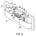
- the nose unit fixing member 15 is a rectangular frame, and has engagement pins 31 and a support portion 15a on its upper and lower portions.
- the engagement pins 31 are engaged with the engagement holes 16 formed on the shroud upper 10a.
- the support portion 15a receives and supports the shroud upper 10a, and has engagement pins 32.
- the engagement pins 32 are engaged with engagement portions 33.
- the engagement portions 33 are provided on the lower end portions of the center stay 10b and the shroud side panels 10c of the shroud panel 10.
- the engagement pins 31 and 32 are engaged with the engagement holes 16 and engagement portions 33 respectively, so that the shroud panel 10 is held by the nose unit fixing member 15. In this state, the shroud upper 10a is released from the brackets 11, and the center stay 10b and the shroud side panels 10c are released from the cross member 7.
- the shroud panel 10 is then removed from the car body 1 and is held by the nose unit fixing member 15.
- various parts such as the radiator 21, the cooler condenser 22, the bumper reinforcement 23, the bumper 24 and the like are then attached to the shroud panel 10 so as to assemble the nose unit 9 on a nose unit assembly line G.
- the various parts are attached to the shroud panel 10 held by the nose unit fixing member 15 such that the center stay 10b and the shroud side panels 10c are precisely positioned with respect to the shroud upper 10a.
- At 10g are indicated bolt insertion holes for attaching the radiator 21 to the shroud panel 10
- at 34a are indicated bolts for fastening the bumper reinforcement 23 to the shroud side panels 10c
- at 34b are indicated bolts for fastening the bumper reinforcement 23 to bolt insertion holes 36 on cross member sides 35.
- the nose unit 9 thus assembled is transmitted to a nose unit fixing station S2 shown in Fig. 5.
- the car body 1 is delivered along the second main line E, and is subjected to necessary working for attaching various parts such as a suspension and the like.
- the nose unit 9 is fixed to the car body 1 in the nose unit fixing station S2 provided in the middle of the second main line E.
- the nose unit fixing member 15 is returned to the shroud panel removing station S1 along a member return line H.
- the nose unit 9 is fixed to the car body 1. More specifically, the shroud upper 10a is fastened to the brackets 11 through the bolts 29 (see Fig. 7).
- the shroud side panels 10c are fastened to the cross member 7 through bolts 30 with the radiator support brackets 17 engaged with the cross member 7.
- the bumper reinforcement 23 is fastened to the wheel apron gussets 8 through the bolts 34 by using the bolt insertion holes 36 on the cross member sides 35.
- the cross member sides 35 are integrated with the wheel apron gussets 8. Then, there are attached to the car body 1 other parts such as a radiator grille, a head lamp and the like (not shown).
- the shroud upper 10a of the shroud panel 10 forming the nose unit 9 is temporarily attached to the brackets 11 through the bolts 29. Then, the brackets 11 are welded to the car body 1 with the shroud panel 10 temporarily attached to the cross member 7 through the bolts 30. Consequently, the brackets 11 are precisely positioned and welded to the car body 1.
- welding is carried out with the positional relationship between the brackets 11 and the shroud panel 10 (and nose unit 9) regulated, so that the precision in welding is improved. Accordingly, there can be enhanced the precision in fixation of the nose unit 9 to the car body 1. Consequently, the stiffness of the car body can be increased. In addition, it is possible to prevent a gap of the like from being generated on the outer face of the car body 1.
- the present invention can also be applied to a car assembly line shown in Fig. 8.
- a car body 1 is assembled along a line K by predetermined delivery means 51.
- the car body 1 thus assembled is delivered to the nose unit assembly station L by a delivery conveyer 52.
- a nose unit 9 is assembled in a nose unit assembly station L while the car body 1 is delivered by the delivery conveyer 52.
- the nose unit 9 is transferred along a predetermined passage M by transfer means 53 such as a truck.
- the nose unit 9 is fixed to the car body 1.
- the car body 1 having the nose unit 9 changes in course by a turntable 54, and is received by the predetermined delivery means 51 through a delivery conveyer 55.
- the car body 1 is delivered along a line N again, and then assembly is carried out.
- the car body 1 is delivered to the nose unit assembly station L as follows. While the car body 1 is delivered along the car assembly line, wheel aprons 4 are attached to the inside of front fenders 2. The wheel aprons 4 form the inside faces of the engine room 3.
- a pair of front side frames 5 are provided on the underside of the wheel aprons 4.
- the front side frames 5 are extended in the longitudinal direction of the car body 1 and take the form of a closed cross section.
- apron reinforcements 6 (one of them is shown) are provided on the upside of the wheel aprons 4.
- the apron reinforcements 6 are extended in the longitudinal direction of the car body 1.
- a cross member 7 is provided between the tip portions of the front side frames 5.
- the cross member 7 is extended in the direction of a car width and takes the form of the closed cross section.
- Wheel apron gussets 8 are provided from the junctions of the front side frames 5 and cross member 7 to the front end portions of the front wheel aprons 4. They are precisely positioned, and are welded and integrated with one another.
- FIG. 9 at 10h are indicated bolt insertion holes for fastening end portions 10i of a shroud upper 10a to nose unit fixing brackets 11A.
- the nose unit 9 is assembled in the nose unit assembly station L by attaching various parts such as a radiator and the like to be mounted on the front portion of the car body 1.
- the nose unit 9 thus assembled is fastened to the brackets 11A of the car body 1.
- the various parts are attached to the nose unit 9 with the shroud upper 10a held by fixing member 15.
- the nose unit 9 having the various parts is fixed to the car body 1.
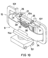
- the nose unit 9 thus assembled is delivered along the delivery passage M by the truck 53 as delivery means (see Figs. 9 and 10).
- the truck 53 is provided below the fixing member 15.
- the nose unit 9 is then fixed to the car body.
- the shroud upper 10a and the lower portions of the center stay 10b and the shroud side panels 10c are positioned by the fixing member 15.
- the center stay 10b and the shroud side panels 10c are normally positioned on the shroud upper 10a with high precision. Accordingly, the various parts such as the radiator and the like are provided in normal positions of a unit base with high precision.
- the nose unit 9 can be formed with high precision by the unit base.
- the various parts such as the radiator and the like are normally positioned with high precision, particularly, the lower portions of the center stay 10b and the shroud side panels 10c are fastened through bolts to the front face of the cross member 7 on the car body 1 side. Consequently, the various parts such as the radiator and the like can be attached to the car body 1 with high precision.
- the nose unit 9 formed by the unit base including the various parts such as the radiator and the like there can be fixed to the car body 1 with high precision the nose unit 9 formed by the unit base including the various parts such as the radiator and the like.
- the cross member 7 connecting the front side frames 5 is fixed to the front portion of the car body 1.
- the cross member can be incorporated as a unit component on the nose unit.
- the basic structure is the same as in the above-mentioned embodiment. The same components are therefore represented by the same reference numerals, and their detailed description will be omitted.
- extended portions 5a are protruded downward from front side frames 5. Both end portions of a cross member 7A are fastened and fixed between the front side frames 5 by the extended portions 5a. Side end portions 7a of the cross member 7A on the nose unit 9A side are fastened to the car body 1 by inserting bolts 41 into holes 5b of the extended portions 5a. The side end portions 7a have nuts welded to their inner faces.
- the upper face portion of the cross member 7A is fastened through bolts 42 to the lower face portions of the front side frames 5.
- the lower face portions of the front side frames 5 have nuts welded to their inner faces.
- the lower face portion of the cross member 7A has holes 7b for the bolts 42 so as to be fastened to the lower face portions of the front side frames 5.
- the cross member 7A is fixed to the lower end portion of a shroud panel 10A, i.e., the lower end portions of the center stay 10e and the shroud side panels 10f.
- the center stay 10e has its upper end portions fixed to the shroud upper 10d.
- Radiator support brackets 43 are fixed to the rear side of the cross member 7A. The radiator support brackets 43 support the lower end portion of the radiator 21.
- the side end portions of the shroud upper 10d are fastened through bolts 44 to the underside of fastening portions 11c of shroud upper fixing brackets 11A.
Landscapes
- Engineering & Computer Science (AREA)
- Manufacturing & Machinery (AREA)
- Chemical & Material Sciences (AREA)
- Combustion & Propulsion (AREA)
- Transportation (AREA)
- Mechanical Engineering (AREA)
- Body Structure For Vehicles (AREA)
Description
- The present invention relates to a method for assembling a car, and more particularly to a method for fixing a nose unit having a shroud panel to the front portion of a car body on a car assembly line.
- Conventionally, the car such as an automobile has been assembled by the flow line operation on the car assembly line. A bumper, a radiator, a cooler condenser and the like are sequentially attached to the front portion of the car body in individual attachment stations provided in the middle of the car assembly line. Accordingly, there is caused a problem that the number of working stations is increased on the car assembly line so that the car assembly line has its overall length increased and is complicated.
- Japanese Unexamined Patent Publication No. 63-103771 discloses a technique wherein parts such as a radiator, a head lamp, a bumper, a radiator grille and the like are attached to a radiator core support so as to be united. The unit thus obtained is separately assembled and fixed to the front portion of the car body so that the overall length of the car assembly line is controlled.
- The front portion of the car body is provided with wheel aprons for forming the side walls of an engine room. Front side frames and apron reinforcements are fixed to the underside and upside of the wheel aprons, respectively. A shroud panel is provided between the apron reinforcements. A cross member is provided between the front side frames. In the case where the parts to be fixed to the front portion of the car body are to be united, the shroud panel functions as a unit component. In addition, the cross member also functions as the unit component, if necessary. The parts such as the radiator and the like are incorporated in the unit components so that a nose unit can be formed. Before the nose unit is fixed to the car body, therefore, it is necessary to attach by welding or the like any member (for example, a bracket) for mounting the shroud panel to the car body when fixing the nose unit thereto.
- However, the above-mentioned members cannot independently and precisely be fixed in the predetermined positions of the car body because there are no means for defining, i.e., determining the positions in which the members are attached to the car body. If the nose unit is fixed to the car body, therefore, the adjustment of the parts on the nose unit and car body sides is damaged. Consequently, there is lowered the precision in attachment of the parts on the nose unit side to the car body. When the precision in attachment is lowered, the stiffness of the car body cannot be ensured, however, and there is also the possibility that a cap or the like is generated on the outer face of the car body.
- US-A-4 793 055 discloses a vehicle assembly line that includes a body assembly line having a door removing station for detaching at least one door from a vehicle body fed thereto with the door, and a door mounting station for attaching the door fed thereto to the vehicle body from which the door is detached at the door removing station, whereby a door subassembly line including a door equipping station is so located in the vicinity of the door mounting station that the door when detached from the vehicle body at the door removing station and equipped with various door parts at this door equipping station may be transported by a door conveying device from the door removing station to and through the door equipping station and from there to the door mounting station whereby the relative distances between the individual stations is chosen such as not to cause any interference between the overall body assembly line and this individual subassembly line for the vehicle doors.
- It is an object of the present invention to provide a method for assembling a car wherein a nose unit is formed by separately uniting parts to be attached to the front portion of the car body, the nose unit is fixed to the car body, and there can be improved the precision in attachment of fixing means for fixing the nose unit (specifically, a shroud panel) to the car body and the precision in fixation of the nose unit. It is another object of the present invention to provide a method for fixing the nose unit having the shroud panel to the car body which is to be delivered along a car assembly line and has wheel apron reinforcements, wheel aprons, wheel apron gussets and front side frames in its front portion forming an engine room.
- To achieve the above-mentioned objects, the fixing means for fixing the shroud panel to the car body is temporarily attached to the shroud panel before various parts are mounted on the shroud panel so as to assemble the nose unit. In this state, the fixing means is attached to the car body. Then, the shroud panel is removed from the fixing means and the various parts are attached to the shroud panel so as to assemble the nose unit. The shroud panel of the nose unit is fastened to the fixing means so as to fix the nose unit to the car body. In this case, the fixing means is attached to the car body in consideration of the mounting of the various parts. Then, the shroud panel is removed from the fixing means with being positioned by a positioning member. The fixing means has brackets to be welded to the car body, for example. The shroud panel has a shroud upper extended to both sides of the car body. Both end portions of the shroud upper are fastened to the brackets. In that case, the bracket has a base and an upper fastening portion. The base is welded to the wheel apron reinforcements, wheel apron and wheel apron gusset. The upper fastening portion is protruded from the base to the engine room side.
- The fixing means is mounted on the front portion of the car body with being temporarily attached to the shroud panel on the nose unit side. Consequently, the positional relationship between the fixing means and the shroud panel is precisely regulated, so that the fixing means can be mounted on the car body with high precision. Accordingly, the precision in mounting of the fixing means is enhanced. Thus, the shroud panel can be fastened to the fixing means with high precision when fixing the nose unit to the car body, so that the adjustment of the parts on the car body and nose unit sides can be ensured. Consequently, there can be obtained high precision in attachment. In addition, the suitable stiffness for the car body can be ensured. As a result, it is possible to prevent a gap or the like from being generated on the outer face of the car body owing to no adjustment.
- The apron reinforcements have engagement portions on the rearer side of the car body than the welding positions of the brackets. A bar is engaged with the engagement portions. The bar serves to prevent the front portion of the car body from being deformed when fixing the nose unit thereto. The engagement portions are fixed to the apron reinforcements so as to be protruded to the engine room side. Consequently, even if the front side frames are not connected to each other by the cross member, the stiffness of the front portion of the car body can be ensured. Thus, the nose unit can be fixed to the car body with high precision.
- The shroud panel includes a shroud upper and a stay. The shroud upper has first engagement means. The stay is extended downward from the shroud upper and has second engagement means. The lower portion of the stay is positioned by a positioning member so as to hold a normal position with respect to the shroud upper. In this state, various parts are attached to the shroud panel. In addition, the shroud panel includes shroud side panels. The shroud side panels are provided on both sides of the stay, are vertically extended downward from the shroud upper and have third engagement means. Radiator support brackets are fixed to the lower end portions of the shroud side panels. The radiator support brackets serve to support the lower portions of the radiator and cooler condenser as parts.
- The positioning member is a rectangular frame, and has engagement pins on its upper and lower portions respectively. The upper engagement pins are respectively engaged with the first engagement means of the shroud upper. The lower engagement pins are engaged respectively with the second and third engagement means of the lower end portions of the stay and shroud side panels.
- The shroud panel has a shroud upper, a stay and shroud side panels. The stay is extended downward from the shroud upper. The shroud side panels are provided on both sides of the stay and are vertically extended downward from the shroud upper. The cross member can be fixed to the lower end portions of the stay and shroud side panels. The side end portions of the cross member are fastened to the front side frames. In this case, the radiator support brackets are fixed to the cross member. The radiator support brackets serve to support the lower portion of the radiator as a part.
- In the state where the various parts are attached and positioned by the positioning member, the lower portion of the stay is fixed to the member on the car body side. The member on the car body side is a cross member which is provided between the tip portions of the front side frames, for example.
- In the case where the car body has the cross member extended to its both sides and provided between the front side frames, the fixing means is mounted on the car body with the shroud panel temporarily fastened to the cross member in order to increase the precision in mounting of the fixing means.
- These and other objects, features and advantages of the present invention will become more apparent from the following detailed description and the drawings.
-
- Figure 1 is a perspective view of the front portion of a car body before fixing a nose unit thereto;
- Figure 2 is an enlarged perspective view of the shroud upper fastening portion of the nose unit;
- Figure 3 is a perspective view of the front portion of the car body to which the shroud panel is temporarily attached;
- Figure 4 is an exploded view of the nose unit;
- Figure 5 is a schematic view of a car assembly line;
- Figure 6 is an erection view of the nose unit;
- Figure 7 is a perspective view of the front portion of the car body to which the nose unit is fixed;
- Figure 8 is a view showing another embodiment of the present invention correspondingly to Figure 5;
- Figure 9 is a view showing the embodiment of the present invention correspondingly to Figure 4;
- Figure 10 is a view showing the embodiment of the present invention correspondingly to Figure 6;
- Figure 11 is a view showing yet another embodiment of the present invention corresponding to Figure 1;
- Figure 12 is a view showing the embodiment of the present invention corresponding to Figure 3;
- Figure 13 is a view showing to the embodiment of the present invention corresponding to Figure 4; and
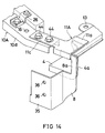
- Figure 14 is a view showing the embodiment of the present invention corresponding to Figure 2.
- Fig. 1 shows a car body to which the present invention is applied. In Fig. 1, the car body is indicated at 1, front fenders are indicated at 2, and an engine room is indicated at 3. At 4 are indicated wheel aprons forming the side walls of the engine room 3. Front side frames 5 and
apron reinforcements 6 are respectively provided on the underside and upside of thewheel aprons 4. A cross member 7 is provided between the tip portions of the front side frames 5. The cross member 7 is extended to both sides of thecar body 1.Wheel apron gussets 8 are fixed to the front side frames 5 and the cross member 7. They are precisely positioned and welded to one another on a first main line C to be described below. - Shroud upper fixing
brackets 11 are protruded to the engine room 3 side, i.e., the inside of thecar body 1, and are welded to the front end portions of theapron reinforcements 6. Both end portions of a shroud panel 10 (shroud upper 10a) forming anose unit 9 are fastened to thebrackets 11. - As shown in Fig. 2, the
bracket 11 has abase 11a welded to thewheel apron reinforcement 6,wheel apron 4 andwheel apron gusset 8. Thebase 11a has anupper fastening portion 11b protruded to the engine room 3 side. Theupper fastening portion 11b has an almost L-shaped cross section. Theupper fastening portion 11b has bolt insertion holes 12. Nuts (not shown) are fixed onto the lower face side of theupper fastening portion 11b corresponding to the bolt insertion holes 12. -
Engagement portions 13 are fixed to theapron reinforcements 6 so as to be protruded to the engine room 3 side in slightly rearer portions of the car body than the fixing positions of thebrackets 11. Theengagement portions 13 have engagement holes. Theengagement portions 13 are provided for fixing abar 14. Thebar 14 serves to prevent the front portion of the car body from being deformed when fixing the nose unit thereto. - As shown in Fig. 3, the
shroud panel 10 has the shroud upper 10a. The shroud upper 10a has an almost L-shaped cross section and is extended to both sides of thecar body 1. Both end portions of the shroud upper 10a can be fitted in thebrackets 11 and have bolt insertion holes (not shown) corresponding to the bolt insertion holes 12 on thebrackets 11. Engagement holes 16 are formed at the inner positions of the bolt insertion holes 12. The engagement holes 16 are provided for attaching a noseunit fixing member 15. The upper end portion of acenter stay 10b is fixed to the nearly center portion of the shroud upper 10a. Thecenter stay 10b is vertically suspended. The upper end portions ofshroud side panels 10c are fixed to both sides of thecenter stay 10b. Theshroud side panels 10c are vertically suspended.Radiator support brackets 17 are fixed to the lower end portions of theshroud side panels 10c. - As shown in Fig. 4, a
radiator 21, acooler condenser 22, abumper reinforcement 23 and abumper 24 are attached to theshroud panel 10.Pins 25 are engaged with theradiator support brackets 17 provided on theshroud panel 10. Thepins 25 are protruded from the lower end portion of theradiator 21. The upper end portion of theradiator 21 is attached to the shroud upper 10a through connecting members 26 (see Fig. 2).Pins 27 are engaged with theradiator support brackets 17. Thepins 27 are protruded from the lower end portion of thecooler condenser 22. the upper end portion of thecooler condenser 22 is atached to the shroud upper 10a through connectingmembers 28. Abumper reinforcement 23 and abumper 24 are fastened to theshroud side panels 10c through bolts 34 and nuts (not shown) by using the openings formed on theshroud side panels 10c. The bolts 34 are protruded from thebumper reinforcement 23. Fig. 4 shows only the main parts forming thenose unit 9. Other parts such as a cooler receiver tank, a bonnet lock and the like are attached to theshroud panel 10. - There will be described the method for assembling a car.
- As shown in Fig. 5, parts are sent out of a car body, temporary attachment line, and a frame attachment line and are connected to each other on a first main line C. Each portion of the car body is subjected to a predetermined welding along the first main line C. Consequently, the
car body 1 can be formed as shown in Fig. 1. In Fig. 1, the structure of the front portion of thecar body 1 is clearly displayed by the absence of theshroud panel 10. - The
car body 1 is delivered into a coating line D. Thecar body 1 when coated is subjected to predetermined steps such as a suspension attachment and the like on a second main line E. The ready mounted car is transmitted in the direction of an arrow F. - Both end portions of the shroud upper 10a are fitted on the
upper fastening portions 11b of thebrackets 11 from above on the car body temporary attachment line. Fasteningbolts 29 are inserted into bolt insertion holes (not shown) on the shroud upper 10a and into the bolt insertion holes 12 of thebrackets 11, and then are engaged with nuts welded to the lower face of thebrackets 11. Consequently, thebrackets 11 are temporarily attached to theshroud panel 10. - In that state, the
brackets 11 are applied to the front end portions of theapron reinforcements 6. At this time, the lower end portions of thecenter stay 10b and theshroud side panels 10c are temporarily attached to the cross member 7 through fastening bolts 30 (Fig.3). Theradiator support brackets 17 are engaged with and seated on the upside of the cross member 7. Theshroud panel 10 will then be positioned. The temporary attachment is carried out through the fastening bolts 30 in a state where thebar 14 is provided between theengagement portions 13 on theapron reinforcements 6 so as to prevent the side walls forming both sides of the engine room 3 from being expanded. - In the state of temporary attachment, the respective spaces between the
apron reinforcements 6 and between the front side frames 5 are controlled to become constant by the shroud upper 10a and the cross member 7. In addition, thewheel aprons 4 are also positioned. In this state, each portion of thecar body 1 is subjected to welding. Thebrackets 11 are also welded to thecar body 1. - Thus, the
base 11a of thebracket 11 is fixed to theupper face 6a of theapron reinforcement 6 and the side face of thewheel apron 4. Thewheel apron 4 is provided on the engine room 3 side of theapron reinforcement 6. - The
wheel apron gusset 8 is fixed to thefront side frame 5 and the cross member 7 side, and has aflange 8a extended upward. Theflange 8a is inserted into and welded to thebase 11a of thebracket 11. In addition, aflange 4a of thewheel apron 4 on the front side of thecar body 1 is welded to theflange 8a. Accordingly, thewheel apron 4,apron reinforcement 6 andwheel apron gusset 8 are welded to one another. Thebracket 11 is fixed to thewheel apron 4,apron reinforcement 6 andwheel apron gusset 8. - In the state where the
brackets 11 are temporarily attached to theshroud panel 10 and theshroud panel 10 is temporarily fastened to the cross member 7, thebrackets 11 are welded to thecar body 1. Then, thecar body 1 is delivered along the coating line D. After thecar body 1 gets out of the coating line D, theshroud panel 10 is removed from thecar body 1 in a station S1 which is provided on the inlet of the second main line E. - In order to assemble the nose unit, the
shroud panel 10 is removed from thecar body 1 by using the noseunit fixing member 15 shown in Fig. 4. - The nose
unit fixing member 15 is a rectangular frame, and has engagement pins 31 and asupport portion 15a on its upper and lower portions. The engagement pins 31 are engaged with the engagement holes 16 formed on the shroud upper 10a. Thesupport portion 15a receives and supports the shroud upper 10a, and has engagement pins 32. The engagement pins 32 are engaged withengagement portions 33. Theengagement portions 33 are provided on the lower end portions of thecenter stay 10b and theshroud side panels 10c of theshroud panel 10. - The engagement pins 31 and 32 are engaged with the engagement holes 16 and
engagement portions 33 respectively, so that theshroud panel 10 is held by the noseunit fixing member 15. In this state, the shroud upper 10a is released from thebrackets 11, and thecenter stay 10b and theshroud side panels 10c are released from the cross member 7. - The
shroud panel 10 is then removed from thecar body 1 and is held by the noseunit fixing member 15. As shown in Fig. 1, various parts such as theradiator 21, thecooler condenser 22, thebumper reinforcement 23, thebumper 24 and the like are then attached to theshroud panel 10 so as to assemble thenose unit 9 on a nose unit assembly line G. The various parts are attached to theshroud panel 10 held by the noseunit fixing member 15 such that thecenter stay 10b and theshroud side panels 10c are precisely positioned with respect to the shroud upper 10a. In Fig. 4, at 10g are indicated bolt insertion holes for attaching theradiator 21 to theshroud panel 10, at 34a are indicated bolts for fastening thebumper reinforcement 23 to theshroud side panels 10c, and at 34b are indicated bolts for fastening thebumper reinforcement 23 to bolt insertion holes 36 on cross member sides 35. - The
nose unit 9 thus assembled is transmitted to a nose unit fixing station S2 shown in Fig. 5. On the other hand, thecar body 1 is delivered along the second main line E, and is subjected to necessary working for attaching various parts such as a suspension and the like. Thenose unit 9 is fixed to thecar body 1 in the nose unit fixing station S2 provided in the middle of the second main line E. The noseunit fixing member 15 is returned to the shroud panel removing station S1 along a member return line H. - Similar to the temporary attachment shown in Fig. 3, the
nose unit 9 is fixed to thecar body 1. More specifically, the shroud upper 10a is fastened to thebrackets 11 through the bolts 29 (see Fig. 7). Theshroud side panels 10c are fastened to the cross member 7 through bolts 30 with theradiator support brackets 17 engaged with the cross member 7. Thebumper reinforcement 23 is fastened to thewheel apron gussets 8 through the bolts 34 by using the bolt insertion holes 36 on the cross member sides 35. The cross member sides 35 are integrated with thewheel apron gussets 8. Then, there are attached to thecar body 1 other parts such as a radiator grille, a head lamp and the like (not shown). - With the above-mentioned structure, the shroud upper 10a of the
shroud panel 10 forming thenose unit 9 is temporarily attached to thebrackets 11 through thebolts 29. Then, thebrackets 11 are welded to thecar body 1 with theshroud panel 10 temporarily attached to the cross member 7 through the bolts 30. Consequently, thebrackets 11 are precisely positioned and welded to thecar body 1. In addition, welding is carried out with the positional relationship between thebrackets 11 and the shroud panel 10 (and nose unit 9) regulated, so that the precision in welding is improved. Accordingly, there can be enhanced the precision in fixation of thenose unit 9 to thecar body 1. Consequently, the stiffness of the car body can be increased. In addition, it is possible to prevent a gap of the like from being generated on the outer face of thecar body 1. - The present invention can also be applied to a car assembly line shown in Fig. 8.
- A
car body 1 is assembled along a line K by predetermined delivery means 51. Thecar body 1 thus assembled is delivered to the nose unit assembly station L by adelivery conveyer 52. Anose unit 9 is assembled in a nose unit assembly station L while thecar body 1 is delivered by thedelivery conveyer 52. Thenose unit 9 is transferred along a predetermined passage M by transfer means 53 such as a truck. Then, thenose unit 9 is fixed to thecar body 1. Thereafter, thecar body 1 having thenose unit 9 changes in course by aturntable 54, and is received by the predetermined delivery means 51 through adelivery conveyer 55. Thecar body 1 is delivered along a line N again, and then assembly is carried out. - The
car body 1 is delivered to the nose unit assembly station L as follows. While thecar body 1 is delivered along the car assembly line,wheel aprons 4 are attached to the inside offront fenders 2. Thewheel aprons 4 form the inside faces of the engine room 3. In addition, a pair of front side frames 5 are provided on the underside of thewheel aprons 4. The front side frames 5 are extended in the longitudinal direction of thecar body 1 and take the form of a closed cross section. Furthermore, apron reinforcements 6 (one of them is shown) are provided on the upside of thewheel aprons 4. Theapron reinforcements 6 are extended in the longitudinal direction of thecar body 1. A cross member 7 is provided between the tip portions of the front side frames 5. The cross member 7 is extended in the direction of a car width and takes the form of the closed cross section.Wheel apron gussets 8 are provided from the junctions of the front side frames 5 and cross member 7 to the front end portions of thefront wheel aprons 4. They are precisely positioned, and are welded and integrated with one another. In Fig. 9, at 10h are indicated bolt insertion holes for fasteningend portions 10i of a shroud upper 10a to noseunit fixing brackets 11A. - The
nose unit 9 is assembled in the nose unit assembly station L by attaching various parts such as a radiator and the like to be mounted on the front portion of thecar body 1. Thenose unit 9 thus assembled is fastened to thebrackets 11A of thecar body 1. - The various parts are attached to the
nose unit 9 with the shroud upper 10a held by fixingmember 15. Thenose unit 9 having the various parts is fixed to thecar body 1. - The
nose unit 9 thus assembled is delivered along the delivery passage M by thetruck 53 as delivery means (see Figs. 9 and 10). Thetruck 53 is provided below the fixingmember 15. Thenose unit 9 is then fixed to the car body. - When assembling the
nose 9, the shroud upper 10a and the lower portions of thecenter stay 10b and theshroud side panels 10c are positioned by the fixingmember 15. Thecenter stay 10b and theshroud side panels 10c are normally positioned on the shroud upper 10a with high precision. Accordingly, the various parts such as the radiator and the like are provided in normal positions of a unit base with high precision. Thus, thenose unit 9 can be formed with high precision by the unit base. - In the state where the various parts such as the radiator and the like are normally positioned with high precision, particularly, the lower portions of the
center stay 10b and theshroud side panels 10c are fastened through bolts to the front face of the cross member 7 on thecar body 1 side. Consequently, the various parts such as the radiator and the like can be attached to thecar body 1 with high precision. Thus, there can be fixed to thecar body 1 with high precision thenose unit 9 formed by the unit base including the various parts such as the radiator and the like. - According to the present embodiment, the cross member 7 connecting the front side frames 5 is fixed to the front portion of the
car body 1. As shown in Figs. 11 to 14, the cross member can be incorporated as a unit component on the nose unit. The basic structure is the same as in the above-mentioned embodiment. The same components are therefore represented by the same reference numerals, and their detailed description will be omitted. - On the
car body 1 side,extended portions 5a are protruded downward from front side frames 5. Both end portions of across member 7A are fastened and fixed between the front side frames 5 by theextended portions 5a.Side end portions 7a of thecross member 7A on thenose unit 9A side are fastened to thecar body 1 by insertingbolts 41 intoholes 5b of theextended portions 5a. Theside end portions 7a have nuts welded to their inner faces. In addition, the upper face portion of thecross member 7A is fastened throughbolts 42 to the lower face portions of the front side frames 5. The lower face portions of the front side frames 5 have nuts welded to their inner faces. The lower face portion of thecross member 7A hasholes 7b for thebolts 42 so as to be fastened to the lower face portions of the front side frames 5. - The
cross member 7A is fixed to the lower end portion of ashroud panel 10A, i.e., the lower end portions of thecenter stay 10e and theshroud side panels 10f. Thecenter stay 10e has its upper end portions fixed to the shroud upper 10d.Radiator support brackets 43 are fixed to the rear side of thecross member 7A. Theradiator support brackets 43 support the lower end portion of theradiator 21. - The side end portions of the shroud upper 10d are fastened through
bolts 44 to the underside offastening portions 11c of shroudupper fixing brackets 11A.
Claims (12)
- A method for assembling a car in which a nose unit (9) having a shroud panel (10; 10A) is fixed to a car body (1), the car body being delivered along a car assembly line (C, D, E; K) and having wheel apron reinforcements (6), wheel aprons (4), wheel apron gussets (8) and front side frames (5) on its front portion forming an engine room (3), characterized by the steps of- temporarily attaching fixing means (11; 11A) to the shroud panel (10; 10A) for its fixing to the car body (1);- mounting the fixing means (11; 11A) on the car body (1) in the state of its temporary attachment to the shroud panel (10; 10A);- removing the shroud panel (10; 10A) from the fixing means (11; 11A);- attaching various parts (21 to 24) to the shroud panel (10; 10A) so as to assemble the nose unit (9); and- fastening the shroud panel (10; 10A) of the assembled nose unit (9) to the fixing means (11; 11A) mounted on the car body (1) for fixing the nose unit to the car body.
- A method according to claim 1, wherein after mounting the fixing means (11; 11A) on the car body (1), the shroud panel (10; 10A) is removed from the fixing means in a state of being positioned by a positioning member (15).
- A method according to claim 1 or claim 2, wherein the fixing means comprises brackets (11; 11A) to be welded to the car body (1), the shroud panel (10; 10A) having a shroud upper (10a; 10d) extended to both sides of the car body (1) for being fastened to the brackets by its both end portions.
- A method according to any of the claims 1 to 3, wherein each bracket (11; 11A) comprises a base (11a) to be welded to an adjacent wheel apron reinforcement (6) and the respective wheel apron (4) and wheel apron gusset (8) of the car body (1), and an upper fastening portion (11b) protruded from said base to the engine room (3) side for its connection with an adjacent end portion of the shroud panel (10; 10A).
- A method according to any of the claims 1 to 4, wherein each apron reinforecement (6) comprises an engagement portion (13) on a rearer side of the car body (1) than the welding position of an adjacent bracket (11; 11A), a bar (14) extending widthwise of the engine room (3) and being engaged at its both end portions with the engagement portions of both apron reinforcements for preventing the front portion of the car body from being deformed when the nose unit (9) is fixed thereto.
- A method according to any of the claims 1 to 5, wherein the shroud upper (10a; 10d) comprises first engagement means (16) and a stay (10b; 10e) which extends vertically downward therefrom and comprises second engagement means (33), the first and second engagement means being in engagement with the positioning member (15) so as to hold a normal position with respect to the shroud upper and the various parts (21 to 24) of the assembled nose unit (9).
- A method according to any of the claims 1 to 6, wherein the shroud panel (10; 10A) further includes shroud side panels (10c; 10f) being provided on both sides of the centrally arranged stay (10b; 10e) and also extending vertically downward from the shroud upper, the shroud side panels having third engagement means (33) and radiator support brackets (17; 43) at lower end portions thereof for an engagement with the positioning member (15) and for supporting the lower portions of a radiator (21) and a cooler condenser (22) as parts of the nose unit (9).
- A method according to any of the claims 1 to 7, wherein the positioning member (15) is a rectangular frame and comprises first engagement pins (31) on its upper portion and second engagement pins (32) on its lower portion for an engagement with the first, second and third engagement means (16, 33) of the shroud upper (10a; 10d) and the lower end portions of the stay (10b; 10e) and the shroud side panels (10c; 10f), respectively.
- A method according to any of the claims 1 to 8, wherein a cross member (7; 7A) is fixed between the lower end portions of the stay (10b; 10e) and the shroud side panels (10c; 10f), the side end portions of the cross member being fastened to the front side frames (5) of the car body (1).
- A method according to claim 9, wherein radiator support brackets (43) are fixed to the cross member (7A) for supporting the lower portion of a radiator (21) as a part of the nose unit (9).
- A method according to any of the claims 1 to 10, wherein the cross member (7A) is fixed to the lower end portions of the stay (10e) and the shroud side panels (10f) for being attached to the front side frames (5) of the car body (1) when the nose unit (9) is fixed to the car body.
- A method according to any of the claims 1 to 8, wherein the shroud panel (10) is temporarily fastened to the cross member (7) when the fixing means (11) is mounted on the car body (1).
Applications Claiming Priority (6)
| Application Number | Priority Date | Filing Date | Title |
|---|---|---|---|
| JP261397/90 | 1990-09-28 | ||
| JP26139790 | 1990-09-28 | ||
| JP262233/90 | 1990-09-29 | ||
| JP2262233A JP2999536B2 (en) | 1990-09-29 | 1990-09-29 | How to assemble vehicle parts |
| JP62795/91 | 1991-03-27 | ||
| JP6279591A JP2889010B2 (en) | 1990-09-28 | 1991-03-27 | Vehicle assembly method |
Publications (2)
| Publication Number | Publication Date |
|---|---|
| EP0477702A1 EP0477702A1 (en) | 1992-04-01 |
| EP0477702B1 true EP0477702B1 (en) | 1994-03-09 |
Family
ID=27297953
Family Applications (1)
| Application Number | Title | Priority Date | Filing Date |
|---|---|---|---|
| EP91115587A Expired - Lifetime EP0477702B1 (en) | 1990-09-28 | 1991-09-13 | Method for assembling a car |
Country Status (3)
| Country | Link |
|---|---|
| US (1) | US5155891A (en) |
| EP (1) | EP0477702B1 (en) |
| DE (2) | DE69101357D1 (en) |
Families Citing this family (13)
| Publication number | Priority date | Publication date | Assignee | Title |
|---|---|---|---|---|
| US5301411A (en) * | 1991-06-28 | 1994-04-12 | Mazda Motor Corporation | Elongated work assembling method |
| JP3430497B2 (en) * | 1994-03-31 | 2003-07-28 | マツダ株式会社 | Vehicle assembling apparatus and assembling method |
| EP1008510B1 (en) * | 1998-12-11 | 2013-03-06 | Nissan Motor Company Limited | Production of vehicles |
| DE19912181B4 (en) * | 1999-03-18 | 2008-03-06 | Volkswagen Ag | Method for the tolerance-accurate assembly of components of a motor vehicle front-end vehicle and arrangement for carrying out the method |
| KR100428338B1 (en) * | 2001-10-16 | 2004-04-28 | 현대자동차주식회사 | Jig device for bolster assembly of vehicle |
| JP3666658B2 (en) * | 2002-02-14 | 2005-06-29 | マツダ株式会社 | Method and apparatus for assembling a radiator module for a vehicle |
| US6869131B2 (en) * | 2002-06-03 | 2005-03-22 | Denso Corporation | Vehicle front end structure |
| FR2850626B1 (en) * | 2003-02-03 | 2005-07-01 | Plastic Omnium Cie | FASTENING TO A LONGERON OF A PIECE OF A FRONT OF A MOTOR VEHICLE |
| JP3976197B2 (en) * | 2003-10-08 | 2007-09-12 | 本田技研工業株式会社 | Front body structure of automobile |
| FR2899558B1 (en) * | 2006-04-06 | 2008-05-16 | Renault Sas | METHOD FOR ASSEMBLING A MOTOR VEHICLE WITH BASE ELEMENTS |
| FR2936771B1 (en) * | 2008-10-03 | 2011-06-10 | Renault Sas | ARRANGEMENT FOR THE MOUNTING OF A TECHNICAL FRONT OF A VEHICLE. |
| DE102010011238A1 (en) * | 2010-03-12 | 2011-09-15 | GM Global Technology Operations LLC , (n. d. Ges. d. Staates Delaware) | Assembly unit for a motor vehicle and method for providing reference positions for the mounting unit |
| WO2012120046A1 (en) * | 2011-03-07 | 2012-09-13 | Faurecia Automotive Gmbh | Multifunctional support for a motor vehicle |
Family Cites Families (18)
| Publication number | Priority date | Publication date | Assignee | Title |
|---|---|---|---|---|
| US2955870A (en) * | 1958-02-17 | 1960-10-11 | Ford Motor Co | Motor vehicle front end structure |
| NL270623A (en) * | 1960-11-08 | |||
| US3596978A (en) * | 1969-07-16 | 1971-08-03 | Budd Co | Combined a-post, cowl and wheelhouse structure |
| SE429123B (en) * | 1979-01-16 | 1983-08-15 | Saab Scania Ab | ARRANGEMENTS FOR PEDAL CARE IN VEHICLE |
| IT1128474B (en) * | 1980-05-20 | 1986-05-28 | Fiat Auto Spa | COMPLEX OF ELEMENTS WITH SEPARATION FUNCTION BETWEEN THE CABIN AND THE ENGINE COMPARTMENT OF A VEHICLE |
| DE8019864U1 (en) * | 1980-07-24 | 1980-10-30 | Adam Opel Ag, 6090 Ruesselsheim | PLASTIC VEHICLE FRONT PART |
| DE3149083A1 (en) * | 1981-12-11 | 1983-06-30 | Adam Opel AG, 6090 Rüsselsheim | CONSTRUCTION UNIT FOR THE COCKPIT AREA OF VEHICLES, IN PARTICULAR MOTOR VEHICLES, METHOD FOR THE PRODUCTION AND INSTALLATION OF SUCH A CONSTRUCTION UNIT AND DEVICE FOR IMPLEMENTING THE METHOD |
| JPS58152673A (en) * | 1982-03-08 | 1983-09-10 | Mazda Motor Corp | Front vehicle body construction of automobile |
| US4428447A (en) * | 1982-04-15 | 1984-01-31 | General Motors Corporation | Vehicle front end structure |
| JPS59186780A (en) * | 1983-03-29 | 1984-10-23 | Mazda Motor Corp | Front body structure of automobile |
| DE3315646C2 (en) * | 1983-04-29 | 1989-06-08 | Adam Opel AG, 6090 Rüsselsheim | Pre-assembled structural unit for the bulkhead area of motor vehicles, in particular passenger cars, and method for installing such a pre-assembled structural unit |
| JPS62101588A (en) * | 1985-10-29 | 1987-05-12 | Mazda Motor Corp | Vehicle assembly line |
| US4711467A (en) * | 1986-01-13 | 1987-12-08 | Clark Equipment Company | Method and means for lift truck assembly and servicing |
| DE3603709A1 (en) * | 1986-02-06 | 1987-08-13 | Audi Ag | METHOD FOR ASSEMBLING VEHICLES, AND DEVICE FOR CARRYING OUT THE METHOD |
| JPS63212184A (en) * | 1987-02-27 | 1988-09-05 | Nissan Motor Co Ltd | Installing method for car body end panel |
| JP2530644B2 (en) * | 1987-03-18 | 1996-09-04 | マツダ株式会社 | Front body structure of automobile |
| DE3726292C1 (en) * | 1987-08-07 | 1989-02-23 | Audi Ag | Method for installing vehicle doors |
| JPH03213473A (en) * | 1990-01-17 | 1991-09-18 | Mazda Motor Corp | Method for assembling front car body for automobile |
-
1991
- 1991-09-13 DE DE91115587A patent/DE69101357D1/en not_active Expired - Fee Related
- 1991-09-13 EP EP91115587A patent/EP0477702B1/en not_active Expired - Lifetime
- 1991-09-13 DE DE69101357T patent/DE69101357T4/en not_active Expired - Lifetime
- 1991-09-30 US US07/769,187 patent/US5155891A/en not_active Expired - Lifetime
Also Published As
| Publication number | Publication date |
|---|---|
| DE69101357T4 (en) | 1995-05-11 |
| DE69101357T2 (en) | 1994-10-06 |
| US5155891A (en) | 1992-10-20 |
| DE69101357D1 (en) | 1994-04-14 |
| EP0477702A1 (en) | 1992-04-01 |
Similar Documents
| Publication | Publication Date | Title |
|---|---|---|
| US5155891A (en) | Method for assembling a car | |
| JP2933702B2 (en) | Vehicle front body structure and method of assembling the same | |
| US6290450B1 (en) | Universal adjustable wrecker body sub-frame and body panel assemblies | |
| EP0449241B1 (en) | Front body structure of automotive vehicle | |
| US20100244406A1 (en) | Lightweight narrow-span fifth wheel | |
| US7574801B2 (en) | Single set geometry method for assembly of a vehicle | |
| US7044504B2 (en) | Sub-assembly mounting system | |
| JPH03213473A (en) | Method for assembling front car body for automobile | |
| JP2907502B2 (en) | How to assemble the front body of the vehicle | |
| EP1270300B1 (en) | Support bracket for power unit | |
| EP0437780B1 (en) | Front body structure of a vehicle | |
| US7305766B1 (en) | Method for assembling a bus | |
| JP2898339B2 (en) | Vehicle front body structure and vehicle body assembly method | |
| CA2206654A1 (en) | Removable cross member for vehicle frame | |
| JP2889010B2 (en) | Vehicle assembly method | |
| JP2999536B2 (en) | How to assemble vehicle parts | |
| JPH03213472A (en) | Front car body structure for automobile and assembling method thereof | |
| JP2848666B2 (en) | Vehicle front body structure and vehicle body assembly method | |
| JPH05178234A (en) | Front body structure of automobile and method for assembling the same | |
| JPH03213474A (en) | Front car body structure for automobile and assembling method thereof | |
| JPH04101722U (en) | Vehicle front body structure | |
| JP2937458B2 (en) | Vehicle front body structure and method of assembling the same | |
| KR100435750B1 (en) | front body structure for automotive vehicles | |
| JPH03284433A (en) | Front car body construction and method of assembling car body of automobile | |
| KR100321598B1 (en) | Rear suspension structure of car |
Legal Events
| Date | Code | Title | Description |
|---|---|---|---|
| PUAI | Public reference made under article 153(3) epc to a published international application that has entered the european phase |
Free format text: ORIGINAL CODE: 0009012 |
|
| AK | Designated contracting states |
Kind code of ref document: A1 Designated state(s): DE FR GB IT |
|
| 17P | Request for examination filed |
Effective date: 19920827 |
|
| 17Q | First examination report despatched |
Effective date: 19921229 |
|
| GRAA | (expected) grant |
Free format text: ORIGINAL CODE: 0009210 |
|
| AK | Designated contracting states |
Kind code of ref document: B1 Designated state(s): DE FR GB IT |
|
| REF | Corresponds to: |
Ref document number: 69101357 Country of ref document: DE Date of ref document: 19940414 |
|
| ITF | It: translation for a ep patent filed | ||
| ET | Fr: translation filed | ||
| PLBE | No opposition filed within time limit |
Free format text: ORIGINAL CODE: 0009261 |
|
| STAA | Information on the status of an ep patent application or granted ep patent |
Free format text: STATUS: NO OPPOSITION FILED WITHIN TIME LIMIT |
|
| 26N | No opposition filed | ||
| PGFP | Annual fee paid to national office [announced via postgrant information from national office to epo] |
Ref country code: FR Payment date: 20010911 Year of fee payment: 11 |
|
| PGFP | Annual fee paid to national office [announced via postgrant information from national office to epo] |
Ref country code: GB Payment date: 20010912 Year of fee payment: 11 |
|
| PGFP | Annual fee paid to national office [announced via postgrant information from national office to epo] |
Ref country code: DE Payment date: 20011001 Year of fee payment: 11 |
|
| REG | Reference to a national code |
Ref country code: GB Ref legal event code: IF02 |
|
| PG25 | Lapsed in a contracting state [announced via postgrant information from national office to epo] |
Ref country code: GB Free format text: LAPSE BECAUSE OF NON-PAYMENT OF DUE FEES Effective date: 20020913 |
|
| PG25 | Lapsed in a contracting state [announced via postgrant information from national office to epo] |
Ref country code: DE Free format text: LAPSE BECAUSE OF NON-PAYMENT OF DUE FEES Effective date: 20030401 |
|
| GBPC | Gb: european patent ceased through non-payment of renewal fee |
Effective date: 20020913 |
|
| PG25 | Lapsed in a contracting state [announced via postgrant information from national office to epo] |
Ref country code: FR Free format text: LAPSE BECAUSE OF NON-PAYMENT OF DUE FEES Effective date: 20030603 |
|
| REG | Reference to a national code |
Ref country code: FR Ref legal event code: ST |
|
| PG25 | Lapsed in a contracting state [announced via postgrant information from national office to epo] |
Ref country code: IT Free format text: LAPSE BECAUSE OF NON-PAYMENT OF DUE FEES;WARNING: LAPSES OF ITALIAN PATENTS WITH EFFECTIVE DATE BEFORE 2007 MAY HAVE OCCURRED AT ANY TIME BEFORE 2007. THE CORRECT EFFECTIVE DATE MAY BE DIFFERENT FROM THE ONE RECORDED. Effective date: 20050913 |