EP0477603A1 - Detent structure for an automatic transmission system - Google Patents
Detent structure for an automatic transmission system Download PDFInfo
- Publication number
- EP0477603A1 EP0477603A1 EP91114858A EP91114858A EP0477603A1 EP 0477603 A1 EP0477603 A1 EP 0477603A1 EP 91114858 A EP91114858 A EP 91114858A EP 91114858 A EP91114858 A EP 91114858A EP 0477603 A1 EP0477603 A1 EP 0477603A1
- Authority
- EP
- European Patent Office
- Prior art keywords
- detent
- transmission system
- control shaft
- automatic transmission
- cam
- Prior art date
- Legal status (The legal status is an assumption and is not a legal conclusion. Google has not performed a legal analysis and makes no representation as to the accuracy of the status listed.)
- Granted
Links
Images


Classifications
-
- F—MECHANICAL ENGINEERING; LIGHTING; HEATING; WEAPONS; BLASTING
- F16—ENGINEERING ELEMENTS AND UNITS; GENERAL MEASURES FOR PRODUCING AND MAINTAINING EFFECTIVE FUNCTIONING OF MACHINES OR INSTALLATIONS; THERMAL INSULATION IN GENERAL
- F16H—GEARING
- F16H63/00—Control outputs from the control unit to change-speed- or reversing-gearings for conveying rotary motion or to other devices than the final output mechanism
- F16H63/02—Final output mechanisms therefor; Actuating means for the final output mechanisms
- F16H63/30—Constructional features of the final output mechanisms
- F16H63/38—Detents
-
- F—MECHANICAL ENGINEERING; LIGHTING; HEATING; WEAPONS; BLASTING
- F16—ENGINEERING ELEMENTS AND UNITS; GENERAL MEASURES FOR PRODUCING AND MAINTAINING EFFECTIVE FUNCTIONING OF MACHINES OR INSTALLATIONS; THERMAL INSULATION IN GENERAL
- F16H—GEARING
- F16H59/00—Control inputs to control units of change-speed-, or reversing-gearings for conveying rotary motion
- F16H59/02—Selector apparatus
- F16H59/08—Range selector apparatus
- F16H59/10—Range selector apparatus comprising levers
-
- F—MECHANICAL ENGINEERING; LIGHTING; HEATING; WEAPONS; BLASTING
- F16—ENGINEERING ELEMENTS AND UNITS; GENERAL MEASURES FOR PRODUCING AND MAINTAINING EFFECTIVE FUNCTIONING OF MACHINES OR INSTALLATIONS; THERMAL INSULATION IN GENERAL
- F16H—GEARING
- F16H61/00—Control functions within control units of change-speed- or reversing-gearings for conveying rotary motion ; Control of exclusively fluid gearing, friction gearing, gearings with endless flexible members or other particular types of gearing
- F16H61/24—Providing feel, e.g. to enable selection
-
- Y—GENERAL TAGGING OF NEW TECHNOLOGICAL DEVELOPMENTS; GENERAL TAGGING OF CROSS-SECTIONAL TECHNOLOGIES SPANNING OVER SEVERAL SECTIONS OF THE IPC; TECHNICAL SUBJECTS COVERED BY FORMER USPC CROSS-REFERENCE ART COLLECTIONS [XRACs] AND DIGESTS
- Y10—TECHNICAL SUBJECTS COVERED BY FORMER USPC
- Y10T—TECHNICAL SUBJECTS COVERED BY FORMER US CLASSIFICATION
- Y10T74/00—Machine element or mechanism
- Y10T74/20—Control lever and linkage systems
- Y10T74/20012—Multiple controlled elements
- Y10T74/20018—Transmission control
- Y10T74/20085—Restriction of shift, gear selection, or gear engagement
- Y10T74/20128—Resiliently biased restrictor
-
- Y—GENERAL TAGGING OF NEW TECHNOLOGICAL DEVELOPMENTS; GENERAL TAGGING OF CROSS-SECTIONAL TECHNOLOGIES SPANNING OVER SEVERAL SECTIONS OF THE IPC; TECHNICAL SUBJECTS COVERED BY FORMER USPC CROSS-REFERENCE ART COLLECTIONS [XRACs] AND DIGESTS
- Y10—TECHNICAL SUBJECTS COVERED BY FORMER USPC
- Y10T—TECHNICAL SUBJECTS COVERED BY FORMER US CLASSIFICATION
- Y10T74/00—Machine element or mechanism
- Y10T74/20—Control lever and linkage systems
- Y10T74/20576—Elements
- Y10T74/20636—Detents
- Y10T74/20714—Lever carried rack
Definitions
- the present invention relates to a detent structure for a hydraulic automatic transmission system having a control shaft rotatably supported by the casing of the automatic transmission system in a broad sense such as the transmission case, the torque converter case or the valve body, and adapted to be actuated by a shift lever to operate a manual valve for the shift control of the automatic transmission system.
- Such a transmission system is typically equipped with a manual valve for controlling hydraulic pressure for manual shifting, and a control shaft rotatably supported by the casing or other fixed part of the transmission system and rotated by the operation of the shift lever so as to operate the manual valve. Further, to the control shaft is integrally attached a detent cam plate having a cam surface including depressions corresponding to different shift positions of the shift lever on its free end, and the manual valve and the control shaft are accurately positioned according to each selected shift position by urging a cam follower member such as a roller against this cam surface with a spring member.
- Japanese patent laid open publication No. 60-94858 discloses such a detent cam plate 24 integrally secured to a control shaft 22, and a sheet spring 25 urging a cam follower consisting of a roller 26 against a wavy cam surface 24a through 24 defined along an edge of the detent cam plate 24.
- Japanese utility model laid open publication No. 1-87417 discloses a similar structure which however employs a compression coil spring 15 to urge a cam follower against the cam profile of the detent cam plate 8.
- the spring force urging the cam follower against the cam profile of the detent cam plate is transmitted to the control shaft, and this force is counter-acted by a radial force at an opening of the casing of the transmission system rotatably supporting the control shaft.
- a radial force at the load-bearing surface of the opening rotatably supporting the control shaft causes an increase in the resistance against the rotation of the control shaft, and, thereby, an increase in the force required to operate the shift level from the initially designed level.
- the spring member for urging the cam follower against the cam profile of the detent cam plate consists of a sheet spring
- a coil spring allows easy adjustment of the spring force, but using a compression coil spring involves some complication of the structure and difficulty of the assembly work.
- a primary object of the present invention is to provide a detent structure for an automatic transmission system which would not cause an increase in radial load on the load-bearing surface of the opening of the transmission casing or other fixed part of the transmission system rotatably supporting the control shaft carrying a detent cam plate for producing a force for elastically retaining the control shaft at each of the positions corresponding to different shift positions of the automatic transmission system or, in other words, would not increase the force required to operate the shift lever.
- a second object of the present invention is to provide such a detent structure which simplifies the assembly work and the setting of the spring force.
- a detent structure for a hydraulic automatic transmission system comprising: a control shaft rotatably supported by a fixed part of the automatic transmission system; linkage means for transmitting an operating movement of a shift lever to an angular movement of the control shaft; a detent cam plate integrally attached to and radially extending from the control shaft, a free end of the detent cam plate being provided with a cam profile defining a plurality of depressions corresponding to different shift positions of the automatic transmission system; a detent arm rotatably supported by a fixed part of the automatic transmission system and provided with a cam follower for engaging with the cam profile of the detent cam plate; and spring means such as a tension coil spring extending across the control shaft and the detent arm to urge the cam follower towards the cam profile.
- the spring means may consist of a simple tension coil spring which can be freely and readily adjusted so as to produce an optimum spring force.
- the detent arm is rotatably supported by a pin passed through the casing of the automatic transmission system and a valve body attached thereto, and this pin can serve as a locating pin for mounting the valve body on the automatic transmission system casing.
- this pin may be passed through two valve bodies securely attached to the automatic transmission system casing so as to serve as a locating pin between the two valve bodies.
- the pin rotatably supporting the detent arm may engage with a planar part of an otherwise cylindrical valve element slidably received in the valve body so that the rotation of the valve element may be prevented by conveniently using the pivot pin for the detent arm.
- a part of a torque converter case 1 accommodating a torque converter not shown in the drawings is formed as an oil path body 1 a having various oil passages defined on its outer surface.
- a main valve body 2 is attached to this oil path body 1 a in such a manner that various oil passages may be defined and communicated as required between the oil path body 1 a and the main valve body 2.
- On the outer surface of the main valve body 2 are attached a secondary valve body 3a, and a servo valve body 3b one over the other in that order.
- the main valve body 2, the secondary valve body 3a and the servo valve body 3b are covered by a transmission case 6.
- the main valve body 2 accommodates therein a manual valve element 4 forming a manual valve in cooperation with the main valve body 2 for selecting a shift position by acting upon a hydraulic circuit not shown in the drawings.
- the secondary valve body 3a likewise defines various valves therein, and the valve element 9 of only one of such valves is shown in Figure 2.
- the bore slidably receiving this valve element 9 is closed by a cylindrical plug 9a which is in turn prevented from coming off by a pin 9b passed through the secondary valve body 3a.
- One end of the manual valve element 4 projects from the main valve body 2, and its hooked end portion 4a is engaged with a free end of a transmission arm 5 via a pin 7 ( Figure 3).
- the base end of the transmission arm 5 is fitted onto a control shaft 8 rotatably passed through the torque converter case 1, and is secured against both axial and radial movements relative to the control shaft by a pin 10.
- the end of the control shaft 8 on the other side of the wall of the converter case 1 integrally carries a lever 11 via a threaded bolt 12, and the free end of this lever 11 is functionally connected to a shift lever provided in the passenger compartment but not shown in the drawings.
- the base end of the transmission arm 5 is formed with a cylindrical extension 5a extending away from the wall of the torque converter case 1, and a base end of a sector-shaped detent cam plate 14 is integrally attached to the cylindrical extension 5a by welding. Therefore, the control shaft 8, the transmission arm 5 and the detent cam plate 14 rotate integrally with each other.
- the free end of the detent cam plate 14 is provided with a wavy cam surface 14a to which a roller 17 of a detent arm 15 abuts as described hereinafter.
- a middle part of the detent cam plate 14 is provided with a through hole 14b so as to facilitate the positioning of the detent cam plate 14 when mounting it on the cylindrical extension 5a of the transmission arm 5.
- the base end of the detent arm 15 is rotatably supported between the main valve body 2 and the servo valve body 3 via a pin 16 which is fitted into the main valve body 2 at its one end and into the serve valve body 3a at its other end in such a manner that the swing shaft of the detent arm 15 extends in parallel with the control shaft 8.
- this pin 16 also engages with a planar portion 4b of the manual valve element 4 so that the rotation of the manual valve element 4 may be restricted, and the proper communication between the ports and oil passages of the main valve body 2 may be ensured.
- the pin 16 may also be passed into a registration hole provided in the oil path body 1 a so that the main valve body 2 may be accurately positioned relative to the oil path body 1 a.
- the free end of the detent arm 15 is bifurcated, and through holes 15a are passed through the bifurcated ends.
- a roller 17 for engaging with the cam surface 14a of the detent cam plate 14 is rotatably supported in the through holes 15a via bearings 18 so that the force required to rotate the detent cam plate 14 with the shift lever may be reduced.
- the roller 17 and the bearings 18 are prevented from coming off by crimping each end of the through holes 15a.
- a hook portion 15b is integrally provided in a suitable location on the free end of the detent arm 15, and an end of a tension coil spring 20 is engaged with this hook portion 15b.
- the other end of the tension coil spring 20 is engaged with the control shaft 8 itself.
- the detent arm 15 is always urged toward the detent cam plate 14, and the roller 17 is always engaged with the cam surface 14a.
- the hook portion 15b has its edges rounded so that the associated end portion of the tension coil spring 20 may not be damaged by scraping.
- the tension coil spring 20 is surrounded by a rubber cover 21 so as to prevent undesirable vibration of the tension coil spring 20.
- the manual valve element 4 When the operator of the motor vehicle operates the shift lever, the manual valve element 4 is actuated by way of the lever 11, the control shaft 8 and the transmission arm 5, and the shifting of the gears takes place.
- the cam surface 14a of the detent cam plate 14 is provided with depressions according to different shift positions such as P (parking), R (reverse), N (neutral) and D (forward drive), and the manual valve element 4 can be held in each of the shift positions with a suitable retaining force which is produced by the roller 17 being urged into each of the depressions provided in the cam surface 14a of the detent cam plate 14 and transmitted thereto via the detent cam plate 14, the control shaft 8 and the transmission arm 5. This retaining force is also transmitted to the shift lever which is operated by the operator of the vehicle.
- the present invention since no extra radial force is applied to the opening provided on the casing of the transmission system for rotatably supporting the control shaft, the force required to operate the shift lever would not be increased from the initially designed level. Further, by using a tension coil spring as the spring means, the freedom of design such as spatial layout is improved. In short, the present invention offers a significant advantage in this technical field.
Abstract
Description
- The present invention relates to a detent structure for a hydraulic automatic transmission system having a control shaft rotatably supported by the casing of the automatic transmission system in a broad sense such as the transmission case, the torque converter case or the valve body, and adapted to be actuated by a shift lever to operate a manual valve for the shift control of the automatic transmission system.
- Conventionally, various kinds of motor vehicles are equipped with automatic transmission systems which allow the operator of the vehicle to shift the transmission gears without operating the clutch, and such an automatic transmission system comprising a torque converter, a multi-disk clutch and a gear train is typically controlled by hydraulic pressure.
- Such a transmission system is typically equipped with a manual valve for controlling hydraulic pressure for manual shifting, and a control shaft rotatably supported by the casing or other fixed part of the transmission system and rotated by the operation of the shift lever so as to operate the manual valve. Further, to the control shaft is integrally attached a detent cam plate having a cam surface including depressions corresponding to different shift positions of the shift lever on its free end, and the manual valve and the control shaft are accurately positioned according to each selected shift position by urging a cam follower member such as a roller against this cam surface with a spring member.
- Japanese patent laid open publication No. 60-94858 discloses such a detent cam plate 24 integrally secured to a control shaft 22, and a sheet spring 25 urging a cam follower consisting of a roller 26 against a wavy cam surface 24a through 24 defined along an edge of the detent cam plate 24. Japanese utility model laid open publication No. 1-87417 discloses a similar structure which however employs a
compression coil spring 15 to urge a cam follower against the cam profile of thedetent cam plate 8. - However, according to such prior detent structures, the spring force urging the cam follower against the cam profile of the detent cam plate is transmitted to the control shaft, and this force is counter-acted by a radial force at an opening of the casing of the transmission system rotatably supporting the control shaft. Such a radial force at the load-bearing surface of the opening rotatably supporting the control shaft causes an increase in the resistance against the rotation of the control shaft, and, thereby, an increase in the force required to operate the shift level from the initially designed level.
- Further, when the spring member for urging the cam follower against the cam profile of the detent cam plate consists of a sheet spring, it is difficult to achieve an optimum spring force since the adjustment of the spring force requires a change to be made to the dimensions of the sheet spring. A coil spring allows easy adjustment of the spring force, but using a compression coil spring involves some complication of the structure and difficulty of the assembly work.
- In view of such problems of the prior art, a primary object of the present invention is to provide a detent structure for an automatic transmission system which would not cause an increase in radial load on the load-bearing surface of the opening of the transmission casing or other fixed part of the transmission system rotatably supporting the control shaft carrying a detent cam plate for producing a force for elastically retaining the control shaft at each of the positions corresponding to different shift positions of the automatic transmission system or, in other words, would not increase the force required to operate the shift lever.
- A second object of the present invention is to provide such a detent structure which simplifies the assembly work and the setting of the spring force.
- These and other objects of the present invention can be accomplished by providing a detent structure for a hydraulic automatic transmission system, comprising: a control shaft rotatably supported by a fixed part of the automatic transmission system; linkage means for transmitting an operating movement of a shift lever to an angular movement of the control shaft; a detent cam plate integrally attached to and radially extending from the control shaft, a free end of the detent cam plate being provided with a cam profile defining a plurality of depressions corresponding to different shift positions of the automatic transmission system; a detent arm rotatably supported by a fixed part of the automatic transmission system and provided with a cam follower for engaging with the cam profile of the detent cam plate; and spring means such as a tension coil spring extending across the control shaft and the detent arm to urge the cam follower towards the cam profile.
- Since the spring force is applied between the cam follower or the detent cam plate and the control shaft, no extra radial load is applied to the opening supporting the control shaft, and, therefore, the force required to rotate the control shaft is not affected by the force urging the cam follower against the cam profile of the detent cam plate securely attached to the control shaft. Further, the spring means may consist of a simple tension coil spring which can be freely and readily adjusted so as to produce an optimum spring force.
- According to a preferred embodiment of the present invention, the detent arm is rotatably supported by a pin passed through the casing of the automatic transmission system and a valve body attached thereto, and this pin can serve as a locating pin for mounting the valve body on the automatic transmission system casing. Alternatively, depending on the particular structure of the automatic transmission system, this pin may be passed through two valve bodies securely attached to the automatic transmission system casing so as to serve as a locating pin between the two valve bodies.
- Further, the pin rotatably supporting the detent arm may engage with a planar part of an otherwise cylindrical valve element slidably received in the valve body so that the rotation of the valve element may be prevented by conveniently using the pivot pin for the detent arm.
- Now the present invention is described in the following in terms of a preferred embodiment thereof with reference to the appended drawings, in which:
- Figure 1 is a fragmentary front view showing an automotive automatic transmission system to which the present invention is applied;
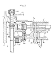
- Figure 2 is a sectional view taken along line II-II of Figure 1;
- Figure 3 is a perspective view of an essential part of Figure 1; and
- Figure 4 is an enlarged sectional view of the detent arm.
- Referring to Figures 1 and 2, in the illustrated automatic transmission system, a part of a
torque converter case 1 accommodating a torque converter not shown in the drawings is formed as anoil path body 1 a having various oil passages defined on its outer surface. Amain valve body 2 is attached to thisoil path body 1 a in such a manner that various oil passages may be defined and communicated as required between theoil path body 1 a and themain valve body 2. On the outer surface of themain valve body 2 are attached asecondary valve body 3a, and aservo valve body 3b one over the other in that order. Themain valve body 2, thesecondary valve body 3a and theservo valve body 3b are covered by atransmission case 6. - The
main valve body 2 accommodates therein a manual valve element 4 forming a manual valve in cooperation with themain valve body 2 for selecting a shift position by acting upon a hydraulic circuit not shown in the drawings. Thesecondary valve body 3a likewise defines various valves therein, and thevalve element 9 of only one of such valves is shown in Figure 2. The bore slidably receiving thisvalve element 9 is closed by acylindrical plug 9a which is in turn prevented from coming off by apin 9b passed through thesecondary valve body 3a. - One end of the manual valve element 4 projects from the
main valve body 2, and its hookedend portion 4a is engaged with a free end of atransmission arm 5 via a pin 7 (Figure 3). The base end of thetransmission arm 5 is fitted onto acontrol shaft 8 rotatably passed through thetorque converter case 1, and is secured against both axial and radial movements relative to the control shaft by apin 10. The end of thecontrol shaft 8 on the other side of the wall of theconverter case 1 integrally carries alever 11 via a threadedbolt 12, and the free end of thislever 11 is functionally connected to a shift lever provided in the passenger compartment but not shown in the drawings. - The base end of the
transmission arm 5 is formed with acylindrical extension 5a extending away from the wall of thetorque converter case 1, and a base end of a sector-shapeddetent cam plate 14 is integrally attached to thecylindrical extension 5a by welding. Therefore, thecontrol shaft 8, thetransmission arm 5 and thedetent cam plate 14 rotate integrally with each other. The free end of thedetent cam plate 14 is provided with awavy cam surface 14a to which aroller 17 of adetent arm 15 abuts as described hereinafter. A middle part of thedetent cam plate 14 is provided with a through hole 14b so as to facilitate the positioning of thedetent cam plate 14 when mounting it on thecylindrical extension 5a of thetransmission arm 5. - The base end of the
detent arm 15 is rotatably supported between themain valve body 2 and the servo valve body 3 via apin 16 which is fitted into themain valve body 2 at its one end and into the servevalve body 3a at its other end in such a manner that the swing shaft of thedetent arm 15 extends in parallel with thecontrol shaft 8. As shown in Figure 3, thispin 16 also engages with a planar portion 4b of the manual valve element 4 so that the rotation of the manual valve element 4 may be restricted, and the proper communication between the ports and oil passages of themain valve body 2 may be ensured. Optionally, as shown by the imaginary line 16' in Figure 3, thepin 16 may also be passed into a registration hole provided in theoil path body 1 a so that themain valve body 2 may be accurately positioned relative to theoil path body 1 a. - As illustrated in Figure 4 in enlarged scale, the free end of the
detent arm 15 is bifurcated, and throughholes 15a are passed through the bifurcated ends. Aroller 17 for engaging with thecam surface 14a of thedetent cam plate 14 is rotatably supported in the throughholes 15a viabearings 18 so that the force required to rotate thedetent cam plate 14 with the shift lever may be reduced. Theroller 17 and thebearings 18 are prevented from coming off by crimping each end of the throughholes 15a. Ahook portion 15b is integrally provided in a suitable location on the free end of thedetent arm 15, and an end of atension coil spring 20 is engaged with thishook portion 15b. The other end of thetension coil spring 20 is engaged with thecontrol shaft 8 itself. Therefore, thedetent arm 15 is always urged toward thedetent cam plate 14, and theroller 17 is always engaged with thecam surface 14a. Thehook portion 15b has its edges rounded so that the associated end portion of thetension coil spring 20 may not be damaged by scraping. Thetension coil spring 20 is surrounded by arubber cover 21 so as to prevent undesirable vibration of thetension coil spring 20. - Now the operation of this embodiment is described in the following.
- When the operator of the motor vehicle operates the shift lever, the manual valve element 4 is actuated by way of the
lever 11, thecontrol shaft 8 and thetransmission arm 5, and the shifting of the gears takes place. Thecam surface 14a of thedetent cam plate 14 is provided with depressions according to different shift positions such as P (parking), R (reverse), N (neutral) and D (forward drive), and the manual valve element 4 can be held in each of the shift positions with a suitable retaining force which is produced by theroller 17 being urged into each of the depressions provided in thecam surface 14a of thedetent cam plate 14 and transmitted thereto via thedetent cam plate 14, thecontrol shaft 8 and thetransmission arm 5. This retaining force is also transmitted to the shift lever which is operated by the operator of the vehicle. - Thus, according to the present invention, since no extra radial force is applied to the opening provided on the casing of the transmission system for rotatably supporting the control shaft, the force required to operate the shift lever would not be increased from the initially designed level. Further, by using a tension coil spring as the spring means, the freedom of design such as spatial layout is improved. In short, the present invention offers a significant advantage in this technical field.
- Although the present invention has been described in terms of a preferred embodiment thereof, it is obvious to a person skilled in the art that various alterations and modifications are possible without departing from the scope of the present invention which is set forth in the appended claims.
Claims (5)
Applications Claiming Priority (2)
| Application Number | Priority Date | Filing Date | Title |
|---|---|---|---|
| JP1990100482U JP2569260Y2 (en) | 1990-09-26 | 1990-09-26 | Automatic transmission detent structure |
| JP100482/90 | 1990-09-26 |
Publications (2)
| Publication Number | Publication Date |
|---|---|
| EP0477603A1 true EP0477603A1 (en) | 1992-04-01 |
| EP0477603B1 EP0477603B1 (en) | 1994-11-17 |
Family
ID=14275146
Family Applications (1)
| Application Number | Title | Priority Date | Filing Date |
|---|---|---|---|
| EP91114858A Expired - Lifetime EP0477603B1 (en) | 1990-09-26 | 1991-09-03 | Detent structure for an automatic transmission system |
Country Status (4)
| Country | Link |
|---|---|
| US (1) | US5123294A (en) |
| EP (1) | EP0477603B1 (en) |
| JP (1) | JP2569260Y2 (en) |
| DE (1) | DE69105180T2 (en) |
Cited By (1)
| Publication number | Priority date | Publication date | Assignee | Title |
|---|---|---|---|---|
| DE19628099A1 (en) * | 1996-07-12 | 1998-01-15 | Bayerische Motoren Werke Ag | Automatic transmission for motor vehicle |
Families Citing this family (4)
| Publication number | Priority date | Publication date | Assignee | Title |
|---|---|---|---|---|
| KR20020031644A (en) * | 2000-10-20 | 2002-05-03 | 이계안 | Manual valve of hydraulic control system for automatic transmission |
| JP5297923B2 (en) * | 2009-07-14 | 2013-09-25 | 本田技研工業株式会社 | Detent structure of automatic transmission |
| ITMO20100303A1 (en) * | 2010-10-29 | 2012-04-30 | Cnh Italia Spa | CONTROL DEVICE FOR A TRACKED VEHICLE. |
| JP6390830B2 (en) * | 2014-04-24 | 2018-09-19 | 三菱自動車工業株式会社 | Detent spring |
Citations (3)
| Publication number | Priority date | Publication date | Assignee | Title |
|---|---|---|---|---|
| DE874992C (en) * | 1943-06-27 | 1953-04-30 | Daimler Benz Ag | Switching device for change gears, especially in motor vehicles |
| DE1854995U (en) * | 1962-02-22 | 1962-07-12 | Willi Seehafer | DEVICE FOR FIXING SWIVELING MACHINE PARTS, IN PARTICULAR SWIVELING WHEEL SUPPORT FORKS ON VEHICLE TRAILERS. |
| US4485689A (en) * | 1983-01-10 | 1984-12-04 | Hurst Performance, Inc. | Shift control assembly |
Family Cites Families (4)
| Publication number | Priority date | Publication date | Assignee | Title |
|---|---|---|---|---|
| JPS6094858A (en) * | 1984-09-18 | 1985-05-28 | Nissan Motor Co Ltd | Park lock device for automatic transmission |
| US4704917A (en) * | 1984-12-28 | 1987-11-10 | Kanda Tekko Kabushiki Kaisha | Transfer system for vehicles |
| JPS6487417A (en) * | 1987-09-25 | 1989-03-31 | Nippon Denso Co | Method and device for transferring pallet |
| JPH02138568A (en) * | 1988-11-18 | 1990-05-28 | Komatsu Ltd | Electric transmission change-over lever |
-
1990
- 1990-09-26 JP JP1990100482U patent/JP2569260Y2/en not_active Expired - Lifetime
-
1991
- 1991-08-19 US US07/746,531 patent/US5123294A/en not_active Expired - Lifetime
- 1991-09-03 DE DE69105180T patent/DE69105180T2/en not_active Expired - Lifetime
- 1991-09-03 EP EP91114858A patent/EP0477603B1/en not_active Expired - Lifetime
Patent Citations (3)
| Publication number | Priority date | Publication date | Assignee | Title |
|---|---|---|---|---|
| DE874992C (en) * | 1943-06-27 | 1953-04-30 | Daimler Benz Ag | Switching device for change gears, especially in motor vehicles |
| DE1854995U (en) * | 1962-02-22 | 1962-07-12 | Willi Seehafer | DEVICE FOR FIXING SWIVELING MACHINE PARTS, IN PARTICULAR SWIVELING WHEEL SUPPORT FORKS ON VEHICLE TRAILERS. |
| US4485689A (en) * | 1983-01-10 | 1984-12-04 | Hurst Performance, Inc. | Shift control assembly |
Cited By (1)
| Publication number | Priority date | Publication date | Assignee | Title |
|---|---|---|---|---|
| DE19628099A1 (en) * | 1996-07-12 | 1998-01-15 | Bayerische Motoren Werke Ag | Automatic transmission for motor vehicle |
Also Published As
| Publication number | Publication date |
|---|---|
| EP0477603B1 (en) | 1994-11-17 |
| US5123294A (en) | 1992-06-23 |
| DE69105180D1 (en) | 1994-12-22 |
| DE69105180T2 (en) | 1995-03-23 |
| JPH0456969U (en) | 1992-05-15 |
| JP2569260Y2 (en) | 1998-04-22 |
Similar Documents
| Publication | Publication Date | Title |
|---|---|---|
| US6658960B2 (en) | Transmission shift position sensor | |
| US8464601B2 (en) | Actuating device comprising a locking mechanism | |
| CN100417843C (en) | Gearing controller of automatic gear | |
| CA2038464A1 (en) | Vehicle transmission with manually shifted lower gears and automatically shifted upper gears | |
| US5195387A (en) | Gear selector device for a vehicle gearbox | |
| US6877390B2 (en) | Shift range changeover mechanism | |
| US4476740A (en) | Shift mechanism for change-speed gear transmission | |
| JP2003531773A (en) | Shifting device for automobile transmission | |
| US5123294A (en) | Detent structure for an automatic transmission system | |
| US3646828A (en) | Transmission controls | |
| US20180266451A1 (en) | Actuator and fluid pressure control circuit having the same | |
| US4275618A (en) | Control device for motor road vehicle automatic change-speed transmission mechanism | |
| KR100736954B1 (en) | Automatic-transmission | |
| WO2006083221A1 (en) | A control device for a semi-automatic gearbox to be used in a vehicle and an arrangement in a vehicle comprising such a control device | |
| US6070485A (en) | Pushbutton solenoid shifter | |
| US20150114792A1 (en) | Hinge pillar assembly | |
| GB2357323A (en) | A gear-shift mechanism which shifts to a low gear when a sensor fails | |
| US3748929A (en) | Variable power train and control | |
| EP3914839A2 (en) | Rotary shifter assembly | |
| US20030159534A1 (en) | Transmission shift position sensor | |
| US11971073B2 (en) | Rotary shifter assembly | |
| KR100188862B1 (en) | Restriction device of neutral position in manual transmission | |
| JP3083743B2 (en) | Operation lever mechanism for transmission | |
| US4891999A (en) | Shift control system for a hydromechanical tractor transmission | |
| JPS61119854A (en) | Shift control device for automatic transmission gear for vehicle |
Legal Events
| Date | Code | Title | Description |
|---|---|---|---|
| PUAI | Public reference made under article 153(3) epc to a published international application that has entered the european phase |
Free format text: ORIGINAL CODE: 0009012 |
|
| AK | Designated contracting states |
Kind code of ref document: A1 Designated state(s): DE GB |
|
| 17P | Request for examination filed |
Effective date: 19920918 |
|
| 17Q | First examination report despatched |
Effective date: 19930930 |
|
| GRAA | (expected) grant |
Free format text: ORIGINAL CODE: 0009210 |
|
| AK | Designated contracting states |
Kind code of ref document: B1 Designated state(s): DE GB |
|
| REF | Corresponds to: |
Ref document number: 69105180 Country of ref document: DE Date of ref document: 19941222 |
|
| PLBE | No opposition filed within time limit |
Free format text: ORIGINAL CODE: 0009261 |
|
| STAA | Information on the status of an ep patent application or granted ep patent |
Free format text: STATUS: NO OPPOSITION FILED WITHIN TIME LIMIT |
|
| 26N | No opposition filed | ||
| REG | Reference to a national code |
Ref country code: GB Ref legal event code: IF02 |
|
| PGFP | Annual fee paid to national office [announced via postgrant information from national office to epo] |
Ref country code: GB Payment date: 20100901 Year of fee payment: 20 |
|
| PGFP | Annual fee paid to national office [announced via postgrant information from national office to epo] |
Ref country code: DE Payment date: 20100901 Year of fee payment: 20 |
|
| REG | Reference to a national code |
Ref country code: DE Ref legal event code: R071 Ref document number: 69105180 Country of ref document: DE |
|
| REG | Reference to a national code |
Ref country code: DE Ref legal event code: R071 Ref document number: 69105180 Country of ref document: DE |
|
| REG | Reference to a national code |
Ref country code: GB Ref legal event code: PE20 Expiry date: 20110902 |
|
| PG25 | Lapsed in a contracting state [announced via postgrant information from national office to epo] |
Ref country code: GB Free format text: LAPSE BECAUSE OF EXPIRATION OF PROTECTION Effective date: 20110902 |
|
| PG25 | Lapsed in a contracting state [announced via postgrant information from national office to epo] |
Ref country code: DE Free format text: LAPSE BECAUSE OF EXPIRATION OF PROTECTION Effective date: 20110904 |