EP0477475A2 - An improved refrigeration circuit and method of de-frosting it - Google Patents
An improved refrigeration circuit and method of de-frosting it Download PDFInfo
- Publication number
- EP0477475A2 EP0477475A2 EP91110116A EP91110116A EP0477475A2 EP 0477475 A2 EP0477475 A2 EP 0477475A2 EP 91110116 A EP91110116 A EP 91110116A EP 91110116 A EP91110116 A EP 91110116A EP 0477475 A2 EP0477475 A2 EP 0477475A2
- Authority
- EP
- European Patent Office
- Prior art keywords
- evaporator
- compressor
- frosting
- refrigeration circuit
- counter
- Prior art date
- Legal status (The legal status is an assumption and is not a legal conclusion. Google has not performed a legal analysis and makes no representation as to the accuracy of the status listed.)
- Granted
Links
Images
Classifications
-
- F—MECHANICAL ENGINEERING; LIGHTING; HEATING; WEAPONS; BLASTING
- F25—REFRIGERATION OR COOLING; COMBINED HEATING AND REFRIGERATION SYSTEMS; HEAT PUMP SYSTEMS; MANUFACTURE OR STORAGE OF ICE; LIQUEFACTION SOLIDIFICATION OF GASES
- F25B—REFRIGERATION MACHINES, PLANTS OR SYSTEMS; COMBINED HEATING AND REFRIGERATION SYSTEMS; HEAT PUMP SYSTEMS
- F25B5/00—Compression machines, plants or systems, with several evaporator circuits, e.g. for varying refrigerating capacity
- F25B5/04—Compression machines, plants or systems, with several evaporator circuits, e.g. for varying refrigerating capacity arranged in series
-
- F—MECHANICAL ENGINEERING; LIGHTING; HEATING; WEAPONS; BLASTING
- F25—REFRIGERATION OR COOLING; COMBINED HEATING AND REFRIGERATION SYSTEMS; HEAT PUMP SYSTEMS; MANUFACTURE OR STORAGE OF ICE; LIQUEFACTION SOLIDIFICATION OF GASES
- F25B—REFRIGERATION MACHINES, PLANTS OR SYSTEMS; COMBINED HEATING AND REFRIGERATION SYSTEMS; HEAT PUMP SYSTEMS
- F25B47/00—Arrangements for preventing or removing deposits or corrosion, not provided for in another subclass
- F25B47/02—Defrosting cycles
- F25B47/022—Defrosting cycles hot gas defrosting
Definitions
- This invention relates to an improved refrigeration circuit, particularly of the type which is incorporated to refrigerated display counters and comprises a refrigerating gas compressor, a condenser, a first evaporator and at least one second evaporator connected in series to each other, and evaporator de-frosting means.
- the invention also relates to a refrigerated counter having a refrigeration circuit which comprises a series of a first evaporator operating in conductive heat transfer with one or more walls of the counter and with a second finned or convective transfer evaporator which, in operation of the refrigerated counter, is swept by a forced air flow to enhance the convective heat transfer.
- the invention further relates to a method of de-frosting such circuit and counter.
- This operation is usually performed through heater means incorporated to the counter itself.
- a known technical solution for meeting this demand provides for the conveying of all the "hot" refrigerating gas available at the compressor outlet through both evaporators, bypassing the condenser.
- the circuit ceases to operate in accord with a refrigeration cycle throughout the duration of the de-frosting step. It follows that the heat available to de-frost is that deriving from the energy dissipated by the compressor. In addition, both evaporators are de-frosted, and this unavoidably involves a longer de-frosting time and longer pickup time for the refrigeration cycle to recover its running temperature.
- the technical problem addressed by this invention is to provide a refrigeration circuit having such structural and functional characteristics as to overcome the above-mentioned drawbacks with which the prior art is beset.
- the solutive idea on which the invention stands consists of tapping off a fraction of the "hot” refrigerating gas downstream from the compressor, while the remainder is allowed to carry on the refrigeration cycle, and admixing it, upstream of the second evaporator, to the "cool" refrigerating gas from the first evaporator.
- a circuit as indicated being characterized in that said means comprise a bypass connection between the compressor outlet and the inlet to the second evaporator.
- a pre-set solenoid valve is provided in the said bypass connection.
- a method of de-frosting a refrigeration circuit comprising a refrigerating gas compressor, a condenser, and a first evaporator and at least one second evaporator connected serially to each other, characterized by tapping off some of the refrigerating gas downstream from the compressor and supplying the second evaporator with a mixture of said gas and gas exiting the first evaporator.
- a refrigeration circuit embodying this invention is intended for installation in a refrigerated display counter 2 of which the remaining structural elements are conventional.
- the circuit 1 utilizes the properties of a suitable conventional refrigerating fluid, such as freon, which forms the working fluid through the operation cycles to be described.
- a suitable conventional refrigerating fluid such as freon
- the circuit 1 comprises a compressor 3 having an outlet 4 in fluid communication with the inlet 9 of a condenser 5. Said condenser is cooled by a fan 6 driven by a motor 7.
- the condenser has an outlet 8 connected to the inlet 19 of a first evaporator 10 through a series of a de-watering filter 11 and a capillary 12.
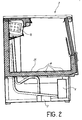
- the evaporator 10 is placed in substantial contact with a vat-like wall 25 of the counter 2 intended to contain the products to be preserved, in an essentially conductive heat transfer relationship with that wall 25.
- This first evaporator 10 is connected serially to a second, finned evaporator 13 which is in a substantially convective heat transfer relationship with its environment.
- This second evaporator has an outlet 14 connected to the inlet of the compressor 3.
- the circuit 1 comprises de-frosting means 15 for the evaporator 13.
- Such means 15 comprise a one-way bypass connection 17 between the outlet 4 of the compressor 3 and the inlet of the second evaporator 13.
- a solenoid valve 16 which is pre-set at a selected flow rate of the refrigerating fluid below the overall flow rate at the delivery outlet of the compressor 3, is provided in the connection 17.
- the circuit 1 is essentially composed of a pair of circuit links 18, 20.
- the first link 18 comprises the compressor 3, valve 16, and second evaporator 13; and the second link 20 includes, in turn, the compressor 3, condenser 5, and series of the evaporators 10, 13.
- valve 16 When it is desired to start de-frosting the counter 2, the valve 16 is operated to an open position, and some of the fluid exiting the compressor 3 is tapped off the second circuit link 20 and directed into the second evaporator 13, over the connection 17.
- the second evaporator 13 is supplied with a comparatively warm fluid consisting of the fluid exiting the first evaporator 10 and the fluid delivered from the compressor 3, mixed together.
- the invention solves the aforementioned technical problem in a cost-efficient and effective manner.
- a major advantage of the refrigeration circuit of this invention is that during the step of de-frosting the second evaporator, at least some of the refrigerating fluid is caused to undergo a normal refrigeration cycle, thereby enhancing the overall efficiency of the circuit.
- the first evaporator that is the one directly contacting the products preserved in the refrigerated counter, will undergo no heating. This fact, besides affording quicker restoration of the cooling cycle, also prevents the products preserved under the counter from becoming heated and possibly damaged while de-frosting.
Landscapes
- Engineering & Computer Science (AREA)
- Physics & Mathematics (AREA)
- Mechanical Engineering (AREA)
- Thermal Sciences (AREA)
- General Engineering & Computer Science (AREA)
- Defrosting Systems (AREA)
- Interface Circuits In Exchanges (AREA)
- Devices That Are Associated With Refrigeration Equipment (AREA)
Abstract
Description
- This invention relates to an improved refrigeration circuit, particularly of the type which is incorporated to refrigerated display counters and comprises a refrigerating gas compressor, a condenser, a first evaporator and at least one second evaporator connected in series to each other, and evaporator de-frosting means.
- The invention also relates to a refrigerated counter having a refrigeration circuit which comprises a series of a first evaporator operating in conductive heat transfer with one or more walls of the counter and with a second finned or convective transfer evaporator which, in operation of the refrigerated counter, is swept by a forced air flow to enhance the convective heat transfer.
- The invention further relates to a method of de-frosting such circuit and counter.
- It is well known that in the specific technical field of this invention it becomes necessary to periodically de-frost the refrigerated counter.
- This operation is usually performed through heater means incorporated to the counter itself.
- For instance, a known technical solution for meeting this demand provides for the conveying of all the "hot" refrigerating gas available at the compressor outlet through both evaporators, bypassing the condenser.
- Owing to this technique temporarily eliminating the condensation and evaporation steps, the circuit ceases to operate in accord with a refrigeration cycle throughout the duration of the de-frosting step. It follows that the heat available to de-frost is that deriving from the energy dissipated by the compressor. In addition, both evaporators are de-frosted, and this unavoidably involves a longer de-frosting time and longer pickup time for the refrigeration cycle to recover its running temperature.
- Another drawback of this de-frosting technique comes from that the first evaporator is usually installed on the bottom of the refrigerated counter, in direct contact with the products to be preserved, which accordingly undergo undesired heating while de-frosting.
- Further, it has been observed that the compressor operates, during the de-frosting step, outside its design thermal range, resulting in overheating and shortened life of the same.
- The technical problem addressed by this invention is to provide a refrigeration circuit having such structural and functional characteristics as to overcome the above-mentioned drawbacks with which the prior art is beset.
- The solutive idea on which the invention stands consists of tapping off a fraction of the "hot" refrigerating gas downstream from the compressor, while the remainder is allowed to carry on the refrigeration cycle, and admixing it, upstream of the second evaporator, to the "cool" refrigerating gas from the first evaporator.
- In this way, at least some of the refrigerating gas is subjected to a normal refrigeration cycle even during the de-frosting step, which results in improved overall efficiency of the circuit.
- Based on this idea, the aforementioned technical problem is solved by a circuit as indicated being characterized in that said means comprise a bypass connection between the compressor outlet and the inlet to the second evaporator.
- In a preferred embodiment, a pre-set solenoid valve is provided in the said bypass connection.
- This technical problem is also solved by a method of de-frosting a refrigeration circuit comprising a refrigerating gas compressor, a condenser, and a first evaporator and at least one second evaporator connected serially to each other, characterized by tapping off some of the refrigerating gas downstream from the compressor and supplying the second evaporator with a mixture of said gas and gas exiting the first evaporator.
- The features and advantages of the refrigeration circuit according to the invention will be apparent from the following detailed description of an embodiment thereof, shown by way of illustration and not of limitation in the accompanying drawings.
- In the drawings:
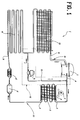
- Figure 1 is a schematic view of the refrigeration circuit according to the invention;
- Figure 2 is a cross-sectional view of a refrigerated display counter incorporating the refrigeration circuit of this invention.
- With reference to these drawing figures, generally and schematically shown at 1 is a refrigeration circuit embodying this invention and being intended for installation in a refrigerated
display counter 2 of which the remaining structural elements are conventional. - The circuit 1 utilizes the properties of a suitable conventional refrigerating fluid, such as freon, which forms the working fluid through the operation cycles to be described.
- The circuit 1 comprises a
compressor 3 having anoutlet 4 in fluid communication with the inlet 9 of acondenser 5. Said condenser is cooled by a fan 6 driven by amotor 7. - The condenser has an outlet 8 connected to the
inlet 19 of afirst evaporator 10 through a series of ade-watering filter 11 and a capillary 12. - The
evaporator 10 is placed in substantial contact with a vat-like wall 25 of thecounter 2 intended to contain the products to be preserved, in an essentially conductive heat transfer relationship with thatwall 25. Thisfirst evaporator 10 is connected serially to a second,finned evaporator 13 which is in a substantially convective heat transfer relationship with its environment. - This second evaporator has an
outlet 14 connected to the inlet of thecompressor 3. - The circuit 1 comprises de-frosting means 15 for the
evaporator 13. - Such means 15 comprise a one-
way bypass connection 17 between theoutlet 4 of thecompressor 3 and the inlet of thesecond evaporator 13. - A
solenoid valve 16, which is pre-set at a selected flow rate of the refrigerating fluid below the overall flow rate at the delivery outlet of thecompressor 3, is provided in theconnection 17. - By the provision of the
connection 17, the circuit 1 is essentially composed of a pair ofcircuit links first link 18 comprises thecompressor 3,valve 16, andsecond evaporator 13; and thesecond link 20 includes, in turn, thecompressor 3,condenser 5, and series of theevaporators - When it is desired to start de-frosting the
counter 2, thevalve 16 is operated to an open position, and some of the fluid exiting thecompressor 3 is tapped off thesecond circuit link 20 and directed into thesecond evaporator 13, over theconnection 17. - Thus, the
second evaporator 13 is supplied with a comparatively warm fluid consisting of the fluid exiting thefirst evaporator 10 and the fluid delivered from thecompressor 3, mixed together. - Nonetheless, the refrigeration cycle through the
link 20 is completed, albeit at a reduced rate, by the remainder of the refrigerating fluid which still flows through thecondenser 5. - Thus, the invention solves the aforementioned technical problem in a cost-efficient and effective manner.
- A major advantage of the refrigeration circuit of this invention is that during the step of de-frosting the second evaporator, at least some of the refrigerating fluid is caused to undergo a normal refrigeration cycle, thereby enhancing the overall efficiency of the circuit.
- In this way, the first evaporator, that is the one directly contacting the products preserved in the refrigerated counter, will undergo no heating. This fact, besides affording quicker restoration of the cooling cycle, also prevents the products preserved under the counter from becoming heated and possibly damaged while de-frosting.
Claims (5)
- An improved refrigeration circuit,
particularly of the type which is incorporated to refrigerated display counters and comprising a refrigerating gas compressor (3), a condenser (5), a first evaporator and at least one second evaporator (10,13) connected in series to each other, and evaporator de-frosting means, characterized in that said means comprise a bypass connection (17) between the compressor (3) outlet and the inlet to the second evaporator (13). - A refrigeration circuit according to Claim 1, characterized in that provided in said bypass connection (17) is a valve (16) pre-set to a selected gas flow rate below the overall flow rate of said compressor (3).
- A refrigerated counter, characterized in that it incorporates a refrigeration circuit (1) according to either claim 1 or 2.
- A refrigerated counter according to Claim 3, wherein the first evaporator (10) is in conductive heat transfer communication with one or more walls (25) of the counter, and the second evaporator (13) is a finned or convective heat transfer one.
- A method of de-frosting a refrigeration circuit comprising a refrigerating gas compressor, a condenser, and a first evaporator and at least one second evaporator connected serially to each other, characterized by tapping off some of the refrigerating gas downstream from the compressor and supplying the second evaporator with a mixture of said gas and gas exiting the first evaporator.
Applications Claiming Priority (2)
| Application Number | Priority Date | Filing Date | Title |
|---|---|---|---|
| IT04169990A IT1244107B (en) | 1990-09-28 | 1990-09-28 | REFRIGERATED REFRIGERANT CIRCUIT AND RELATED DEFROSTING METHOD |
| IT4169990 | 1990-09-28 |
Publications (3)
| Publication Number | Publication Date |
|---|---|
| EP0477475A2 true EP0477475A2 (en) | 1992-04-01 |
| EP0477475A3 EP0477475A3 (en) | 1992-09-02 |
| EP0477475B1 EP0477475B1 (en) | 1994-12-21 |
Family
ID=11253142
Family Applications (1)
| Application Number | Title | Priority Date | Filing Date |
|---|---|---|---|
| EP91110116A Expired - Lifetime EP0477475B1 (en) | 1990-09-28 | 1991-06-20 | An improved refrigeration circuit and method of de-frosting it |
Country Status (6)
| Country | Link |
|---|---|
| EP (1) | EP0477475B1 (en) |
| AT (1) | ATE116054T1 (en) |
| DE (1) | DE69106096T2 (en) |
| DK (1) | DK0477475T3 (en) |
| ES (1) | ES2066276T3 (en) |
| IT (1) | IT1244107B (en) |
Cited By (9)
| Publication number | Priority date | Publication date | Assignee | Title |
|---|---|---|---|---|
| WO1994020803A1 (en) * | 1993-03-08 | 1994-09-15 | Greenhalgh Refrigeration Pty Ltd | Refrigeration process and apparatus |
| EP0699883A3 (en) * | 1994-08-31 | 1996-07-24 | Nippon Denso Co | Refrigerating system |
| US6935127B2 (en) * | 2002-08-31 | 2005-08-30 | Samsung Electronics Co., Ltd. | Refrigerator |
| EP1825839A1 (en) | 2006-02-28 | 2007-08-29 | Ostomycure AS | Implant |
| US7370490B2 (en) * | 2005-06-30 | 2008-05-13 | Zhiming Li | Air-conditioning system with full heat recovery |
| CN102003842A (en) * | 2010-11-04 | 2011-04-06 | 三花丹佛斯(杭州)微通道换热器有限公司 | Evaporator and refrigeration system with same |
| EP2364678A1 (en) | 2007-08-21 | 2011-09-14 | Ostomycure AS | Implant |
| CN104848497A (en) * | 2015-06-10 | 2015-08-19 | 广东志高暖通设备股份有限公司 | Air conditioner |
| CN105402937A (en) * | 2015-12-22 | 2016-03-16 | 广东志高暖通设备股份有限公司 | Air-conditioning system |
Families Citing this family (6)
| Publication number | Priority date | Publication date | Assignee | Title |
|---|---|---|---|---|
| JP2007040658A (en) * | 2005-08-05 | 2007-02-15 | Matsushita Electric Ind Co Ltd | Air conditioner |
| GB201105126D0 (en) | 2011-03-25 | 2011-05-11 | Ostomycure As | Percutaneous implant and ostomy method |
| USD827824S1 (en) | 2013-04-30 | 2018-09-04 | Ostomycure As | Implant with internal porous surface structure |
| USD752750S1 (en) | 2013-04-30 | 2016-03-29 | Ostomycure As | Implants |
| BR302013005473S1 (en) | 2013-04-30 | 2014-12-23 | Ostomycure As | CONFIGURATION APPLIED TO A MEDICAL DEVICE |
| US11371760B2 (en) * | 2018-07-27 | 2022-06-28 | Mitsubishi Electric Corporation | Refrigeration cycle apparatus |
Citations (3)
| Publication number | Priority date | Publication date | Assignee | Title |
|---|---|---|---|---|
| US2801523A (en) * | 1952-05-15 | 1957-08-06 | Charles C Hansen | Defrosting apparatus for refrigeration systems |
| US2909907A (en) * | 1958-11-25 | 1959-10-27 | Whirlpool Co | Refrigerating apparatus with hot gas defrost means |
| US4949554A (en) * | 1989-09-08 | 1990-08-21 | Specialty Equipment Companies, Inc. | Single pane, curved glass lid, frozen food merchandiser |
-
1990
- 1990-09-28 IT IT04169990A patent/IT1244107B/en active IP Right Grant
-
1991
- 1991-06-20 EP EP91110116A patent/EP0477475B1/en not_active Expired - Lifetime
- 1991-06-20 DE DE69106096T patent/DE69106096T2/en not_active Expired - Fee Related
- 1991-06-20 ES ES91110116T patent/ES2066276T3/en not_active Expired - Lifetime
- 1991-06-20 DK DK91110116.0T patent/DK0477475T3/en active
- 1991-06-20 AT AT91110116T patent/ATE116054T1/en not_active IP Right Cessation
Patent Citations (3)
| Publication number | Priority date | Publication date | Assignee | Title |
|---|---|---|---|---|
| US2801523A (en) * | 1952-05-15 | 1957-08-06 | Charles C Hansen | Defrosting apparatus for refrigeration systems |
| US2909907A (en) * | 1958-11-25 | 1959-10-27 | Whirlpool Co | Refrigerating apparatus with hot gas defrost means |
| US4949554A (en) * | 1989-09-08 | 1990-08-21 | Specialty Equipment Companies, Inc. | Single pane, curved glass lid, frozen food merchandiser |
Non-Patent Citations (1)
| Title |
|---|
| AIR CONDITIONING HEATING AND VENTILATING. vol. 65, no. 1, January 1968, CALDWELL US pages 64 - 68; C.G. KIRKMAN: 'Automatic Hot Gas Bypass' * |
Cited By (11)
| Publication number | Priority date | Publication date | Assignee | Title |
|---|---|---|---|---|
| WO1994020803A1 (en) * | 1993-03-08 | 1994-09-15 | Greenhalgh Refrigeration Pty Ltd | Refrigeration process and apparatus |
| EP0699883A3 (en) * | 1994-08-31 | 1996-07-24 | Nippon Denso Co | Refrigerating system |
| US6935127B2 (en) * | 2002-08-31 | 2005-08-30 | Samsung Electronics Co., Ltd. | Refrigerator |
| US7370490B2 (en) * | 2005-06-30 | 2008-05-13 | Zhiming Li | Air-conditioning system with full heat recovery |
| EP1825839A1 (en) | 2006-02-28 | 2007-08-29 | Ostomycure AS | Implant |
| US8647304B2 (en) | 2006-02-28 | 2014-02-11 | Ostomycure As | Implant and method for its manufacture |
| EP2364678A1 (en) | 2007-08-21 | 2011-09-14 | Ostomycure AS | Implant |
| CN102003842A (en) * | 2010-11-04 | 2011-04-06 | 三花丹佛斯(杭州)微通道换热器有限公司 | Evaporator and refrigeration system with same |
| CN102003842B (en) * | 2010-11-04 | 2013-04-10 | 三花控股集团有限公司 | Evaporator and refrigeration system with same |
| CN104848497A (en) * | 2015-06-10 | 2015-08-19 | 广东志高暖通设备股份有限公司 | Air conditioner |
| CN105402937A (en) * | 2015-12-22 | 2016-03-16 | 广东志高暖通设备股份有限公司 | Air-conditioning system |
Also Published As
| Publication number | Publication date |
|---|---|
| DK0477475T3 (en) | 1995-05-15 |
| DE69106096D1 (en) | 1995-02-02 |
| ES2066276T3 (en) | 1995-03-01 |
| EP0477475A3 (en) | 1992-09-02 |
| EP0477475B1 (en) | 1994-12-21 |
| IT9041699A1 (en) | 1992-03-28 |
| ATE116054T1 (en) | 1995-01-15 |
| IT9041699A0 (en) | 1990-09-28 |
| DE69106096T2 (en) | 1995-05-04 |
| IT1244107B (en) | 1994-07-05 |
Similar Documents
| Publication | Publication Date | Title |
|---|---|---|
| EP0477475B1 (en) | An improved refrigeration circuit and method of de-frosting it | |
| US6170270B1 (en) | Refrigeration system using liquid-to-liquid heat transfer for warm liquid defrost | |
| US5921092A (en) | Fluid defrost system and method for secondary refrigeration systems | |
| US6094925A (en) | Crossover warm liquid defrost refrigeration system | |
| US4565070A (en) | Apparatus and method for defrosting a heat exchanger in a refrigeration circuit | |
| CA1090307A (en) | Control for a combination furnace and heat pump system | |
| US4474026A (en) | Refrigerating apparatus | |
| JPS645717Y2 (en) | ||
| CA1177268A (en) | Airconditioner with refrigerant temperature responsive controller for compressor bypass valve | |
| US4646539A (en) | Transport refrigeration system with thermal storage sink | |
| US5669222A (en) | Refrigeration passive defrost system | |
| US4798058A (en) | Hot gas defrost system for refrigeration systems and apparatus therefor | |
| US5771699A (en) | Three coil electric heat pump | |
| WO1990008931A1 (en) | Hot gas defrost system for refrigeration systems | |
| US3365902A (en) | Reverse cycle refrigeration system | |
| US6263686B1 (en) | Defrost control method and apparatus | |
| EP0301728B1 (en) | Hot gas defrost system for refrigeration systems and apparatus therefor | |
| GB2200444A (en) | Air conditioner system with heating operation assist function | |
| CA2415993A1 (en) | Air conditioning system, interior heat exchanger coil unit and method for conditioning ambient air | |
| US4095438A (en) | Refrigeration system with hot gas defrost | |
| GB2062829A (en) | Heat pump or refrigeration circuits | |
| US5715690A (en) | Microwave thermal heat pump defroster | |
| CN111947377A (en) | Diversified refrigeration equipment and control method and device thereof | |
| JPH05126440A (en) | Freezer | |
| JP2720996B2 (en) | Engine heat pump defroster |
Legal Events
| Date | Code | Title | Description |
|---|---|---|---|
| PUAI | Public reference made under article 153(3) epc to a published international application that has entered the european phase |
Free format text: ORIGINAL CODE: 0009012 |
|
| AK | Designated contracting states |
Kind code of ref document: A2 Designated state(s): AT BE CH DE DK ES FR GB GR LI LU NL SE |
|
| PUAL | Search report despatched |
Free format text: ORIGINAL CODE: 0009013 |
|
| AK | Designated contracting states |
Kind code of ref document: A3 Designated state(s): AT BE CH DE DK ES FR GB GR LI LU NL SE |
|
| 17P | Request for examination filed |
Effective date: 19921030 |
|
| 17Q | First examination report despatched |
Effective date: 19930818 |
|
| GRAA | (expected) grant |
Free format text: ORIGINAL CODE: 0009210 |
|
| AK | Designated contracting states |
Kind code of ref document: B1 Designated state(s): AT BE CH DE DK ES FR GB GR LI LU NL SE |
|
| PG25 | Lapsed in a contracting state [announced via postgrant information from national office to epo] |
Ref country code: NL Effective date: 19941221 Ref country code: LI Effective date: 19941221 Ref country code: GR Free format text: LAPSE BECAUSE OF FAILURE TO SUBMIT A TRANSLATION OF THE DESCRIPTION OR TO PAY THE FEE WITHIN THE PRESCRIBED TIME-LIMIT Effective date: 19941221 Ref country code: FR Effective date: 19941221 Ref country code: CH Effective date: 19941221 Ref country code: BE Effective date: 19941221 |
|
| REF | Corresponds to: |
Ref document number: 116054 Country of ref document: AT Date of ref document: 19950115 Kind code of ref document: T |
|
| REF | Corresponds to: |
Ref document number: 69106096 Country of ref document: DE Date of ref document: 19950202 |
|
| REG | Reference to a national code |
Ref country code: ES Ref legal event code: FG2A Ref document number: 2066276 Country of ref document: ES Kind code of ref document: T3 |
|
| REG | Reference to a national code |
Ref country code: CH Ref legal event code: PL |
|
| REG | Reference to a national code |
Ref country code: DK Ref legal event code: T3 |
|
| EN | Fr: translation not filed | ||
| NLV1 | Nl: lapsed or annulled due to failure to fulfill the requirements of art. 29p and 29m of the patents act | ||
| PG25 | Lapsed in a contracting state [announced via postgrant information from national office to epo] |
Ref country code: LU Free format text: LAPSE BECAUSE OF NON-PAYMENT OF DUE FEES Effective date: 19950630 |
|
| PLBE | No opposition filed within time limit |
Free format text: ORIGINAL CODE: 0009261 |
|
| STAA | Information on the status of an ep patent application or granted ep patent |
Free format text: STATUS: NO OPPOSITION FILED WITHIN TIME LIMIT |
|
| 26N | No opposition filed | ||
| PGFP | Annual fee paid to national office [announced via postgrant information from national office to epo] |
Ref country code: SE Payment date: 19990429 Year of fee payment: 9 |
|
| PGFP | Annual fee paid to national office [announced via postgrant information from national office to epo] |
Ref country code: DK Payment date: 19990511 Year of fee payment: 9 |
|
| PGFP | Annual fee paid to national office [announced via postgrant information from national office to epo] |
Ref country code: AT Payment date: 19990512 Year of fee payment: 9 |
|
| PGFP | Annual fee paid to national office [announced via postgrant information from national office to epo] |
Ref country code: GB Payment date: 19990517 Year of fee payment: 9 |
|
| PGFP | Annual fee paid to national office [announced via postgrant information from national office to epo] |
Ref country code: DE Payment date: 19990526 Year of fee payment: 9 |
|
| PGFP | Annual fee paid to national office [announced via postgrant information from national office to epo] |
Ref country code: ES Payment date: 19990607 Year of fee payment: 9 |
|
| PG25 | Lapsed in a contracting state [announced via postgrant information from national office to epo] |
Ref country code: GB Free format text: LAPSE BECAUSE OF NON-PAYMENT OF DUE FEES Effective date: 20000620 Ref country code: DK Free format text: LAPSE BECAUSE OF NON-PAYMENT OF DUE FEES Effective date: 20000620 Ref country code: AT Free format text: LAPSE BECAUSE OF NON-PAYMENT OF DUE FEES Effective date: 20000620 |
|
| PG25 | Lapsed in a contracting state [announced via postgrant information from national office to epo] |
Ref country code: SE Free format text: LAPSE BECAUSE OF NON-PAYMENT OF DUE FEES Effective date: 20000621 Ref country code: ES Free format text: THE PATENT HAS BEEN ANNULLED BY A DECISION OF A NATIONAL AUTHORITY Effective date: 20000621 |
|
| GBPC | Gb: european patent ceased through non-payment of renewal fee |
Effective date: 20000620 |
|
| EUG | Se: european patent has lapsed |
Ref document number: 91110116.0 |
|
| REG | Reference to a national code |
Ref country code: DK Ref legal event code: EBP |
|
| PG25 | Lapsed in a contracting state [announced via postgrant information from national office to epo] |
Ref country code: DE Free format text: LAPSE BECAUSE OF NON-PAYMENT OF DUE FEES Effective date: 20010403 |
|
| REG | Reference to a national code |
Ref country code: ES Ref legal event code: FD2A Effective date: 20020304 |