EP0477397B1 - Method to determine the contour of the machine tool path by a numerically controlled machine - Google Patents
Method to determine the contour of the machine tool path by a numerically controlled machine Download PDFInfo
- Publication number
- EP0477397B1 EP0477397B1 EP90118384A EP90118384A EP0477397B1 EP 0477397 B1 EP0477397 B1 EP 0477397B1 EP 90118384 A EP90118384 A EP 90118384A EP 90118384 A EP90118384 A EP 90118384A EP 0477397 B1 EP0477397 B1 EP 0477397B1
- Authority
- EP
- European Patent Office
- Prior art keywords
- contour
- sections
- tool path
- machine
- numerically controlled
- Prior art date
- Legal status (The legal status is an assumption and is not a legal conclusion. Google has not performed a legal analysis and makes no representation as to the accuracy of the status listed.)
- Expired - Lifetime
Links
Images

Classifications
-
- G—PHYSICS
- G05—CONTROLLING; REGULATING
- G05B—CONTROL OR REGULATING SYSTEMS IN GENERAL; FUNCTIONAL ELEMENTS OF SUCH SYSTEMS; MONITORING OR TESTING ARRANGEMENTS FOR SUCH SYSTEMS OR ELEMENTS
- G05B19/00—Program-control systems
- G05B19/02—Program-control systems electric
- G05B19/18—Numerical control [NC], i.e. automatically operating machines, in particular machine tools, e.g. in a manufacturing environment, so as to execute positioning, movement or co-ordinated operations by means of program data in numerical form
- G05B19/41—Numerical control [NC], i.e. automatically operating machines, in particular machine tools, e.g. in a manufacturing environment, so as to execute positioning, movement or co-ordinated operations by means of program data in numerical form characterised by interpolation, e.g. the computation of intermediate points between programmed end points to define the path to be followed and the rate of travel along that path
-
- G—PHYSICS
- G05—CONTROLLING; REGULATING
- G05B—CONTROL OR REGULATING SYSTEMS IN GENERAL; FUNCTIONAL ELEMENTS OF SUCH SYSTEMS; MONITORING OR TESTING ARRANGEMENTS FOR SUCH SYSTEMS OR ELEMENTS
- G05B2219/00—Program-control systems
- G05B2219/30—Nc systems
- G05B2219/34—Director, elements to supervisory
- G05B2219/34101—Data compression, look ahead segment calculation, max segment lenght
-
- G—PHYSICS
- G05—CONTROLLING; REGULATING
- G05B—CONTROL OR REGULATING SYSTEMS IN GENERAL; FUNCTIONAL ELEMENTS OF SUCH SYSTEMS; MONITORING OR TESTING ARRANGEMENTS FOR SUCH SYSTEMS OR ELEMENTS
- G05B2219/00—Program-control systems
- G05B2219/30—Nc systems
- G05B2219/50—Machine tool, machine tool null till machine tool work handling
- G05B2219/50336—Tool, probe offset for curves, surfaces, contouring
Definitions
- a milling path correction is already carried out on a simple 2d contour.
- This tool path contour forms a corrected 2d contour.
- the corrected 2d contour is shifted translationally along a vector, for example, and a corrected 3d object is formed in this way.
- the surfaces of a corrected body describe equidistant surfaces to the surfaces of the base body.
- the advantages of the method according to the invention are that the sequence of the curves generated is linearized, taking into account the resolution specified by the machine.
- a method is suitable for this, with which, depending on the actual curvature of the curve, an interpolation with 3d straight-line sections is generated, which results in linearization sections. This ensures that only as many linearization sections are generated as are necessary to maintain the maximum error, which leads to a large reduction in the amount of data and thus to a saving of storage space.
- FIG. 1B A section of the contour K from FIG. 1A is shown there.
- the contour K is generated with straight sections, of which only the section Ki is shown here.
- a milling cutter (not shown) would connect the points P1 and P2 of the contour K on this section Ki through its milling track.
- the method can interpolate the curves K defined above with any accuracy.
- the accuracy is specified by a scalar quantity and specifies the maximum deviation of a line segment from the curve K.
- the maximum deviation is defined as the length of the solder (d), which results from the intersection of the solder (d) from the interpolation line between P1 and P2 with the curve K itself and the interpolation line Ki (FIG. 1B).
- the solder is thus dropped from the straight section Ki onto the contour K and the location of the greatest deviation is determined.
- the intersection of the contour K with the plumb line determines a point P3.
- the step size is advantageously determined dynamically, i. H. the number of linearization sections depends on the specific properties of curve K, i. H. the curve parameters (a1, a2, a3).
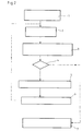
- FIG. 2 A flow diagram shown in FIG. 2 indicates the process steps in the form of flow blocks:
Landscapes
- Engineering & Computer Science (AREA)
- Computing Systems (AREA)
- Theoretical Computer Science (AREA)
- Human Computer Interaction (AREA)
- Manufacturing & Machinery (AREA)
- Physics & Mathematics (AREA)
- General Physics & Mathematics (AREA)
- Automation & Control Theory (AREA)
- Numerical Control (AREA)
Description
Die Erfindung betrifft ein Verfahren zur Ermittlung von Werkzeugbahn-Konturen bei numerisch gesteuerten Maschinen gemäß dem Oberbegriff des Anspruchs 1.The invention relates to a method for determining tool path contours in numerically controlled machines according to the preamble of claim 1.
Aus der Druckschrift US-A- 3 629 558 ist ein Verfahren für die Bearbeitung von Werkstücken bekannt, das offenbart, gekrümmte Konturen eines Werkstückes abschnittsweise zu linearisieren.From the document US-A-3 629 558 a method for machining workpieces is known which discloses linearizing curved contours of a workpiece in sections.
Bei numerisch gesteuerten Werkzeugmaschinen ist es allgemein bekannt, die Daten für die Herstellung eines Werkstückes aus einem Werkstücksrohling in Form von Werkzeugbahn-Daten durch ein NC-Programm zu bestimmen. Dazu ist erforderlich, die Kontur des herzustellenden Werkstückes mit dem Werkzeugradius zu korrigieren, dafürdie Maschine nicht die Werkstückkontur, sondern die Werkzeugmittelpunkt-Bahn relevant ist.In numerically controlled machine tools, it is generally known to determine the data for the production of a workpiece from a workpiece blank in the form of tool path data by means of an NC program. To do this, it is necessary to correct the contour of the workpiece to be manufactured with the tool radius, for which the machine is not the workpiece contour, but the tool center path is relevant.
Für NC-Steuerungen ist das Berechnen der korrigierten Schnittkontur eines beliebigen Körpers eine komplexe und rechenintensive Aufgabe.For NC controls, calculating the corrected cutting contour of any body is a complex and computationally intensive task.
Die Schwierigkeiten liegen hier schon in der Definition eines komplexen Körpers und seiner Oberfläche und dann in der Berechnung einer Äquidistanten für die Fräserradiuskorrektur unter Berücksichtigung möglicher Kollisionen bei vorgegebener Genauigkeit. Entsprechend hoch ist der erforderliche Einsatz an Rechenkapazität und Speicherkapazität. Um solche Berechnungen durchzuführen, ist auf dem Rechner der NC-Steuerung zusätzliche Hard- und Software notwendig. Dazu gehören beispielsweise spezielle Arithmetikprozessoren, aber auch geometrische Verfahren und Darstellungsmethoden zur Beschreibung von Freiformflächen.The difficulties here already lie in the definition of a complex body and its surface and then in the calculation of an equidistant for the cutter radius correction, taking into account possible collisions with a given accuracy. The required use of computing capacity and storage capacity is correspondingly high. To carry out such calculations, additional hardware and software are required on the computer of the NC control. These include, for example, special arithmetic processors, but also geometric methods and display methods for describing free-form surfaces.
Relativ komplexe Körperkonturen lassen sich aus einfachen Konturstücken wie Kreisen und Geraden zusammenstellen. Die Werkzeugradiuskorrekturen lassen sich an diesen einfachen Konturen leichtdurchführen, jedoch ist es problematisch, aus den einzelnen korrigierten Konturen die resultierende Werkzeugbahn zu ermitteln, da es bei den einzeln korrigierten Konturen durch deren Zusammenfassung zu Überschneidungen kommt.Relatively complex body contours can be put together from simple contour pieces such as circles and straight lines. The tool radius corrections can easily be carried out on these simple contours, but it is problematic to determine the resulting tool path from the individual corrected contours, since the individually corrected contours overlap when combined.
Um die Ermittlung der Werkzeugbahn-Konturen bzw. deren Bahndaten zu vereinfachen, wird bereits an einer einfachen 2d-Kontur eine Fräserbahnkorrektur vorgenommen. Diese Werkzeugbahn-Kontur bildet eine korrigierte 2d-Kontur. Die korrigierte 2d-Kontur wird entlang eines Vektors beispielsweise translatorisch verschoben und auf diese Weise ein korrigiertes 3d-Objekt gebildet. Die Oberflächen eines korrigierten Körpers beschreiben äquidistante Flächen zu den Oberflächen des Grundkörpers.In order to simplify the determination of the tool path contours and their path data, a milling path correction is already carried out on a simple 2d contour. This tool path contour forms a corrected 2d contour. The corrected 2d contour is shifted translationally along a vector, for example, and a corrected 3d object is formed in this way. The surfaces of a corrected body describe equidistant surfaces to the surfaces of the base body.
Die Zusammensetzung der gewünschten Körper zum herzustellenden Werkstück erfolgt anhand der bereits korrigierten Körper, so daß die Werkzeugbahn-Konturen sich mit den Schnittlinien eines zusammengesetzten - bereits korrigierten - Gesamtkörpers decken.The composition of the desired body to the workpiece to be produced takes place on the basis of the already corrected body, so that the tool path contours coincide with the cutting lines of an assembled - already corrected - whole body.
Nun werden die Schnittlinien zwischen den korrigierten Oberflächen und der jeweiligen Bearbeitungsebene berechnet. Dies sind bei Translationskörpern Geradenabschnitte und bei Rotationskörpern die Kurven von allgemeinen Kegel- bzw. Zylinderschnitten.Now the cutting lines between the corrected surfaces and the respective working plane are calculated. These are straight sections for translational bodies and the curves of general conical or cylindrical sections for rotating bodies.
Der Erfindung liegt die Aufgabe zugrunde, die Bearbeitung dieser allgemeinen Kurven zu vereinfachen.The invention has for its object to simplify the processing of these general curves.
Diese Aufgabe wird durch ein Verfahren mit den Merkmalen des Anspruches 1 gelöst.This object is achieved by a method having the features of claim 1.
Die Vorteile des erfindungsgemäßen Verfahrens liegen darin, daß die Folge der erzeugten Kurven linearisiert wird, und zwar unter Berücksichtigung der durch die Maschine vorgegebenen Auflösung.The advantages of the method according to the invention are that the sequence of the curves generated is linearized, taking into account the resolution specified by the machine.
Ist z. B. eine Kurve zweiter Ordnung (Kegelschnitt) gegeben (y2 = al . X 2 + a2 x + a3), dann wird diese durch eine Folge von Geradenabschnitte angenähert. Um die Schrittweite (die Länge eines Interpolationsintervalls oder auch Linearisierungs-Abschnittes)
- a) nicht von vorn herein und
- b) nicht für die ganze Kurve
festlegen zu müssen, wurde das erfindungsgemäße Verfahren entwickelt, das ohne diese Voraussetzungen auskommt.
- a) not from the beginning and
- b) not for the whole curve
The method according to the invention was developed which does not have to meet these requirements.
In besonders vorteilhafter Weise ist dazu ein Verfahren geeignet, mit dem in Abhängigkeit von der tatsächlichen Krümmung der Kurve eine Interpolation mit 3d-Geradenabschnitten erzeugt wird, wodurch Linearisierungs-Abschnitte entstehen. Dadurch ist gewährleistet, daß immer nur soviele Linearisierungs-Abschnitte erzeugt werden, wie zur Einhaltung des maximalen Fehlers notwendig sind, was zu einer starken Reduktion der Datenmengen und somit zur Einsparung von Speicherplatz führt.In a particularly advantageous manner, a method is suitable for this, with which, depending on the actual curvature of the curve, an interpolation with 3d straight-line sections is generated, which results in linearization sections. This ensures that only as many linearization sections are generated as are necessary to maintain the maximum error, which leads to a large reduction in the amount of data and thus to a saving of storage space.
Die Folge der auf diese Art und Weise berechneten Linearisierungs-Abschnitte ergibt die korrigierte Schnittkontur.The sequence of the linearization sections calculated in this way results in the corrected cutting contour.
Dieses Verfahren wird nachstehend anhand der Figuren 1A und 1 B beschrieben.This method is described below with reference to FIGS. 1A and 1B.
Es zeigt
- Figur 1A eine Fräserbahn-Kontur;
- Figur 1 B einen vergrößerten Abschnitt der Fräserbahn-Kontur und
Figur 2 ein Flußdiagramm.
- FIG. 1A shows a milling cutter contour;
- Figure 1 B shows an enlarged portion of the milling path contour
- Figure 2 is a flow chart.
In Figur 1A ist ein gekrümmter Verlauf einer Kontur K gezeigt, der gemäß dem Stand der Technik durch Geradenabschnitte (ki (i = 0 ... n)) eines fest vorgegebenen Rasters angenähert von der Fräsmaschine erzeugt wird. Da die Weite der Geradenabschnitte festliegt, nimmt die Abweichung der tatsächlich erzeugten Kontur von der gewünschten bzw. idealen Kontur K mit zunehmender Krümmung dieser Kontur K zu.FIG. 1A shows a curved course of a contour K which, according to the prior art, is generated approximately by the milling machine by straight line sections (ki (i = 0 ... n)) of a predetermined grid. Since the width of the straight line sections is fixed, the deviation of the actually generated contour from the desired or ideal contour K increases with increasing curvature of this contour K.
Besonders deutlich wird dies durch die übertriebene Darstellung in Figur 1 B. Dort ist ein Ausschnitt der Kontur K aus Figur 1 A gezeigt.This is particularly clear from the exaggerated representation in FIG. 1B. A section of the contour K from FIG. 1A is shown there.
Die Kontur K wird mit Geradenabschnitten erzeugt, von denen hier nur der Abschnitt Ki dargestellt ist. Ein nicht dargestellter Fräser würde auf diesem Abschnitt Ki die Punkte P1 und P2 der Kontur K durch seine Fräserbahn verbinden.The contour K is generated with straight sections, of which only the section Ki is shown here. A milling cutter (not shown) would connect the points P1 and P2 of the contour K on this section Ki through its milling track.
Das Verfahren kann die vorstehend definierten Kurven K mit beliebiger Genauigkeit interpolieren. Die Genauigkeit wird durch eine skalare Größe vorgegeben und gibt die maximale Abweichung eines Geradenabschnitts von der Kurve K an.The method can interpolate the curves K defined above with any accuracy. The accuracy is specified by a scalar quantity and specifies the maximum deviation of a line segment from the curve K.
Die maximale Abweichung ist dabei definiert, als die Länge des Lotes (d), die sich aus dem Schnitt des Lotes (d) von der Interpolationsgeraden zwischen P1 und P2 mit der Kurve K selbst und der Interpolationsgeraden Ki ergibt (Figur 1 B).The maximum deviation is defined as the length of the solder (d), which results from the intersection of the solder (d) from the interpolation line between P1 and P2 with the curve K itself and the interpolation line Ki (FIG. 1B).
Um die Annäherung an die gewünschte Kontur K zu verbessern, wird also das Lot von dem Geradenabschnitt Ki auf die Kontur K gefällt und der Ort der größten Abweichung festgestellt. Der Schnittpunkt der Kontur K mit dem Lot bestimmt einen Punkt P3.In order to improve the approximation to the desired contour K, the solder is thus dropped from the straight section Ki onto the contour K and the location of the greatest deviation is determined. The intersection of the contour K with the plumb line determines a point P3.
Die Schrittweite wird in vorteilhafter Weise dynamisch bestimmt, d. h. die Anzahl der Linearisierungs-Abschnitte hängt von den konkreten Eigenschaften der Kurve K ab, d. h. der Kurvenparameter (a1, a2, a3).The step size is advantageously determined dynamically, i. H. the number of linearization sections depends on the specific properties of curve K, i. H. the curve parameters (a1, a2, a3).
Die NC-Steuerung, mit deren Hilfe der Punkt P3 ermittelt wurde, legt als neue Linearisierungs-Abschnitte die Geraden Kj und Kk fest, mit denen die Punkte P1 und P3 sowie P3 und P2 verbunden werden. Es zeigt sich, daß die sogenannte Linearisierung durch die neuen Geraden Kj und Kk schon deutlich bessere Annäherung an die Kontur K gebracht hat.The NC control, with the aid of which point P3 was determined, defines the straight lines Kj and Kk as new linearization sections, with which the points P1 and P3 as well as P3 and P2 are connected. It can be seen that the so-called linearization by the new straight lines Kj and Kk has brought the contour K much better.
Wenn die gleiche Verfahrensweise auch an dem neuen Linearisierungs-Abschnitt Kk durchgeführt wird, nähern sich die dadurch erzeugten weiteren Linearisierungs-Abschnitte KI und Km schon sehr stark an den realen Konturenverlauf K an. Es ist ersichtlich, daß mit diesem Verfahren zur krümmungsabhängigen Linearisierung auch die Linearisierungs-Abschnitts-Länge krümmungsabhängig wird. Mit diesem Verfahren wird die Bahn des Fräsers an die Idealkontur in höchstem Maße angeglichen.If the same procedure is also carried out on the new linearization section Kk, the further linearization sections KI and Km generated thereby approach the real contour profile K very closely. It can be seen that this method for curvature-dependent linearization also makes the linearization section length dependent on curvature. With this process, the path of the milling cutter is matched to the ideal contour to the highest degree.
Durch Verwendung dieses rekursiven Algorithmus, der die Eigenheiten der Problemstellung ausnutzt, wird der Verwaltungs- und Speicheraufwand bei der Erzeugung der interpolierenden Linearisierungs-Abschnitte optimiert.By using this recursive algorithm, which takes advantage of the peculiarities of the problem, the administration and storage effort in the generation of the interpolating linearization sections is optimized.
Das Verfahren zeichnet sich durch eine schnelle Konvergenz auf die Lösung aus, da die Interpolation automatisch in den Bereich der Kurve K wandert, der am stärksten gekrümmt ist, und somit die meisten Linearisierungs-Abschnitte zur Interpolation erfordert.The method is characterized by a rapid convergence to the solution, since the interpolation automatically moves into the region of the curve K which is the most curved and therefore requires the most linearization sections for interpolation.
Ein in Figur 2 dargestelltes Flußdiagramm gibt die Verfahrensschritte in Form von Ablaufblöcken an:A flow diagram shown in FIG. 2 indicates the process steps in the form of flow blocks:
Zuerst werden gemäß 1 die Parameter der Kurve K und des Interpolationsintervalles Ko = [Po, Po'] aufgenommen. Anschließend werden die Daten des aktuellen Intervalles nach 2 übergeben. Gemäß Figur 1 B sind dies das Intervall Ki mit den Anfangs- und Endpunkten P1 und P2. Im Schritt 3 wird die maximale Abweichung in dem aktuellen Intervall Ki errechnet und der Schnittpunkt des Lotes d mit der Kurve K ermittelt. Die Koordinaten des neuen Punktes P3 (Schnittpunkt Lot d / Kurve K) werden bestimmt.1, the parameters of the curve K and the interpolation interval Ko = [Po, Po '] are recorded. The data of the current interval after 2 are then transferred. According to FIG. 1B, these are the interval Ki with the start and end points P1 and P2. In step 3, the maximum deviation in the current interval Ki is calculated and the intersection of the solder d with the curve K is determined. The coordinates of the new point P3 (intersection Lot d / curve K) are determined.
Anschließend wird in Schritt 4 die Entscheidung getroffen, ob die maximale Abweichung (Lot d) kleiner ist als ein vorbestimmbarer Grenzwert. Ist der Betrag des Lotes d kleiner als dieser Grenzwert, dann ist das aktuelle Intervall Ki zulässig, und seine Anfangs- und Endpunkte P1 und P2 sind zulässige Punkte der Geraden Ki; der Fräser kann somit diese Punkte P1 und P2 anfahren.The decision is then made in step 4 as to whether the maximum deviation (Lot d) is less than a predeterminable limit value. If the amount of the solder d is less than this limit value, the current interval Ki is permissible and its start and end points P1 and P2 are permissible points on the straight line Ki; the milling cutter can thus approach these points P1 and P2.
Ergibt der Vergleich für die Entscheidung, daß die Abweichung (Lot d) größer ist, als der Grenzwert, so werden gemäß 5 zwei neue Intervalle Kj bzw. Kk definiert, deren Anfangs- und Endpunkte P1 und P3 bzw. P3 und P2 sind.If the comparison for the decision shows that the deviation (Lot d) is greater than the limit value, two new intervals Kj and Kk are defined according to FIG. 5, the start and end points of which are P1 and P3 or P3 and P2.
Im Schritt 6 wird nun der vorbeschriebene Algorithmus auf das "linke" Intervall Kj und das "rechte" Intervall Kk angewendet u.s.w..In
Durch diese rekursive Anwendung des Verfahrens entstehen gemäß Figur 1 B weitere Intervalle KI und Km, bis daß die Kurve K genügend angenähert ist.This recursive application of the method results in further intervals KI and Km according to FIG. 1B until the curve K is sufficiently approximated.
Claims (2)
Priority Applications (6)
| Application Number | Priority Date | Filing Date | Title |
|---|---|---|---|
| ES90118384T ES2083409T3 (en) | 1990-09-25 | 1990-09-25 | PROCEDURE TO DETERMINE THE CONTOUR OF PATH OF TOOLS FOR NUMERICAL CONTROL MACHINES. |
| DE59009901T DE59009901D1 (en) | 1990-09-25 | 1990-09-25 | Procedure for determining tool path contours in numerically controlled machines. |
| EP90118384A EP0477397B2 (en) | 1990-09-25 | 1990-09-25 | Method to determine the contour of the machine tool path by a numerically controlled machine |
| DE4037967A DE4037967A1 (en) | 1990-09-25 | 1990-11-29 | METHOD FOR DETERMINING TOOL PATH CONTOURS IN NUMERICALLY CONTROLLED MACHINES |
| JP3243706A JP2875656B2 (en) | 1990-09-25 | 1991-09-24 | A method for determining the tool trajectory contour in numerically controlled machines |
| US07/765,127 US5434793A (en) | 1990-09-25 | 1991-09-25 | Method and apparatus for ascertaining tool path contours approximating curved contour intersection lines in numerically controlled machines |
Applications Claiming Priority (1)
| Application Number | Priority Date | Filing Date | Title |
|---|---|---|---|
| EP90118384A EP0477397B2 (en) | 1990-09-25 | 1990-09-25 | Method to determine the contour of the machine tool path by a numerically controlled machine |
Publications (3)
| Publication Number | Publication Date |
|---|---|
| EP0477397A1 EP0477397A1 (en) | 1992-04-01 |
| EP0477397B1 true EP0477397B1 (en) | 1995-11-22 |
| EP0477397B2 EP0477397B2 (en) | 1999-09-01 |
Family
ID=8204510
Family Applications (1)
| Application Number | Title | Priority Date | Filing Date |
|---|---|---|---|
| EP90118384A Expired - Lifetime EP0477397B2 (en) | 1990-09-25 | 1990-09-25 | Method to determine the contour of the machine tool path by a numerically controlled machine |
Country Status (5)
| Country | Link |
|---|---|
| US (1) | US5434793A (en) |
| EP (1) | EP0477397B2 (en) |
| JP (1) | JP2875656B2 (en) |
| DE (2) | DE59009901D1 (en) |
| ES (1) | ES2083409T3 (en) |
Cited By (1)
| Publication number | Priority date | Publication date | Assignee | Title |
|---|---|---|---|---|
| CN108536093A (en) * | 2018-04-09 | 2018-09-14 | 枣庄北航机床创新研究院有限公司 | The processing method of non-rotating type tool Complex Surface in NC Machining |
Families Citing this family (17)
| Publication number | Priority date | Publication date | Assignee | Title |
|---|---|---|---|---|
| JP3242162B2 (en) * | 1992-08-21 | 2001-12-25 | 日本板硝子株式会社 | NC processing method |
| DE19602470A1 (en) * | 1996-01-24 | 1997-07-31 | Siemens Ag | Determination and optimization of the working accuracy of a machine tool or a robot or the like |
| JPH09269808A (en) * | 1996-03-29 | 1997-10-14 | Fanuc Ltd | Cnc data correcting method |
| US6922606B1 (en) | 1999-11-19 | 2005-07-26 | Siemens Energy & Automation, Inc. | Apparatus and method for smooth cornering in a motion control system |
| US7870354B2 (en) | 2003-11-04 | 2011-01-11 | Bakbone Software, Inc. | Data replication from one-to-one or one-to-many heterogeneous devices |
| EP1680742A2 (en) | 2003-11-04 | 2006-07-19 | Constant Data, Inc. | Hybrid real-time data replication |
| AU2007234833B2 (en) * | 2006-04-05 | 2010-03-25 | Saint-Gobain Ceramics & Plastics, Inc. | A SOFC stack having a high temperature bonded ceramic interconnect and method for making same |
| JP5202735B2 (en) * | 2009-06-03 | 2013-06-05 | 三菱電機株式会社 | Numerical controller |
| CN102880118B (en) * | 2012-09-27 | 2014-08-06 | 中国科学院数学与系统科学研究院 | Method for interpolating curve with variable interpolation cycle on basis of interpolation precision and limitation of accelerations |
| CN103777572B (en) * | 2014-02-25 | 2016-01-13 | 大连理工大学 | A Fast Segmentation Method for Complex Surface Models with Sudden Features |
| CN106033214B (en) * | 2015-03-19 | 2018-11-06 | 宁夏巨能机器人系统有限公司 | A kind of cutter feeding control device and its control method of numerically-controlled machine tool |
| CN104991522B (en) * | 2015-04-23 | 2018-01-16 | 北京第二机床厂有限公司 | Profile transition method based on cloudy cam corase grind |
| EP3125055A1 (en) * | 2015-07-31 | 2017-02-01 | Siemens Aktiengesellschaft | Tool guiding method joints for adjacent surfaces |
| CN107976688A (en) * | 2016-10-25 | 2018-05-01 | 菜鸟智能物流控股有限公司 | Obstacle detection method and related device |
| CN112222497B (en) * | 2020-10-21 | 2022-09-13 | 一重集团大连核电石化有限公司 | Method for processing large conical adapter space curved surface on three-axis linkage milling machine |
| CN112650147B (en) * | 2020-12-28 | 2023-11-28 | 深圳数马电子技术有限公司 | Maximum speed parameter limiting method and device under curvature limitation |
| CN116551457B (en) * | 2023-07-11 | 2023-10-27 | 济南邦德激光股份有限公司 | Method and equipment for connecting and processing straight line segment and circular arc segment through spline curve |
Family Cites Families (41)
| Publication number | Priority date | Publication date | Assignee | Title |
|---|---|---|---|---|
| US3634661A (en) * | 1968-09-26 | 1972-01-11 | Giddings & Lewis | Data processing method for minimizing potential errors occurring during linear and circular interpolation |
| GB1319286A (en) * | 1969-06-21 | 1973-06-06 | Olivetti & Co Spa | Numerical control device |
| US3629558A (en) * | 1969-09-12 | 1971-12-21 | Bendix Corp | Method for preparing control tapes |
| US3757095A (en) * | 1970-08-26 | 1973-09-04 | Tektronix Inc | Numerical control system |
| US3767990A (en) * | 1972-02-09 | 1973-10-23 | Bridgeport Machines | Control system for producing multi-axis contour movement for a stepping motor drive |
| US3927948A (en) * | 1972-06-15 | 1975-12-23 | Leonard C Cox | Apparatus for producing data indicative of the geometric shape and arrangement of the various components of a model |
| US3860805A (en) * | 1973-05-07 | 1975-01-14 | Bendix Corp | Method and apparatus for producing a fairing contour in numerical control systems |
| US3969615A (en) * | 1974-12-20 | 1976-07-13 | The United States Of America As Represented By The United States Energy Research And Development Administration | Interpolator for numerically controlled machine tools |
| US4031369A (en) * | 1975-08-12 | 1977-06-21 | The Bendix Corporation | Interpolation and control apparatus and method for a numerical control system |
| US4127849A (en) * | 1975-11-03 | 1978-11-28 | Okor Joseph K | System for converting coded data into display data |
| US4275449A (en) * | 1978-04-28 | 1981-06-23 | National Research Development Corporation | Modelling arrangements |
| JPS584377A (en) * | 1981-03-18 | 1983-01-11 | 株式会社安川電機 | Controller for articulated industrial robot |
| DE3113970A1 (en) * | 1981-04-07 | 1982-11-04 | Dr. Johannes Heidenhain Gmbh, 8225 Traunreut | NUMERICAL PATTERN CONTROL FOR A MACHINE TOOL |
| EP0075792B1 (en) * | 1981-09-24 | 1987-08-26 | Hitachi, Ltd. | Control system for robot hand |
| JPS5882310A (en) * | 1981-11-12 | 1983-05-17 | Fanuc Ltd | Numerical controlling with position display function |
| US4581698A (en) * | 1981-11-18 | 1986-04-08 | General Electric Company | Method and system for generating interpolation pulses |
| EP0088503A3 (en) * | 1982-02-17 | 1986-02-26 | Imperial Chemical Industries Plc | Photogrammetric computer aided method for plant construction |
| US4704685A (en) * | 1982-04-09 | 1987-11-03 | Motorola, Inc. | Failsafe engine fuel control system |
| US4536848A (en) * | 1982-04-15 | 1985-08-20 | Polaroid Corporation | Method and apparatus for colored computer graphic photography |
| US4506335A (en) * | 1982-06-10 | 1985-03-19 | Cincinnati Milacron Inc. | Manipulator with controlled path motion |
| US4551810B1 (en) * | 1982-07-28 | 1995-09-05 | Technology Inc Const | Method and apparatus for designing duct work for producing patterns for conduit sections in the designated duct work |
| JPS59140513A (en) * | 1983-01-31 | 1984-08-11 | Fanuc Ltd | Color graphic display device for nc |
| JPS59158409A (en) * | 1983-03-01 | 1984-09-07 | Mitsubishi Electric Corp | Numerical controller |
| DE3311119C2 (en) * | 1983-03-26 | 1986-12-04 | Dr. Johannes Heidenhain Gmbh, 8225 Traunreut | Method for returning a tool to a workpiece contour |
| GB2140937A (en) * | 1983-05-10 | 1984-12-05 | Philips Nv | Simulation of machine tools |
| DE3338765C2 (en) * | 1983-10-26 | 1986-01-30 | Dr. Johannes Heidenhain Gmbh, 8225 Traunreut | Circuit arrangement for the representation of changeable structures |
| JPS60107106A (en) * | 1983-11-15 | 1985-06-12 | Mitsubishi Electric Corp | Curve interpolation system |
| DE3401060A1 (en) * | 1984-01-13 | 1986-01-23 | Dr. Johannes Heidenhain Gmbh, 8225 Traunreut | METHOD FOR PRESENTING AN IMAGE |
| DE3403677A1 (en) * | 1984-02-03 | 1985-08-08 | Dr. Johannes Heidenhain Gmbh, 8225 Traunreut | METHOD FOR PRODUCING WORKPIECE CONTOURS |
| DE3608438A1 (en) * | 1985-03-13 | 1986-09-18 | Toshiba Kikai K.K., Tokio/Tokyo | METHOD FOR CALCULATING FREE CURVED SURFACES BY MEANS OF COMPUTER-AID DESIGN CAD AND COMPUTER-AID MANUFACTURING CAM AND NUMERICAL CONTROL NC |
| JPH061406B2 (en) * | 1985-09-05 | 1994-01-05 | 松下電器産業株式会社 | Method of teaching a moving body route |
| JPH061404B2 (en) * | 1985-09-13 | 1994-01-05 | フアナツク株式会社 | Complex curved surface processing method |
| DE3616740A1 (en) * | 1986-05-17 | 1987-11-19 | Heidenhain Gmbh Dr Johannes | DEVICE FOR OBTAINING WORKPIECE CONTOURS |
| DE3640987C1 (en) * | 1986-12-01 | 1993-04-29 | Agie Ag Ind Elektronik | Numerical control system for highly dynamic processes |
| DE3716704C1 (en) * | 1987-05-19 | 1988-11-17 | Afs Entwicklungs & Vertriebs G | Control circuit for controlling a knife |
| US4833617A (en) * | 1987-08-14 | 1989-05-23 | General Electric Company | Solid modeling based adaptive feedrate control for NC machining |
| JPH02146607A (en) * | 1988-11-29 | 1990-06-05 | Fanuc Ltd | Interpolation system for nc transfer command |
| JP2619532B2 (en) * | 1989-06-28 | 1997-06-11 | ファナック株式会社 | Involute interpolation error correction method |
| JPH0354610A (en) * | 1989-07-21 | 1991-03-08 | Fanuc Ltd | Involute interpolation error correcting system |
| US5229698A (en) * | 1990-08-06 | 1993-07-20 | Cincinnati Milacron Inc. | Method and apparatus for sub-span interpolation |
| EP0495147A1 (en) * | 1991-01-18 | 1992-07-22 | Siemens Aktiengesellschaft | Method for path correction in numerical controlled machines |
-
1990
- 1990-09-25 EP EP90118384A patent/EP0477397B2/en not_active Expired - Lifetime
- 1990-09-25 DE DE59009901T patent/DE59009901D1/en not_active Expired - Fee Related
- 1990-09-25 ES ES90118384T patent/ES2083409T3/en not_active Expired - Lifetime
- 1990-11-29 DE DE4037967A patent/DE4037967A1/en not_active Withdrawn
-
1991
- 1991-09-24 JP JP3243706A patent/JP2875656B2/en not_active Expired - Lifetime
- 1991-09-25 US US07/765,127 patent/US5434793A/en not_active Expired - Fee Related
Cited By (2)
| Publication number | Priority date | Publication date | Assignee | Title |
|---|---|---|---|---|
| CN108536093A (en) * | 2018-04-09 | 2018-09-14 | 枣庄北航机床创新研究院有限公司 | The processing method of non-rotating type tool Complex Surface in NC Machining |
| CN108536093B (en) * | 2018-04-09 | 2020-04-03 | 枣庄北航机床创新研究院有限公司 | Machining method of NC machining of complex curved surfaces with non-rotational tools |
Also Published As
| Publication number | Publication date |
|---|---|
| US5434793A (en) | 1995-07-18 |
| JPH04230503A (en) | 1992-08-19 |
| DE59009901D1 (en) | 1996-01-04 |
| EP0477397A1 (en) | 1992-04-01 |
| DE4037967A1 (en) | 1992-03-26 |
| ES2083409T3 (en) | 1996-04-16 |
| JP2875656B2 (en) | 1999-03-31 |
| EP0477397B2 (en) | 1999-09-01 |
Similar Documents
| Publication | Publication Date | Title |
|---|---|---|
| EP0477397B2 (en) | Method to determine the contour of the machine tool path by a numerically controlled machine | |
| EP0290374B1 (en) | Method of and device for generating and reproducing two-dimensional graphical objects | |
| EP0384925B1 (en) | Control method for a digital machine tool or a robot | |
| EP0246422B1 (en) | Apparatus for determining the contours of a work piece | |
| DE19618332A1 (en) | Spline interpolation function for numerical control | |
| EP0134910B1 (en) | Method of spark-erosion cutting of a falling out part of a working part provided with parallel surfaces | |
| EP0151274B1 (en) | Method for representing objects | |
| DE10085460B4 (en) | Electric discharge machining method and apparatus | |
| EP0477398B1 (en) | Method to machine workpieces with a numerical controlled machine | |
| DE2045114A1 (en) | Process for the production of data sets for numerical controls | |
| DE3243708A1 (en) | MACHINING CONTROL METHOD FOR MILLING | |
| DE3820566C2 (en) | Method for determining a path of movement of a machining tool of a machine tool controlled by a numerical control device | |
| CH679022A5 (en) | ||
| DE3688193T2 (en) | METHOD FOR FORMING A COMPOSITE-CURVED SURFACE. | |
| WO2020094560A1 (en) | Method for calculating optimized machine-readable cutting curves for a laser cutting device | |
| DE102018117244B3 (en) | Method for determining a rough path from a predetermined contour | |
| DE2632278A1 (en) | INTERPOLATOR FOR A NUMERICALLY CONTROLLED MACHINE | |
| DE4323572B4 (en) | Method for determining a tool path in an NC system | |
| DE3700887C2 (en) | ||
| EP0836128B1 (en) | Control method for motion operation in a numerically controlled industrial machining apparatus | |
| EP0932467A1 (en) | Machining method for three-dimensional connecting surfaces | |
| DE2226547A1 (en) | Proportional interpolator for multi-axis machines | |
| DE4430003A1 (en) | Numerical displacement control method for automatic machine tool | |
| DE2418360B2 (en) | NUMERICAL TOOL CORRECTION IN A MACHINE TOOL CONTROL | |
| DE3788613T2 (en) | METHOD FOR PRODUCING NUMERICAL DATA OF A CURVED COMPOSITE SURFACE. |
Legal Events
| Date | Code | Title | Description |
|---|---|---|---|
| PUAI | Public reference made under article 153(3) epc to a published international application that has entered the european phase |
Free format text: ORIGINAL CODE: 0009012 |
|
| 17P | Request for examination filed |
Effective date: 19901015 |
|
| AK | Designated contracting states |
Kind code of ref document: A1 Designated state(s): AT CH DE ES FR GB IT LI NL SE |
|
| 17Q | First examination report despatched |
Effective date: 19931217 |
|
| ITF | It: translation for a ep patent filed | ||
| GRAA | (expected) grant |
Free format text: ORIGINAL CODE: 0009210 |
|
| AK | Designated contracting states |
Kind code of ref document: B1 Designated state(s): CH DE FR GB LI |
|
| ET | Fr: translation filed | ||
| GBT | Gb: translation of ep patent filed (gb section 77(6)(a)/1977) |
Effective date: 19951117 |
|
| REF | Corresponds to: |
Ref document number: 59009901 Country of ref document: DE Date of ref document: 19960104 |
|
| REG | Reference to a national code |
Ref country code: CH Ref legal event code: NV Representative=s name: TROESCH SCHEIDEGGER WERNER AG |
|
| REG | Reference to a national code |
Ref country code: ES Ref legal event code: FG2A Ref document number: 2083409 Country of ref document: ES Kind code of ref document: T3 |
|
| PLBI | Opposition filed |
Free format text: ORIGINAL CODE: 0009260 |
|
| 26 | Opposition filed |
Opponent name: SIEMENS AG Effective date: 19960806 |
|
| PLBF | Reply of patent proprietor to notice(s) of opposition |
Free format text: ORIGINAL CODE: EPIDOS OBSO |
|
| PLBF | Reply of patent proprietor to notice(s) of opposition |
Free format text: ORIGINAL CODE: EPIDOS OBSO |
|
| PLAW | Interlocutory decision in opposition |
Free format text: ORIGINAL CODE: EPIDOS IDOP |
|
| PLAW | Interlocutory decision in opposition |
Free format text: ORIGINAL CODE: EPIDOS IDOP |
|
| PGFP | Annual fee paid to national office [announced via postgrant information from national office to epo] |
Ref country code: ES Payment date: 19980925 Year of fee payment: 9 |
|
| PUAH | Patent maintained in amended form |
Free format text: ORIGINAL CODE: 0009272 |
|
| STAA | Information on the status of an ep patent application or granted ep patent |
Free format text: STATUS: PATENT MAINTAINED AS AMENDED |
|
| RBV | Designated contracting states (corrected) |
Designated state(s): CH DE FR GB LI |
|
| 27A | Patent maintained in amended form |
Effective date: 19990901 |
|
| AK | Designated contracting states |
Kind code of ref document: B2 Designated state(s): CH DE FR GB LI |
|
| ET3 | Fr: translation filed ** decision concerning opposition | ||
| GBTA | Gb: translation of amended ep patent filed (gb section 77(6)(b)/1977) | ||
| REG | Reference to a national code |
Ref country code: CH Ref legal event code: AEN Free format text: AUFRECHTERHALTUNG DES PATENTES IN GEAENDERTER FORM |
|
| PGFP | Annual fee paid to national office [announced via postgrant information from national office to epo] |
Ref country code: GB Payment date: 20000814 Year of fee payment: 11 |
|
| PGFP | Annual fee paid to national office [announced via postgrant information from national office to epo] |
Ref country code: CH Payment date: 20000816 Year of fee payment: 11 |
|
| PGFP | Annual fee paid to national office [announced via postgrant information from national office to epo] |
Ref country code: FR Payment date: 20000831 Year of fee payment: 11 |
|
| PG25 | Lapsed in a contracting state [announced via postgrant information from national office to epo] |
Ref country code: GB Free format text: LAPSE BECAUSE OF NON-PAYMENT OF DUE FEES Effective date: 20010925 |
|
| PG25 | Lapsed in a contracting state [announced via postgrant information from national office to epo] |
Ref country code: LI Free format text: LAPSE BECAUSE OF NON-PAYMENT OF DUE FEES Effective date: 20010930 Ref country code: CH Free format text: LAPSE BECAUSE OF NON-PAYMENT OF DUE FEES Effective date: 20010930 |
|
| REG | Reference to a national code |
Ref country code: GB Ref legal event code: IF02 |
|
| GBPC | Gb: european patent ceased through non-payment of renewal fee |
Effective date: 20010925 |
|
| REG | Reference to a national code |
Ref country code: CH Ref legal event code: PL |
|
| PG25 | Lapsed in a contracting state [announced via postgrant information from national office to epo] |
Ref country code: FR Free format text: LAPSE BECAUSE OF NON-PAYMENT OF DUE FEES Effective date: 20020531 |
|
| REG | Reference to a national code |
Ref country code: FR Ref legal event code: ST |
|
| REG | Reference to a national code |
Ref country code: ES Ref legal event code: FD2A Effective date: 20001013 |
|
| PGFP | Annual fee paid to national office [announced via postgrant information from national office to epo] |
Ref country code: DE Payment date: 20050912 Year of fee payment: 16 |
|
| PG25 | Lapsed in a contracting state [announced via postgrant information from national office to epo] |
Ref country code: DE Free format text: LAPSE BECAUSE OF NON-PAYMENT OF DUE FEES Effective date: 20070403 |