EP0477085A1 - Vorrichtung zur Ausführung von Zug- und Druck-Tests an Proben nach Atmosphärenwiedereintrittssimulation - Google Patents
Vorrichtung zur Ausführung von Zug- und Druck-Tests an Proben nach Atmosphärenwiedereintrittssimulation Download PDFInfo
- Publication number
- EP0477085A1 EP0477085A1 EP91402463A EP91402463A EP0477085A1 EP 0477085 A1 EP0477085 A1 EP 0477085A1 EP 91402463 A EP91402463 A EP 91402463A EP 91402463 A EP91402463 A EP 91402463A EP 0477085 A1 EP0477085 A1 EP 0477085A1
- Authority
- EP
- European Patent Office
- Prior art keywords
- test piece
- jaws
- jaw
- tensile
- test
- Prior art date
- Legal status (The legal status is an assumption and is not a legal conclusion. Google has not performed a legal analysis and makes no representation as to the accuracy of the status listed.)
- Withdrawn
Links
- 238000012360 testing method Methods 0.000 title claims abstract description 39
- 238000004088 simulation Methods 0.000 title description 5
- 241001272720 Medialuna californiensis Species 0.000 claims abstract description 5
- 239000008188 pellet Substances 0.000 claims abstract description 4
- 238000009864 tensile test Methods 0.000 claims description 14
- 238000012669 compression test Methods 0.000 claims description 10
- 238000003754 machining Methods 0.000 claims description 3
- 239000000463 material Substances 0.000 description 3
- 241000030366 Scorpidinae Species 0.000 description 1
- 230000001944 accentuation Effects 0.000 description 1
- 230000015556 catabolic process Effects 0.000 description 1
- 230000006835 compression Effects 0.000 description 1
- 238000007906 compression Methods 0.000 description 1
- 238000006731 degradation reaction Methods 0.000 description 1
- 230000000694 effects Effects 0.000 description 1
- 230000000977 initiatory effect Effects 0.000 description 1
- 230000003647 oxidation Effects 0.000 description 1
- 238000007254 oxidation reaction Methods 0.000 description 1
- 238000011002 quantification Methods 0.000 description 1
- 239000013589 supplement Substances 0.000 description 1
- 230000000007 visual effect Effects 0.000 description 1
Images


Classifications
-
- B—PERFORMING OPERATIONS; TRANSPORTING
- B64—AIRCRAFT; AVIATION; COSMONAUTICS
- B64G—COSMONAUTICS; VEHICLES OR EQUIPMENT THEREFOR
- B64G7/00—Simulating cosmonautic conditions, e.g. for conditioning crews
-
- G—PHYSICS
- G01—MEASURING; TESTING
- G01N—INVESTIGATING OR ANALYSING MATERIALS BY DETERMINING THEIR CHEMICAL OR PHYSICAL PROPERTIES
- G01N3/00—Investigating strength properties of solid materials by application of mechanical stress
- G01N3/02—Details
- G01N3/04—Chucks
-
- G—PHYSICS
- G01—MEASURING; TESTING
- G01N—INVESTIGATING OR ANALYSING MATERIALS BY DETERMINING THEIR CHEMICAL OR PHYSICAL PROPERTIES
- G01N2203/00—Investigating strength properties of solid materials by application of mechanical stress
- G01N2203/0014—Type of force applied
- G01N2203/0016—Tensile or compressive
- G01N2203/0017—Tensile
Definitions
- the invention relates to a tensile and compression test device intended in particular for measuring the residual stresses of a test piece having undergone atmospheric re-entry.
- a material having undergone re-entry or a simulation of atmospheric re-entry may have undergone certain degradations which modify its resistance and it is therefore important to be able to determine a residual breaking stress representative of the degraded state of said material.
- the subject of the invention is therefore a tensile and compression test device on a test piece after simulation of reentry into an atmosphere using self-tightening jaws of a test piece subjected to testing and obtained from a pellet in which two notches in the shape of a half moon have been produced, a device according to which a tool connected to the jaws by self-tightening means adjusts to the arcs of a circle at the ends of the test piece and can be used both for tensile tests and for for compression tests.
- a female jaw has an internal machining with inclined faces closing downwards, which contains two jaws of corresponding profile.
- Each jaw essentially consists of a vertical leg surmounting a ridged support plate, leg of which an outer wall is inclined at an angle corresponding to the inclination of the inclined faces of the female jaw.
- a male jaw contains a knurled nut acting by means of a threaded rod on a maneuvering core for driving the jaws inside the female jaw.
- a knurled nut acts on a clamping wedge located between the jaws to apply said clamping wedge to the top of the test piece for compression tests.
- Figures 1 and 2 a front and side view of a test piece
- Figure 3 a sectional view of the test tool
- Figures 4 and 5 a front and side view of a jaw
- Figure 6 a simplified schematic representation of the tool of Figure 3
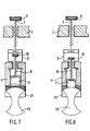
- Figure 7 and 8 schematic views of the tools in tensile test and compression test.
- FIGS. 1 and 2 show a test piece 15 in the form of a thin patch (for example from 3 to 5 mm) relative to the diameter (for example of the order of 25 mm), a patch in which symmetrically is produced to a diameter, two notches 16 in the shape of a half-moon of a relatively large diameter (for example 20 mm).
- a test piece 15 in the form of a thin patch (for example from 3 to 5 mm) relative to the diameter (for example of the order of 25 mm), a patch in which symmetrically is produced to a diameter, two notches 16 in the shape of a half-moon of a relatively large diameter (for example 20 mm).
- the specimen in question is or is not protected against oxidation and will have undergone a simulation of reentry into the atmosphere.
- Figure 3 shows a traction tool developed to provide this type of test. It consists of a male support jaw 1 which cooperates with a guide sleeve 2 by means of its inclined walls 12. A female jaw 3 is fixed inside the end of the jaw 1 by needle screws 13 This female jaw 3 of generally tubular shape has an internal machining with inclined faces 17 closing downwards which contains two jaws 4 also of corresponding profile bearing on the female jaw.
- a knurled nut 9 makes it possible to move a threaded rod 7 bearing on a plug 6 itself secured to an operating core 5.
- another knurled nut 10 can act on another threaded rod 8 whose lower end is in abutment against a clamping wedge 11 located inside the female jaw, between the jaws 4.
- the end profile of the clamping wedge is rounded to s 'apply exactly to the rounded edge of the test piece.
- the sleeve 2 contains at its lower part another identical male jaw 2.
- the jaws 4 of each jaw enclose the test piece 15 subjected to the tensile tests.
- Each jaw 4 is shown in more detail in FIGS. 4 and 5. It essentially consists of a vertical leg 19 surmounting a support plate 20, a leg of which an outer wall 18 is inclined at an angle ⁇ of approximately 10 ° relative to the vertical, corresponding to the inclination of the inclined faces 17 of the female jaw.
- the support plate 20 at the lower part of the jaw 4 is ridged which improves the tightening with the test piece.
- two shoulders 21 in an arc form an overhang with respect to said ridged plate.
- the arc of a circle has the same radius as that of the notches 16 in half-moons provided on the test piece 15.
- FIG. 6 is a simplified schematic representation of the tool shown in Figure 3.
- the female jaws 3 are shown schematically by inclined flanges provided on the male jaw 1 and on the sleeve 2.
- the same adjustable tool with the arcs of a circle at the ends of the test piece can be used for both tensile and compression tests, without initiating shear fractures, at the level of the contacts with the tools, cannot occur during tensile tests.
- the tests thus carried out provide additional information for the quantification of the residual tensile or compressive strength of a material after an atmospheric reentry.
Landscapes
- Engineering & Computer Science (AREA)
- Remote Sensing (AREA)
- Aviation & Aerospace Engineering (AREA)
- Physics & Mathematics (AREA)
- Health & Medical Sciences (AREA)
- Life Sciences & Earth Sciences (AREA)
- Chemical & Material Sciences (AREA)
- Analytical Chemistry (AREA)
- Biochemistry (AREA)
- General Health & Medical Sciences (AREA)
- General Physics & Mathematics (AREA)
- Immunology (AREA)
- Pathology (AREA)
- Investigating Strength Of Materials By Application Of Mechanical Stress (AREA)
- Sampling And Sample Adjustment (AREA)
Applications Claiming Priority (2)
| Application Number | Priority Date | Filing Date | Title |
|---|---|---|---|
| FR9011602A FR2667152B1 (fr) | 1990-09-20 | 1990-09-20 | Dispositif d'essai en traction et compression sur une eprouvette apres simulation de rentree en atmosphere. |
| FR9011602 | 1990-09-20 |
Publications (1)
| Publication Number | Publication Date |
|---|---|
| EP0477085A1 true EP0477085A1 (de) | 1992-03-25 |
Family
ID=9400482
Family Applications (1)
| Application Number | Title | Priority Date | Filing Date |
|---|---|---|---|
| EP91402463A Withdrawn EP0477085A1 (de) | 1990-09-20 | 1991-09-17 | Vorrichtung zur Ausführung von Zug- und Druck-Tests an Proben nach Atmosphärenwiedereintrittssimulation |
Country Status (3)
| Country | Link |
|---|---|
| US (1) | US5195379A (de) |
| EP (1) | EP0477085A1 (de) |
| FR (1) | FR2667152B1 (de) |
Cited By (4)
| Publication number | Priority date | Publication date | Assignee | Title |
|---|---|---|---|---|
| FR2704649A1 (fr) * | 1993-04-30 | 1994-11-04 | Centre Nat Rech Scient | Machine de traction in situ et éprouvette pour microscope électronique à balayage. |
| CN101776550B (zh) * | 2010-02-04 | 2011-04-27 | 西北工业大学 | 一种用于管材试样的拉伸试验夹具 |
| CN104439384A (zh) * | 2014-11-04 | 2015-03-25 | 苏州精创光学仪器有限公司 | 盲孔法测残余应力钻孔钻具 |
| CN109916709A (zh) * | 2019-03-27 | 2019-06-21 | 江苏神马电力股份有限公司 | 一种试验接头及试验工装 |
Families Citing this family (7)
| Publication number | Priority date | Publication date | Assignee | Title |
|---|---|---|---|---|
| FR2779230B1 (fr) * | 1998-05-28 | 2000-08-18 | Centre Nat Etd Spatiales | Outillage de montage sur une machine de test de traction de deux elements colles l'un a l'autre |
| CN104502192B (zh) * | 2014-12-02 | 2017-02-22 | 江苏武进不锈股份有限公司 | 管材条形试样拉伸装置 |
| CN106114920B (zh) * | 2016-06-21 | 2018-07-06 | 哈尔滨工业大学 | 一种具有负载大范围可调功能的微重力模拟张力控制机构 |
| CN106018101B (zh) * | 2016-07-17 | 2018-09-25 | 倪菊莲 | 一种医用透析纸抗压能力检测时专用张紧装置 |
| CN106124317B (zh) * | 2016-07-17 | 2018-11-06 | 王辉 | 一种可精确测试的医用透析纸抗压能力检测装置 |
| CN105954108B (zh) * | 2016-07-17 | 2018-09-04 | 倪菊莲 | 一种医用透析纸抗压性能多级测试设备 |
| CN115979803A (zh) * | 2022-12-02 | 2023-04-18 | 西安鑫垚陶瓷复合材料股份有限公司 | 复合材料螺栓受力与热作用后剩余强度的测试方法及装置 |
Citations (2)
| Publication number | Priority date | Publication date | Assignee | Title |
|---|---|---|---|---|
| US1496803A (en) * | 1921-05-31 | 1924-06-10 | Amsler Alfred | Gripping device for testing machines and the like |
| DE3420717A1 (de) * | 1984-06-02 | 1985-12-05 | Anton-Peter Dr.-Ing. 7000 Stuttgart Betschart | Probekoerper mit aufnahmewerkzeug fuer zug-, druck- und knickversuche |
Family Cites Families (2)
| Publication number | Priority date | Publication date | Assignee | Title |
|---|---|---|---|---|
| US1527409A (en) * | 1920-05-28 | 1925-02-24 | Gustav A Hassel | Apparatus for testing materials |
| US2537322A (en) * | 1947-03-13 | 1951-01-09 | W C Dillon & Company Inc | Tensile grip |
-
1990
- 1990-09-20 FR FR9011602A patent/FR2667152B1/fr not_active Expired - Fee Related
-
1991
- 1991-09-17 EP EP91402463A patent/EP0477085A1/de not_active Withdrawn
- 1991-09-18 US US07/762,763 patent/US5195379A/en not_active Expired - Fee Related
Patent Citations (2)
| Publication number | Priority date | Publication date | Assignee | Title |
|---|---|---|---|---|
| US1496803A (en) * | 1921-05-31 | 1924-06-10 | Amsler Alfred | Gripping device for testing machines and the like |
| DE3420717A1 (de) * | 1984-06-02 | 1985-12-05 | Anton-Peter Dr.-Ing. 7000 Stuttgart Betschart | Probekoerper mit aufnahmewerkzeug fuer zug-, druck- und knickversuche |
Non-Patent Citations (1)
| Title |
|---|
| INDUSTRIAL LABORATORY vol. 41, no. 11, Novembre 1975, NEW YORK page 1743; KATS: 'GRIP FOR TENSILE TESTING OF BRITTLE MATERIALS' * |
Cited By (7)
| Publication number | Priority date | Publication date | Assignee | Title |
|---|---|---|---|---|
| FR2704649A1 (fr) * | 1993-04-30 | 1994-11-04 | Centre Nat Rech Scient | Machine de traction in situ et éprouvette pour microscope électronique à balayage. |
| WO1994025846A3 (fr) * | 1993-04-30 | 1995-01-12 | Centre Nat Rech Scient | Machine de traction in situ et eprouvette pour microscope electronique a balayage |
| US5606168A (en) * | 1993-04-30 | 1997-02-25 | Centre National De La Recherche Scientifique | In situ tensile testing machine and sample for a scanning electron microscope |
| CN101776550B (zh) * | 2010-02-04 | 2011-04-27 | 西北工业大学 | 一种用于管材试样的拉伸试验夹具 |
| CN104439384A (zh) * | 2014-11-04 | 2015-03-25 | 苏州精创光学仪器有限公司 | 盲孔法测残余应力钻孔钻具 |
| CN109916709A (zh) * | 2019-03-27 | 2019-06-21 | 江苏神马电力股份有限公司 | 一种试验接头及试验工装 |
| CN109916709B (zh) * | 2019-03-27 | 2022-03-08 | 江苏神马电力股份有限公司 | 一种试验接头及试验工装 |
Also Published As
| Publication number | Publication date |
|---|---|
| FR2667152B1 (fr) | 1993-07-30 |
| US5195379A (en) | 1993-03-23 |
| FR2667152A1 (fr) | 1992-03-27 |
Similar Documents
| Publication | Publication Date | Title |
|---|---|---|
| EP0477085A1 (de) | Vorrichtung zur Ausführung von Zug- und Druck-Tests an Proben nach Atmosphärenwiedereintrittssimulation | |
| FR2828125A1 (fr) | Dispositif d'outil a expansion pour pince a emboiture | |
| FR2806018A3 (fr) | Outil coupant | |
| EP0878287A1 (de) | Aufweitungsvorrichtung zum Formen von Muffen an Kunststoff- oder Kunststoff/Aluminium-Rohrenden | |
| FR2596491A1 (fr) | Procede et dispositif de premontage et de montage definitif d'un raccordement a bague coupante | |
| EP0452216B1 (de) | Gerät zum Scherprüfung von Prüflingen | |
| FR2566479A1 (fr) | Boulon d'ancrage a manchon expansible | |
| FR2722881A1 (fr) | Dispositif de prehension pour la realisation d'essais de traction a haute temperature sur des eprouvettes plates en materiau fragile | |
| FR2752886A1 (fr) | Procede d'assemblage de deux toles l'une sur l'autre ; assemblage ainsi obtenu | |
| FR2580526A1 (fr) | Dispositif de filiere pour rouler par etirage en fer plat et obtenir un element tubulaire | |
| FR3008147A1 (fr) | Dispositif de serrage d'ecrou | |
| FR2500556A1 (fr) | Dispositif de butee de fin de course d'amortisseur et appareil telescopique analogue | |
| EP0620057B1 (de) | Zweiteilige Matrize zum Ausrüsten einer Einzieh- und/oder Crimppresse. | |
| WO2023156284A1 (fr) | Dispositif de test et procédé de mesure de propriétés tribologiques | |
| EP2789417B1 (de) | Bohrführung für Rohre mit verschiedenen Durchmessern | |
| CH631788A5 (fr) | Dispositif d'attache a elements. | |
| FR2784805A1 (fr) | Manchon et cosse de jonction electrique pour cable electrique de basse et moyenne tension | |
| FR2594268A1 (fr) | Pince d'ancrage pour cable cylindrique. | |
| FR3112179A1 (fr) | Dispositif de fixation | |
| FR3148264A1 (fr) | procédé de fixation d’une première structure à une deuxième structure au moyen de vis guidées. | |
| FR2557296A1 (fr) | Dispositif de controle de la resistance d'une liaison soudee | |
| FR3138679A1 (fr) | Dispositif de maintien d’un tube | |
| WO2015124849A1 (fr) | Poincon pour un outil de sertissage et outil de sertissage muni d'un tel poincon | |
| EP1612890A1 (de) | Verbindungsteil für ein elektrisches Kabel, insbesondere für Mittelspannung | |
| FR2461536A1 (fr) | Poincon de decoupage |
Legal Events
| Date | Code | Title | Description |
|---|---|---|---|
| PUAI | Public reference made under article 153(3) epc to a published international application that has entered the european phase |
Free format text: ORIGINAL CODE: 0009012 |
|
| AK | Designated contracting states |
Kind code of ref document: A1 Designated state(s): AT DE ES GB NL |
|
| RAP1 | Party data changed (applicant data changed or rights of an application transferred) |
Owner name: AEROSPATIALE SOCIETE NATIONALE INDUSTRIELLE |
|
| 17P | Request for examination filed |
Effective date: 19920818 |
|
| 17Q | First examination report despatched |
Effective date: 19930518 |
|
| STAA | Information on the status of an ep patent application or granted ep patent |
Free format text: STATUS: THE APPLICATION IS DEEMED TO BE WITHDRAWN |
|
| 18D | Application deemed to be withdrawn |
Effective date: 19941120 |