EP0476830B1 - Method of operating concatenated optical amplifiers - Google Patents
Method of operating concatenated optical amplifiers Download PDFInfo
- Publication number
- EP0476830B1 EP0476830B1 EP91307469A EP91307469A EP0476830B1 EP 0476830 B1 EP0476830 B1 EP 0476830B1 EP 91307469 A EP91307469 A EP 91307469A EP 91307469 A EP91307469 A EP 91307469A EP 0476830 B1 EP0476830 B1 EP 0476830B1
- Authority
- EP
- European Patent Office
- Prior art keywords
- optical
- amplifier
- signal
- power
- amplifiers
- Prior art date
- Legal status (The legal status is an assumption and is not a legal conclusion. Google has not performed a legal analysis and makes no representation as to the accuracy of the status listed.)
- Expired - Lifetime
Links
Images


Classifications
-
- H—ELECTRICITY
- H04—ELECTRIC COMMUNICATION TECHNIQUE
- H04B—TRANSMISSION
- H04B10/00—Transmission systems employing electromagnetic waves other than radio-waves, e.g. infrared, visible or ultraviolet light, or employing corpuscular radiation, e.g. quantum communication
- H04B10/29—Repeaters
- H04B10/291—Repeaters in which processing or amplification is carried out without conversion of the main signal from optical form
- H04B10/293—Signal power control
- H04B10/2933—Signal power control considering the whole optical path
- H04B10/2935—Signal power control considering the whole optical path with a cascade of amplifiers
-
- H—ELECTRICITY
- H04—ELECTRIC COMMUNICATION TECHNIQUE
- H04B—TRANSMISSION
- H04B10/00—Transmission systems employing electromagnetic waves other than radio-waves, e.g. infrared, visible or ultraviolet light, or employing corpuscular radiation, e.g. quantum communication
- H04B10/29—Repeaters
- H04B10/291—Repeaters in which processing or amplification is carried out without conversion of the main signal from optical form
- H04B10/2912—Repeaters in which processing or amplification is carried out without conversion of the main signal from optical form characterised by the medium used for amplification or processing
-
- H—ELECTRICITY
- H01—ELECTRIC ELEMENTS
- H01S—DEVICES USING THE PROCESS OF LIGHT AMPLIFICATION BY STIMULATED EMISSION OF RADIATION [LASER] TO AMPLIFY OR GENERATE LIGHT; DEVICES USING STIMULATED EMISSION OF ELECTROMAGNETIC RADIATION IN WAVE RANGES OTHER THAN OPTICAL
- H01S2301/00—Functional characteristics
- H01S2301/02—ASE (amplified spontaneous emission), noise; Reduction thereof
-
- H—ELECTRICITY
- H01—ELECTRIC ELEMENTS
- H01S—DEVICES USING THE PROCESS OF LIGHT AMPLIFICATION BY STIMULATED EMISSION OF RADIATION [LASER] TO AMPLIFY OR GENERATE LIGHT; DEVICES USING STIMULATED EMISSION OF ELECTROMAGNETIC RADIATION IN WAVE RANGES OTHER THAN OPTICAL
- H01S3/00—Lasers, i.e. devices using stimulated emission of electromagnetic radiation in the infrared, visible or ultraviolet wave range
- H01S3/05—Construction or shape of optical resonators; Accommodation of active medium therein; Shape of active medium
- H01S3/06—Construction or shape of active medium
- H01S3/063—Waveguide lasers, i.e. whereby the dimensions of the waveguide are of the order of the light wavelength
- H01S3/067—Fibre lasers
- H01S3/06754—Fibre amplifiers
Definitions
- This invention relates generally to optical amplifiers and more particularly to a method of operating concatenated erbium-doped fiber optical amplifiers to provide an improved mode of operation.
- Optical amplifiers may replace optoelectronic regenerators in some terrestrial and undersea long-haul transmission systems.
- the attraction is the potential of creating a "lightpipe" that is transparent to the bit rate and transmission format, and can convey wavelength-division multiplexed signals without the need for multiple repeaters.
- the difficulties associated with transmitting data long distances arise from chromatic dispersion, polarization dispersion, transmission fiber nonlinearities, optical amplifier nonlinearities and the accumulation of noise.
- Recent experiments have used semiconductor and erbium-doped fiber amplifiers as linear repeaters in lightwave transmission systems. The longest transmission distance reported was 2200km. Less certain is the behavior of systems which have very long transmission distances, such as transoceanic systems operating over 7500 km.
- gain saturation of the optical amplifiers at any stage is caused by the extraction of power from the amplifier by the ASE and amplification of the signal and of the ASE from previous stages.
- Three methods of operating transmission systems are classified as free-running, constant-total power, and constant-signal power. Differences in performance of the three systems arise from the propagation of signal power and the buildup of the ASE.
- a method for reducing the accumulation of amplified spontaneous emission noise in a system of concatenated amplifiers is needed.
- This invention relates to an amplified lightwave system having concatenated optical amplifiers which, when operated in their saturated mode, provide a high signal-to-noise ratio.
- Current literature on amplified lightwave systems relate only to ideal, unsaturated optical amplifiers having gains which are unaffected by the amplified signal (noise) power. The current literature is not aware of the importance of, and ignores the reduction in amplifier gain caused by saturation, the competition between signal power and ASE noise power, and the efficiency of converting pump power into signal power. Because of this incomplete understanding of the operation of optical amplifiers, it is not obvious that the method of operating systems having saturated amplifiers, as we disclose, will work.
- the concatenated optical amplifiers of a transmission system in their saturated state.
- Conditions under which the amplified lightwave system operates satisfactorily for a large number of optical amplifiers are determined and three methods of controlling the system are identified.
- Two methods of operation regulate the optical power, i.e. either the signal power or the total optical power (signal power plus ASE noise power).
- a third method of operation is unregulated, yields a low level of ASE noise system and is efficient in converting pump power into signal power.
- These lightwave systems may be comprised of either lumped or distributed optical amplifiers.
- Distributed optical amplifiers provide lower noise operation than lumped optical amplifiers to reduce the saturation cause by accumulated ASE noise and improve the signal-to-noise ratio.
- this invention it is now possible to have a lightwave system that can comprise a large number of amplifiers and still have a signal-to-noise ratio which is usable. For example, with an amplifier spacing of 100 km, an optical transmission system of 80 amplifiers can be used to span most transoceanic routes.
- Erbium-doped fiber amplifiers have several advantages for transmission systems, including low insertion loss, polarization-independent gain, low crosstalk and high saturated output power. Very low noise figures have also been achieved with amplifiers having high small-signal gain, making them well-suited for concatenated amplifier systems that are sensitive to noise accumulation.
- the static system performance is simulated using the rate-equations of the erbium-amplifier that self-consistently account for the saturated amplifier noise.
- a simple modification of the equations also permits modeling of distributed optical amplifiers, where the fiber of the entire transmission span is lightly doped with erbium and is pumped to compensate for the transmission losses. Improved noise performance is disclosed for this type of amplifier. Then, a model of the saturated amplifier is used to simulate several possible operating conditions for concatenated optical amplifiers. Thereafter, the bit-error-rate performance of these systems and the effects of optical filtering are observed.
- the erbium-doped fiber amplifier is modeled as a three-level system having population densities in the ground level (1), metastable level (2) and pump level (3).
- the superscript + designates pump and ASE copropagating with the signal, and - when they counterpropagate to the signal.
- the absorption (a) and emission (e) cross-sections of the pump (p) and signal (s) are ⁇ s,p;a,e,e2 .
- Other parameters are the fiber core area, A, the signal-to-core overlap, ⁇ s , and the pump-to-core overlap, ⁇ p .
- the convective equations describing the spatial development of the pump, signal and ASE in the fiber are:
- the second term in (5) is ASE power produced in the amplifier per unit length within the amplifier homogeneous bandwidth ⁇ for both polarization states.
- the loss terms, ⁇ s,p represent internal loss of the amplifier, which is relevant in the case of the distributed optical amplifier whose length is equal to the span length and ⁇ s,p are the usual signal and pump attenuation in the transmission fiber.
- Equations (7) and (8) are useful in that they give the minimum noise figure and the maximum gain of an erbium-doped optical amplifier having cross-section ratios calculated from the absorption and fluorescence spectra of the amplifier.
- G max and F min are the upper and lower bounds to those values computed numerically for an amplifier with the same 1, ⁇ p and ⁇ s , but operating where the signal and ASE are present and the amplifier does not have maximum inversion.
- FIGs. 1 and 2 are curves of maximum gain and minimum noise of an erbium-doped fiber amplifier with an Al 2 0 3 -Si0 2 core.
- the system shown in Figure 3, is generalized to include the variation in the gain and output signal power of each stage caused by the build-up of the ASE power, P tot / ase,i.
- the amplifiers are assumed to be the same, and the spontaneous emission noise factor, n sp , is obtained from equations (1)-(5).
- a rectangular shaped ASE optical spectrum after the optical filter is assumed in the noise calculation. Later, the effects of non-ideal filtering on the ASE spectrum and system gain will be discussed.
- gain saturation of the optical amplifiers at any stage is caused by the extraction of power from the amplifier by the ASE, and amplification of the signal and of the ASE from previous stages.
- P s,0 is the transmitter output power.
- Optical isolators at each amplifier prevent the backward propagation of ASE through the system.
- the transmitter power, P s,0 could be produced with a power optical amplifier placed in front of the transmitter, but it is assumed that the amplifier is strongly saturated and P + a,0 is negligible. Also, P s,0 could be the total power of a WDM signal if the wavelength spacing is not too large to cause significant differences in the net gain of each channel.
- the behavior of the fiber-amplifier, and consequently the concatenated amplifiers depends on L, ⁇ p , ⁇ s , and on the power and direction of the pump.
- P + / p0, P - / p > 0 the noise factor of amplifiers having counterpropagating pumps
- P + / p0, P - / p > 0 because of higher population inversion at the input.
- the amplifier saturation power increases with pump power, even though the highest gain is G max once the maximum inversion is achieved.
- the span attenuation was chosen as representing 25 dB loss in 100 km of fiber and a 5 dB margin for amplifier insertion loss.
- the bandwidth corresponds to a 1 nm filter for an amplifier homogeneous linewidth of 25 nm.
- the ASE grows nearly linearly, causing the output signal power of successive amplifiers to decrease.
- the signal is reduced to 5.7 mW, and the ASE power is 3.25 mW in a 1 nm bandwidth.
- Brillouin scattering and self-phase modulation in the transmission fiber could cause further signal degradation.
- Constant amplitude signal transmission may suppress degradation caused by these fiber nonlinearities, but the degradation caused by the growth of ASE and the loss of signal power is unchanged.
- One means of reducing the accumulated ASE is to decrease the amplifier spacing while maintaining the total amplifier gain in the system, G system , equal to the fiber and component losses.
- the ASE optical power at the receiver is proportional to N(G 1/N / system((-1), where N is the number of amplifiers in the system, each having gain G 1/N / system.
- the noise performance improves for large N and in the limit of distributed amplification where the transmission fiber is also the gain medium, the ASE power is proportional to ln(G system ).
- the input signal power is 100 ⁇ W but is not constant in the distributed amplifier, rather it grows at the two ends where the pump power is large and is attenuated in the middle portion of the amplifier.
- the fluctuation in the signal level can be reduced by decreasing the erbium concentration and increasing the pump power to achieve constant inversion in the amplifier.
- Raman gain is significant, and is easily incorporated into equations 3-5 by adding terms having pump-power-dependent gain coefficients.
- the distributed amplifier used in this example is the bidirectionally pumped amplifier of Figure 5 with the span length of 100 km.
- the principal advantage of the distributed amplifier, low ASE, is clearly observed by comparing FIG. 5 with the lumped amplifier results of Figure 3, where the ASE power is two orders of magnitude higher.
- One disadvantage of the distributed amplifier is that the pump power requirements are approximately doubled because both the relatively high-power pump and the signal experience loss in the transmission fiber.
- nonlinearity of the transmission fiber may be more important in this embodiment rather than in the embodiment using lumped amplifiers. This could be advantageous for soliton transmission which relies upon self-phase modulation to sustain the soliton, however, it could cause pulse broadening for conventional optical pulse transmission.
- concatenated lumped amplifiers configured to operate in their saturation mode can be configured in several ways to provide a desired system performance.
- G o the unsaturated gain
- P in the total power at the input to the erbium-doped fiber.
- the unsaturated gain and saturation powers are determined from the fiber design and pump powers.
- the fiber amplifier is operated where the small-signal gain varies slowly with pump power, and the saturation power can be regulated by changing the pump power.
- G o,i G o (a constant)
- P sat,i is a parameter that can be adjusted in order to obtain system goals.
- An embodiment of system supervision has constant signal power at the output of each amplifier. Although this is not the most efficient mode of operating the system to convert the maximum amount of pump power to signal, it still is likely the preferred method of operation.
- the saturation power of each successive amplifier is increased slightly to compensate for the gain saturation caused by the build-up of the ASE.
- Figure 9 illustrates a case where P out,i , P ase,i and P sat,i are all increasing down the chain of amplifiers.
- the noise performance is similar to the free-running system when a smaller transmitter power is used but the average saturation power of the amplifiers is higher.
- constant signal power monitoring avoids blind operation of a system and enables adequate supervision of the signal's progress at each amplifier stage.
- Constant power monitoring may reduce the hardware complexity as the signal does not have to be independently sensed.
- detection at the receiver converts the light into an electrical signal, which for digital data transmission, is a string of "0"s and "1"s corrupted by electrical noise.
- the electrical noise is the sum of that produced by the receiver electronics, shot noise from the signal and ASE, signal-spontaneous (s-sp) beat noise and spontaneous-spontaneous (sp-sp) beat noise.
- the dominant noise is the s-sp beat noise, and where the optical filter bandwidth is considerably larger than the signal bandwidth, significant sp-sp beat noise is present too.
- the beat noise degradation can be estimated from the received signal and ASE optical powers.
- the beat noise degradation can be estimated from the received signal and ASE optical powers.
- I 2 s-sp 2I ase I 1 B e /B o
- I 2 sp-sp I 2 ase B e /B o
- I 1 2e ⁇ P s ⁇ s /hc
- ⁇ is the detection quantum efficiency.
- the electrical bandwidth is approximately one-half the data rate and the optical signal power in the 0's is assumed to be zero. Referring to Bell Sys. Tech. Jour., Vol. 52, No. 1, pp. 117-133 (1973) "Applications of Quantum Amplifiers in Simple Digital Optical Communication Systems" by S.D.
- the Q parameter at the receiver which is related to the achievable bit-error rate (BER) at the receiver is given by: where I 2 / noise "1” and I 2 / noise "0" on the total noise powers in a “1” and “0", respectively.
- B 1 is the single filter 3-dB bandwidth.
- the equivalent optical filter of the concatenated system after N stages has a shape f( ⁇ ) N , causing the system bandwidth to shrink as compared to a single filter.
- the propagation of signal and noise in concatenated optical amplifiers is dependent on properties of the amplifier and on the system design.
- the erbium-doped fiber amplifier is a good candidate for long-distance transmission because of its very low noise and high gain.
- a rate equation model of the fiber amplifier was used in the simulation of a transmission system. In a 1.5- ⁇ m transmission system, system reach beyond 10,000 km for 2.5 Gb/s (Sonet rate) seems possible, discounting the effects of dispersion and transmission fiber nonlinearities. Additional distance can be gained by increasing the launched signal power, by using low-loss transmission fiber, by minimizing the amplifier insertion loss, and/or by reducing the optical filter bandwidth.
- Distributed fiber-amplifiers may achieve extremely low-noise operation, at some expense in requiring high pump power and potentially shorter span lengths.
- the erbium-doped distributed amplifier is similar to Raman amplification in transmission fibers.
- Standard optical filter designs appear to be compatible with typical system requirements. Roughly a factor of 2 reduction in system bandwidth compared to the single filter bandwidth should be possible after 100 amplifier stages. Furthermore, some correction to structure in the amplifier gain spectrum may be done by appropriating tailoring the optical filter transmission characteristics.
Landscapes
- Physics & Mathematics (AREA)
- Electromagnetism (AREA)
- Engineering & Computer Science (AREA)
- Computer Networks & Wireless Communication (AREA)
- Signal Processing (AREA)
- Lasers (AREA)
- Optical Communication System (AREA)
Description
- This invention relates generally to optical amplifiers and more particularly to a method of operating concatenated erbium-doped fiber optical amplifiers to provide an improved mode of operation.
- Optical amplifiers may replace optoelectronic regenerators in some terrestrial and undersea long-haul transmission systems. The attraction is the potential of creating a "lightpipe" that is transparent to the bit rate and transmission format, and can convey wavelength-division multiplexed signals without the need for multiple repeaters. The difficulties associated with transmitting data long distances arise from chromatic dispersion, polarization dispersion, transmission fiber nonlinearities, optical amplifier nonlinearities and the accumulation of noise. Recent experiments have used semiconductor and erbium-doped fiber amplifiers as linear repeaters in lightwave transmission systems. The longest transmission distance reported was 2200km. Less certain is the behavior of systems which have very long transmission distances, such as transoceanic systems operating over 7500 km.
- The evolution of the signal and noise in concatenated optical amplifiers has been discussed in Quantum Electron, Vol. QE-18, No. 10 pp. 1560-1568 (1982) "S/N and Error Rate Performance in AlGaAs Semiconductor Laser Preamplifier and Linear Repeater Systems" by T. Mukai et al.; for linear optical amplifiers. However, in practice, amplifier saturation must be considered in view of the competition between the amplified spontaneous emission (ASE) and the signal for the power available from the optical amplifiers. With multiple amplifiers, this problem becomes especially severe as the ASE, which is characterized as noise, builds up in successive amplifiers to quickly cause a noise power that is higher than that of a single amplifier. In a transmission system having concatenated optical amplifiers, gain saturation of the optical amplifiers at any stage is caused by the extraction of power from the amplifier by the ASE and amplification of the signal and of the ASE from previous stages. Three methods of operating transmission systems are classified as free-running, constant-total power, and constant-signal power. Differences in performance of the three systems arise from the propagation of signal power and the buildup of the ASE.
- A method for reducing the accumulation of amplified spontaneous emission noise in a system of concatenated amplifiers is needed.
- It is now disclosed that the buildup of ASE noise in a system of either lumped or distributed concatenated optical amplifiers can be limited by operating at least a plurality of the optical amplifiers to provide unsaturated gain which is greater than the loss of the system and where the various optical amplifiers are operated in their saturated state.
-
- FIGs. 1 and 2 are curves of maximum gain (Gmax) and minimum noise (Fmin) of an Er3+ fiber amplifier with Al2O3-SiO2 core, 1=9 at λso = 1531nm; a pump wavelength of 1450nm < λp < 1510nm and a signal wavelength of 1500nm < λs < 1600 nm;
- FIG. 3 is a schematic of a concatenated amplifier system wherein amplifier gain is Gi, saturation power is Psat, the total loss in a transmission span is L, and the optical filter bandwidth is Bo;
- FIG. 4 is a plot of signal power (Ps) and amplified spontaneous emission power (Pase) of concatenated lumped optical amplifiers for copropagating (―) and counterpropagating (---) pump signals where pump power is 30mW, Pso=9mW, b-0.04 and L=0.001;
- FIG. 5 is a plot of signal power (Ps) and amplified spontaneous emission power (Pase) in a bidirectionally-pumped distributed fiber amplifier where P+ p = P- p = 30mW, Lamp = 100km, NEr3+ = 8.3 x 1014cm-3, Ps,0 = 0.1mW and b=0.04; the arrows identify the associated scale;
- FIG. 6 is a plot of signal power (Ps) and amplified spontaneous emission power (Pase) in concatenated distributed fiber amplifiers of the type illustrated in FIG. 4;
- FIG. 7 is a plot of total power (PTOT), signal power (Ps), gain (G) and amplified spontaneous emission power (Pase) of a free-running concatenation of lumped amplifiers where Go = 35dB, Psat = 8mW, LGo=3,Pso=1mW, and Nsp = 1.3; the arrows identify the associated scale;
- FIG. 8 is a plot of total power (PTOT), signal power (Ps) and amplified spontaneous emission power (Pase) of concatenated lumped optical amplifiers with constant total output power where Go=35db, Psat = 8mW, LG0 = 3, Ps,0 = 8.9mW, and Nsp = 1.3;
- FIG. 9 is a plot of saturated power (Psat), signal power (Ps) and amplified spontaneous emission power (Pase) of concatenated lumped optical amplifiers with constant signal power where Go = 35dB, LGo = 3, Ps,0 = 5mW and Nsp = 1.3;
- FIGs. 10 and 11 are plots of the evolution of ASE spectrum through a transmission system with 1nm bandpass optical filters at each stage, FIG. 10 being of flat gain and ASE spectrum within the filter bandwidth and FIG. 11 being with amplifier gain and ASE decreased 5% within the 1nm filter bandwidth.
-
- This invention relates to an amplified lightwave system having concatenated optical amplifiers which, when operated in their saturated mode, provide a high signal-to-noise ratio. Current literature on amplified lightwave systems relate only to ideal, unsaturated optical amplifiers having gains which are unaffected by the amplified signal (noise) power. The current literature is not aware of the importance of, and ignores the reduction in amplifier gain caused by saturation, the competition between signal power and ASE noise power, and the efficiency of converting pump power into signal power. Because of this incomplete understanding of the operation of optical amplifiers, it is not obvious that the method of operating systems having saturated amplifiers, as we disclose, will work.
- In this invention we disclose a method of operating an amplified lightwave system which has a relatively high signal to noise ratio. More specifically, in this invention, relatively high signal-to-noise ratio is obtained by operating the concatenated optical amplifiers of a transmission system in their saturated state. Conditions under which the amplified lightwave system operates satisfactorily for a large number of optical amplifiers (e.g. greater than 10) are determined and three methods of controlling the system are identified. Two methods of operation regulate the optical power, i.e. either the signal power or the total optical power (signal power plus ASE noise power). A third method of operation is unregulated, yields a low level of ASE noise system and is efficient in converting pump power into signal power. These lightwave systems may be comprised of either lumped or distributed optical amplifiers. Distributed optical amplifiers provide lower noise operation than lumped optical amplifiers to reduce the saturation cause by accumulated ASE noise and improve the signal-to-noise ratio. With this invention, it is now possible to have a lightwave system that can comprise a large number of amplifiers and still have a signal-to-noise ratio which is usable. For example, with an amplifier spacing of 100 km, an optical transmission system of 80 amplifiers can be used to span most transoceanic routes.
- Erbium-doped fiber amplifiers have several advantages for transmission systems, including low insertion loss, polarization-independent gain, low crosstalk and high saturated output power. Very low noise figures have also been achieved with amplifiers having high small-signal gain, making them well-suited for concatenated amplifier systems that are sensitive to noise accumulation. Below, the static system performance is simulated using the rate-equations of the erbium-amplifier that self-consistently account for the saturated amplifier noise. A simple modification of the equations also permits modeling of distributed optical amplifiers, where the fiber of the entire transmission span is lightly doped with erbium and is pumped to compensate for the transmission losses. Improved noise performance is disclosed for this type of amplifier. Then, a model of the saturated amplifier is used to simulate several possible operating conditions for concatenated optical amplifiers. Thereafter, the bit-error-rate performance of these systems and the effects of optical filtering are observed.
- The erbium-doped fiber amplifier is modeled as a three-level system having population densities in the ground level (1), metastable level (2) and pump level (3). The rate equations describing the effects of the pump (Pp), signal (Ps) and ASE (Pa) power on these populations are:
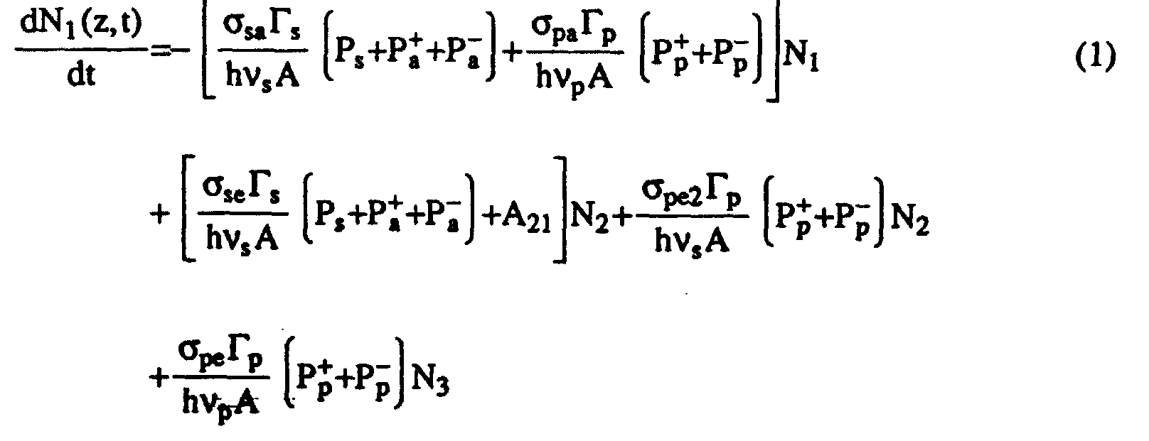 and by conservation, N3=Nt-N1-N2, where N1, N2 and N3 are the populations densities of the ground level, metastable level and pump level respectively and Nt is the total Er3+ density. The superscript + designates pump and ASE copropagating with the signal, and - when they counterpropagate to the signal. The absorption (a) and emission (e) cross-sections of the pump (p) and signal (s) are σs,p;a,e,e2. With pumping into the metastable level with (λp= 1450-1500nm), the amplifier behaves as a two level system with the pump emission cross-section σpe2=σpe; pumping into other absorption bands (eg. λp=980mn) have σpe2=0. Other parameters are the fiber core area, A, the signal-to-core overlap, Γs, and the pump-to-core overlap, Γp. No other effects of the radial distribution of ions or the optical mode are included here, since it is assume that the erbium ions are confined to the region of the optical mode's peak intensity and Γs,p are small. The nonradiative transition rate from level 3 to 2 is A32 and the radiative transition rate from level 2 to 1 is A21. In calculating the behavior of concatenated fiber amplifiers, the parameters for erbium in alumino-silicate glass, pumped at λp=1480nm, and amplifying a signal at λs=1545nm were used. Table 1 summarizes the material parameters and typical fiber parameters applicable to fiber amplifiers.
Fiber-Amplifier Parameters Used in Calculations λp = 1480 nm Δν = 3100 GHz (25 nm) λs = 1545 nm A21 = 100 s-1 σpe = σpe2 = 0.42×10⁻²¹ cm2 A32 = 109s-1 σpa = 1.86×10⁻²¹ cm2 A = 12.6×10⁻⁸ cm2 σse = 5.03×10 21 cm2 Γs = Γp = 0.4 σsa = 2.85×10⁻²¹ cm2 - The convective equations describing the spatial development of the pump, signal and ASE in the fiber are:

 The second term in (5) is ASE power produced in the amplifier per unit length within the amplifier homogeneous bandwidth Δν for both polarization states. The loss terms, αs,p represent internal loss of the amplifier, which is relevant in the case of the distributed optical amplifier whose length is equal to the span length and αs,p are the usual signal and pump attenuation in the transmission fiber.
- Equations (1)-(5) are solved for steady-state conditions where dNi/dt = 0, to yield the output ASE power and the amplified signal with amplifier saturation. The amplifier gain is calculated as G = Ps(1)/Ps(0) and the spontaneous emission noise factors in the forward and backward directions are defined as n + / sp = P + / a(1)/(2HνsΔν(G-1))and n - / sp = P - / a(0)/(2hνsΔν(G-1)). The evolution of the signal and noise in the transmission system is computed numerically. However, simplifications to these equations yield convenient expressions for the achievable gain and amplifier noise figure, F = 2nsp. In the case of pumping into the metastable level (σpe2 = σpe), and in the limits where Ps = 0, and
(P + / p+P - / p)>>Pth = hνpAA21 /σpa,Γp, it is derived from equations (1) and (2) that Equations (7) and (8) are useful in that they give the minimum noise figure and the maximum gain of an erbium-doped optical amplifier having cross-section ratios calculated from the absorption and fluorescence spectra of the amplifier. These values of Gmax and Fmin are the upper and lower bounds to those values computed numerically for an amplifier with the same 1, λp and λs, but operating where the signal and ASE are present and the amplifier does not have maximum inversion. Figures 1 and 2 show the calculated Gmax and Fmin for an alumino-silicate glass host with λp ranging from 1450 nm to 1510 nm, and lso = 9 for λs0 = 1531 nm. See IEEE J. Lightwave Tech. Vol. 7, No. 5, pp. 835-845 (1989), "Amplification of Spontaneous Emission in Erbium-doped Single-mode Fibers" by E. Desurvire et al. Pumping at short wavelengths enables high amplifier inversion resulting in high gain and a low noise figure. Quantum-limited signal amplification, i.e., F = 3 dB, is practically achieved by pumping at λp = 1450 nm. In a recent experiment, a noise figure F = 4.1 dB was reported with 1493 nm pumping which agrees closely to Fmin = 4.3 dB predicted for the alumino-silicate glass host.
- In a transmission system, the optical amplifiers are concatenated with the transmission fiber, and optical filters are inserted to reject the ASE outside of the signal band. FIGs. 1 and 2 are curves of maximum gain and minimum noise of an erbium-doped fiber amplifier with an Al203-Si02 core. The system, shown in Figure 3, is generalized to include the variation in the gain and output signal power of each stage caused by the build-up of the ASE power, P tot / ase,i. In the case of the fiber-amplifier, which will be discussed first, the amplifiers are assumed to be the same, and the spontaneous emission noise factor, nsp, is obtained from equations (1)-(5). The loss of each span, L, and the normalized filter bandwidth b = B0/Δν, are kept constant. The optical filter bandwidth, Bo = 1 nm (126 GHz) is a compromise between minimizing the ASE power outside the signal bandwidth, and ensuring that the bandwidth of the cascaded amplifiers remains large enough for Gb/s signals. A rectangular shaped ASE optical spectrum after the optical filter is assumed in the noise calculation. Later, the effects of non-ideal filtering on the ASE spectrum and system gain will be discussed.
- In a system of concatenated lumped fiber amplifiers, gain saturation of the optical amplifiers at any stage is caused by the extraction of power from the amplifier by the ASE, and amplification of the signal and of the ASE from previous stages. At the ith amplifier then the total output powers of the ASE and signal are:
- The behavior of the fiber-amplifier, and consequently the concatenated amplifiers, depends on L, λp, λs, and on the power and direction of the pump. For example, the noise factor of amplifiers having co-propagating pump (P + / p+ > 0, P - / p=0) is typically lower than those having counterpropagating pumps (P + / p0, P - / p > 0) because of higher population inversion at the input. Also, the amplifier saturation power increases with pump power, even though the highest gain is Gmax once the maximum inversion is achieved.
- Figure 4 shows the output signal power and the total output ASE power of a concatenated amplifier system for both copropagating and counterpropagating pump and for typical amplifier conditions, L = 30 dB span attenuation and a normalized bandwidth of b = 0.04. The span attenuation was chosen as representing 25 dB loss in 100 km of fiber and a 5 dB margin for amplifier insertion loss. The bandwidth corresponds to a 1 nm filter for an amplifier homogeneous linewidth of 25 nm. With a transmitter signal power, Pso = 9 mW, the saturated gain of every optical amplifier is 30 dB, which is 5 dB lower than Go = 35 dB. The long transient response time of gain saturation in erbium-doped fiber-amplifiers enables them to operate saturated in Gb/s systems without causing patterning or crosstalk penalties. See Opt. Lett., Vol. 14, No. 16, pp. 880-882 (1989) 'Transient Gain and Crosstalk in Erbium-doped Fiber Amplifiers" by C.R. Giles, et al. Additionally, in these highly saturated amplifiers good conversion efficiency of the pump power into signal power is achieved; of the 30 mW pump in this example, 30% is converted to amplified signal.
- In the transmission system, the ASE grows nearly linearly, causing the output signal power of successive amplifiers to decrease. After 10,000 km, with copropagating-pump amplifiers, the signal is reduced to 5.7 mW, and the ASE power is 3.25 mW in a 1 nm bandwidth. With the counterpropagating pump, the amplifier noise figure is slightly higher, resulting in P tot / ase = 3.65 mW at the output of the final amplifier. At the high powers in these optically amplified systems, Brillouin scattering and self-phase modulation in the transmission fiber could cause further signal degradation. Constant amplitude signal transmission (frequency-shift keying or phase-shift keying), or soliton transmission, may suppress degradation caused by these fiber nonlinearities, but the degradation caused by the growth of ASE and the loss of signal power is unchanged. One means of reducing the accumulated ASE is to decrease the amplifier spacing while maintaining the total amplifier gain in the system, Gsystem, equal to the fiber and component losses. Then the ASE optical power at the receiver is proportional to N(G 1/N / system((-1), where N is the number of amplifiers in the system, each having gain G 1/N / system. The noise performance improves for large N and in the limit of distributed amplification where the transmission fiber is also the gain medium, the ASE power is proportional to ln(Gsystem).
- We refer now to a system having concatenated distributed fiber amplifiers. Distributed amplifiers are known to have the potential of attaining very low noise figures because the signal level is kept relatively high throughout the amplifier. For the erbium amplifier, where the characteristic length is 1/ΓsσseNt, the dopant density can be reduced to yield very long amplifiers that are themselves the transmission fiber. The amplifier length can also be increased by confining the erbium to a small core diameter to reduce the overlap between the signal and the doped region. Loss in the fiber from Rayleigh scattering, OH absorption, impurities, and the like, limit the maximum length that can be used in a distributed amplifier, and is incorporated in the model with the loss terms αs and αp in equations 3-5. Figure 5 illustrates a 100-km long distributed amplifier, with a normal attenuation loss of 0.25 dB/km (as = αp = 5.76×10⁻⁵ m-1) and bidirectionally pumped with P + / p = P - / p = 30 mW. To achieve unity gain, the fiber is doped with Nt = 8.3×1014 cm-3, which is approximately a thousand times less than in a conventional lumped amplifier. The input signal power is 100 µW but is not constant in the distributed amplifier, rather it grows at the two ends where the pump power is large and is attenuated in the middle portion of the amplifier. If required by other constraints of the system, the fluctuation in the signal level can be reduced by decreasing the erbium concentration and increasing the pump power to achieve constant inversion in the amplifier. At these higher pump powers (Pp>50 mW), Raman gain is significant, and is easily incorporated into equations 3-5 by adding terms having pump-power-dependent gain coefficients.
- Figure 6 illustrates the propagation of the ASE and signal through a series of concatenated distributed amplifiers where the output signal power from each span is kept constant at Ps,0 = 0.1 mW and there is no coupling loss between amplifiers. The distributed amplifier used in this example is the bidirectionally pumped amplifier of Figure 5 with the span length of 100 km. The principal advantage of the distributed amplifier, low ASE, is clearly observed by comparing FIG. 5 with the lumped amplifier results of Figure 3, where the ASE power is two orders of magnitude higher. One disadvantage of the distributed amplifier is that the pump power requirements are approximately doubled because both the relatively high-power pump and the signal experience loss in the transmission fiber. Also, since the signal power is relatively high throughout the system, nonlinearity of the transmission fiber may be more important in this embodiment rather than in the embodiment using lumped amplifiers. This could be advantageous for soliton transmission which relies upon self-phase modulation to sustain the soliton, however, it could cause pulse broadening for conventional optical pulse transmission.
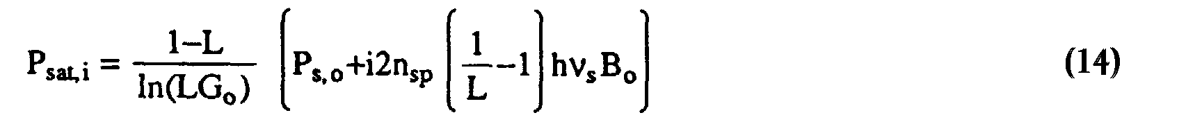
- In accordance with the principles of the invention, concatenated lumped amplifiers configured to operate in their saturation mode can be configured in several ways to provide a desired system performance. Beginning with the assumptions of local homogeneous saturation of the gain coefficient g, i.e., g = (1/(1+P/Psat)), and uniform pumping of the amplifier, an implicit form of the amplifier gain is:where Go is the unsaturated gain and Pin is the total power at the input to the erbium-doped fiber. See A.E. Siegman, "Lasers", University Service Books (Mill Valley, Ca.) 1986. With this definition of Psat, Pout = 0.69 Psat when G = Go/2, Go >> 1. Self-saturation from the ASE produced within an amplifier is not included, but the ASE is propagated through the concatenated spans and causes saturation of following amplifiers. The total power and the signal power at the output of the doped fiber of the ith amplifier is then:

- An embodiment of system supervision has constant signal power at the output of each amplifier. Although this is not the most efficient mode of operating the system to convert the maximum amount of pump power to signal, it still is likely the preferred method of operation. Now Ps,i = Ps,0, consequently LGi = 1 andThe saturation power of each successive amplifier is increased slightly to compensate for the gain saturation caused by the build-up of the ASE. Figure 9 illustrates a case where Pout,i, Pase,i and Psat,i are all increasing down the chain of amplifiers. Here, Psat,1 and at the final amplifier stage Psat,100 = 7.8 mW. = 4.6 mW. The noise performance is similar to the free-running system when a smaller transmitter power is used but the average saturation power of the amplifiers is higher. Upon comparing the three methods of operation, it appears that issues of system operation, supervision and maintenance, rather than noise, will dictate which method would be preferred for a system. For example, constant signal power monitoring avoids blind operation of a system and enables adequate supervision of the signal's progress at each amplifier stage. Constant power monitoring, however, may reduce the hardware complexity as the signal does not have to be independently sensed.
- Once signal and noise have propagated through all the amplifiers, detection at the receiver converts the light into an electrical signal, which for digital data transmission, is a string of "0"s and "1"s corrupted by electrical noise. The electrical noise is the sum of that produced by the receiver electronics, shot noise from the signal and ASE, signal-spontaneous (s-sp) beat noise and spontaneous-spontaneous (sp-sp) beat noise. In quantum-limited detection, the dominant noise is the s-sp beat noise, and where the optical filter bandwidth is considerably larger than the signal bandwidth, significant sp-sp beat noise is present too.
- The beat noise degradation can be estimated from the received signal and ASE optical powers. For this purpose, (See IEEE J. Quantum Electron, Vol. QE-16, No. 10, pp. 1073-1081 (1980), "Noise and Error Rate Performance of Semiconductor Laser Amplifiers in PCM-IM Optical Transmission Systems" by Y. Yamamoto; and SPIE Conf. on Fiber Lasers and Amplifiers, Boston, Mass. Paper 1171-32 (1989) "Erbium-doped Fiber Amplifiers for High Speed Fiber-Optic Communication Systems" by C.R. Giles, et al.), it is necessary to know the electrical noise power produced by the beat terms expressed in terms of the signal and ASE photocurrents.where I 2 / noise "1" and I 2 / noise "0" on the total noise powers in a "1" and "0", respectively. For the gaussian noise approximation, Q = 7.65 when the BER = 1×10-14. From equations 17 and 18, and assuming that other noise effects are small, Q can be expressed in terms of RB = Bo/Be and Rase = Pase /Ps :
 Most often RB is specified and Rase is calculated to determine the maximum ASE power that can be tolerated to achieve the desired BER. For example, with 1 nm wide optical filters (Bo=126 GHz at 1545 nm) and Be = 1.25 GHz (2.5 Gb/s data rate), then for Q = 7.65, Rase = 0.74; the ASE power is approximately 75% of the signal power to achieve a BER floor of 1×10-14. Slight improvement in the system sensitivity can be achieved by using a narrower bandwidth optical filter at the receiver to reduce the sp-sp beat noise.
- All of the previous examples satisfied the criterion of the BER floor <10-14 for a transmission distance of 10,00 km. This performance amply exceeds typical transoceanic requirements of 7500 km, although a large margin may be required as additional impairments may occur, including higher amplifier noise figure, device aging and higher fiber loss. The distributed amplifier example had the best noise performance with Rase = 0.449 at 10,000 km even though the input and output signal power of each stage was only 100 µW. The values of Rase for the previous examples of free-running, regulated Pout, and regulated Ps were 0.74, 0.60 and 0.71 respectively; the low value for constant Pout resulted from having a slightly higher transmitter power. In soliton transmission systems where the average signal power is several milliwatts, even better signal-to-noise ratios would be achievable in distributed amplifiers. In lumped amplifier systems, the example of constant total power operation gave only slightly better performance than the free-running and constant signal power systems.
- The ASE power calculations of the earlier sections were made on the premise that each amplifier had an ideal rectangular bandpass filter and that the amplifier gain spectrum was flat. In practice the filter is not ideal and the gain spectrum in the filter passband is not flat. Thus, the approximate ASE spectral shape at the end of the concatenated amplifiers is determined. First, the ASE spectrum and the gain is assumed to vary linearly within the filter passband, i.e., Pase Gi ∝ 1 + a(λ-λc) where a is a measure of the ASE flatness and λc, is the filter center wavelength. Also, identical filters are used at each amplifier, although this would not be true in practice and some averaging of the filter function would occur. In the filter model, a three-stage, double half-wave interference filter is used whose transmission function is f(λ) = 1/[1+((λ-λc)/B1)6] where B1 is the single filter 3-dB bandwidth. This is a standard filter type that can be made with low insertion loss and is a close approximation to the desired rectangular filter. The equivalent optical filter of the concatenated system after N stages has a shape f(λ)N, causing the system bandwidth to shrink as compared to a single filter. With this filter function, the 3-dB bandwidth after N stages is reduced by (ln2/N)1/6 for large N; in the case of N = 100, the system bandwidth is 43.7% less than that of a single filter. Normally, the system optical bandwidth is specified and in the examples of this paper then the single filter bandwidth B1 = 2.29Bo = 2.29 nm.
- Once the filter characteristics are known, the ASE power after N stages is calculated as:In the limiting case of special interest, where the signal power at each amplifier stage is constant, the problem is simplified as LGi(λ) = 1. Additionally, if it is assumed that a = 0 then the spectrum of the ASE after N stages, S(λ), is simply:
 Figure 10 shows the ASE spectrum for 1 to 100 amplifier stages. The ASE spectrum evolves to be very similar in shape to the system transfer function because most of the ASE originates from stages with N >> 1, where the system transfer function is only slowly varying. After 30 stages, the ASE spectrum is one-half the width of the spectrum from a single amplifier + filter. Correcting for this in the noise calculations of equations (1)-(5) could be approximated by having Bo being the accumulated ASE bandwidth, not the bandwidth of a single filter.
- Finally, if the amplifier gain spectrum is not flat through the filter passband, additional distortion of the accumulated gain and ASE spectrum results. Figure 11 shows the accumulated ASE spectrum where a = -0.05, i.e., each amplifier gain decreases by 5% over the filter bandwidth (1 nm). This causes the ASE spectrum to evolve to shorter wavelengths, and become considerably narrower and less flat-topped. After 100 amplifiers, the 3 dB bandwidth of the system is 0. 156 of the single-filter bandwidth. The effect of the distortion would be minimized by centering the signal at the peak of the ASE spectrum. Also, this distortion may be corrected by distorting the filter shape slightly to compensate the gain spectrum and improve the net gain flatness over the filter passband.
- The propagation of signal and noise in concatenated optical amplifiers is dependent on properties of the amplifier and on the system design. The erbium-doped fiber amplifier is a good candidate for long-distance transmission because of its very low noise and high gain. A rate equation model of the fiber amplifier was used in the simulation of a transmission system. In a 1.5-µm transmission system, system reach beyond 10,000 km for 2.5 Gb/s (Sonet rate) seems possible, discounting the effects of dispersion and transmission fiber nonlinearities. Additional distance can be gained by increasing the launched signal power, by using low-loss transmission fiber, by minimizing the amplifier insertion loss, and/or by reducing the optical filter bandwidth.
- Distributed fiber-amplifiers may achieve extremely low-noise operation, at some expense in requiring high pump power and potentially shorter span lengths. In this respect, the erbium-doped distributed amplifier is similar to Raman amplification in transmission fibers.
- Standard optical filter designs appear to be compatible with typical system requirements. Roughly a factor of 2 reduction in system bandwidth compared to the single filter bandwidth should be possible after 100 amplifier stages. Furthermore, some correction to structure in the amplifier gain spectrum may be done by appropriating tailoring the optical filter transmission characteristics.
Claims (8)
- A method of operating an optical communication system having a transmitter for generating an optical radiation signal, a receiver of said signal, and an optical fiber communication link interposed between said transmitter and said receiver and having transmission optical fibers concatenated with optical amplifiers (OA) for amplifying an optical signal as it advances from one amplifier to the next from the transmitter to the receiver, comprising the steps of:operating each optical amplifier in its saturated state, andamplifying the optical signal as it advances through the optical fiber communication link from one optical amplifier to the next to a power level at the output of each optical amplifier which is substantially constant regardless of the power level of the optical signal received at the input of that optical amplifier.
- The method of claim 1 wherein said concatenated optical amplifiers comprise distributed optical amplifiers.
- The method of claim 1 wherein said concatenated optical amplifiers comprise lumped optical amplifiers.
- The method of claim 1 wherein said concatenated optical amplifiers comprise erbium doped fiber optical amplifiers.
- The method of claim 1 wherein said concatenated optical amplifiers are spaced greater than seventy kilometers apart.
- The method of claim 1 wherein the saturated gain of each optical amplifier is set to provide substantially constant signal power at the output of each optical amplifier.
- The method of claim 1 wherein the pump saturation power of each successive optical amplifier is increased to compensate for the gain saturation caused by the increase of amplified spontaneous emission noise.
- The method of claim 1 wherein the pump saturation power of each optical amplifier is substantially constant.
Applications Claiming Priority (2)
| Application Number | Priority Date | Filing Date | Title |
|---|---|---|---|
| US571958 | 1990-08-23 | ||
| US07/571,958 US5117303A (en) | 1990-08-23 | 1990-08-23 | Method of operating concatenated optical amplifiers |
Publications (3)
| Publication Number | Publication Date |
|---|---|
| EP0476830A2 EP0476830A2 (en) | 1992-03-25 |
| EP0476830A3 EP0476830A3 (en) | 1992-07-08 |
| EP0476830B1 true EP0476830B1 (en) | 1999-05-06 |
Family
ID=24285763
Family Applications (1)
| Application Number | Title | Priority Date | Filing Date |
|---|---|---|---|
| EP91307469A Expired - Lifetime EP0476830B1 (en) | 1990-08-23 | 1991-08-13 | Method of operating concatenated optical amplifiers |
Country Status (4)
| Country | Link |
|---|---|
| US (1) | US5117303A (en) |
| EP (1) | EP0476830B1 (en) |
| JP (1) | JP3494665B2 (en) |
| DE (1) | DE69131193T2 (en) |
Families Citing this family (78)
| Publication number | Priority date | Publication date | Assignee | Title |
|---|---|---|---|---|
| US5508845A (en) * | 1990-10-18 | 1996-04-16 | Telstra Corporation Limited | Quasi-soliton communication system |
| CA2068975C (en) * | 1991-05-20 | 2002-03-26 | Kazunori Nakamura | Optical amplification system |
| FR2682547A1 (en) * | 1991-10-15 | 1993-04-16 | Alcatel Nv | AMPLIFIER OPTICAL FIBER LINK. |
| JP2806404B2 (en) * | 1992-03-19 | 1998-09-30 | 富士通株式会社 | Optical communication system and optical amplifier |
| GB2265751B (en) * | 1992-03-23 | 1995-12-20 | Univ Southampton | Optical amplifier with automatic self adjusting gain spectrum |
| GB2266620B (en) * | 1992-04-27 | 1996-08-28 | Univ Southampton | Optical power limited amplifier |
| JPH05347449A (en) * | 1992-06-12 | 1993-12-27 | Ando Electric Co Ltd | Optical amplifier amplifying signal light and continuous light having wavelength different from signal light |
| US5463489A (en) * | 1992-06-25 | 1995-10-31 | At&T Corp. | Soliton transmission system having sliding-frequency guiding filters with particular filter strengths and sliding rates |
| US5357364A (en) * | 1992-06-25 | 1994-10-18 | At&T Bell Laboratories | Soliton transmission system having sliding-frequency guiding filters |
| US5223705A (en) * | 1992-08-12 | 1993-06-29 | At&T Bell Laboratories | Measurement of an optical amplifier parameter with polarization |
| US5280383A (en) * | 1992-12-02 | 1994-01-18 | At&T Bell Laboratories | Dual-stage low power optical amplifier |
| US5337375A (en) * | 1992-12-31 | 1994-08-09 | At&T Bell Laboratories | Depolarizer using unpumped, doped optical fiber and method using same |
| GB9302022D0 (en) * | 1993-02-02 | 1993-03-17 | Northern Telecom Ltd | Optically amplified transmission systems |
| JPH0715074A (en) * | 1993-06-22 | 1995-01-17 | Kansai Electric Power Co Inc:The | Wavelength multiplexing optical amplifier |
| US5365362A (en) * | 1993-09-10 | 1994-11-15 | At&T Bell Laboratories | Ultra-high capacity non-soliton optical transmission using optical phase conjugation |
| US5400165A (en) * | 1993-09-10 | 1995-03-21 | At&T Corp. | Optical communication using dispersion-induced FM to AM conversion with nonlinearity-induced stabilization |
| US5406404A (en) * | 1993-11-02 | 1995-04-11 | At&T Corp. | Method of mitigating gain peaking using a chain of fiber amplifiers |
| US5530583A (en) * | 1993-11-18 | 1996-06-25 | Matsushita Electric Industrial Co., Ltd. | Optical signal amplification apparatus and an optical fiber transmission system using the same |
| IT1270032B (en) * | 1994-04-14 | 1997-04-28 | Pirelli Cavi Spa | MULTIPLATION AMPLIFIED TELECOMMUNICATION SYSTEM WITH WAVELENGTH DIVISION |
| PE41196A1 (en) * | 1994-07-25 | 1996-12-17 | Pirelli Cavi Spa | AMPLIFIED TELECOMMUNICATION SYSTEM FOR MULTIPLEX TRANSMISSIONS BY WAVE LENGTH DIVISION, ABLE TO LIMIT THE VARIATIONS IN THE OUTPUT POWER |
| IT1273676B (en) | 1994-07-25 | 1997-07-09 | Pirelli Cavi Spa | MULTIPLATION AMPLIFIED TELECOMMUNICATION SYSTEM WITH WAVELENGTH DIVISION, WITH EQUALIZED RECEPTION POWER |
| US5557441A (en) * | 1994-10-17 | 1996-09-17 | At&T | Soliton transmission system having plural sliding-frequency guiding filter groups |
| US5530584A (en) * | 1994-12-16 | 1996-06-25 | National Research Council Of Canada | Control of gain and dispersion of a signal in an optical medium |
| JP3770635B2 (en) * | 1995-06-20 | 2006-04-26 | 富士通株式会社 | Optical receiver having function of suppressing unwanted intensity modulation component |
| US5710649A (en) * | 1995-12-04 | 1998-01-20 | Lucent Technologies Inc. | Apparatus and methods for nulling non-random timing jitter in the transmission of digital optical signals |
| US6011638A (en) * | 1996-02-12 | 2000-01-04 | Lucent Technologies Inc. | Dispersion tapered optical fibers for use in WDM soliton transmission systems |
| US6008915A (en) * | 1996-02-16 | 1999-12-28 | Lucent Technologies, Inc. | Method of identifying faults in WDM optical networks |
| JP3402069B2 (en) * | 1996-06-12 | 2003-04-28 | Kddi株式会社 | Optical amplification transmission system |
| US5761234A (en) | 1996-07-09 | 1998-06-02 | Sdl, Inc. | High power, reliable optical fiber pumping system with high redundancy for use in lightwave communication systems |
| CA2228122A1 (en) * | 1997-02-17 | 1998-08-17 | Kevin W. Bennett | Pump wavelength tuning of optical amplifiers and use of same in wavelength division multiplexed systems |
| US5898801A (en) | 1998-01-29 | 1999-04-27 | Lockheed Martin Corporation | Optical transport system |
| US6081366A (en) * | 1997-08-28 | 2000-06-27 | Lucent Technologies Inc. | Optical fiber communication system with a distributed Raman amplifier and a remotely pumped er-doped fiber amplifier |
| US6144486A (en) * | 1998-01-30 | 2000-11-07 | Corning Incorporated | Pump wavelength tuning of optical amplifiers and use of same in wavelength division multiplexed systems |
| EP1101261A2 (en) | 1998-06-30 | 2001-05-23 | Corning Incorporated | Thermal tuning of optical amplifiers and use of same in wavelength division multiplexed systems |
| SE512370C2 (en) * | 1998-07-03 | 2000-03-06 | Ericsson Telefon Ab L M | Device and method for estimating total noise power |
| US6141142A (en) * | 1999-02-19 | 2000-10-31 | Lucent Technologies Inc. | Article comprising an L-Band optical fiber amplifier |
| US6459526B1 (en) * | 1999-08-09 | 2002-10-01 | Corning Incorporated | L band amplifier with distributed filtering |
| RU2152692C1 (en) * | 1999-09-21 | 2000-07-10 | Бобрышев Владимир Дмитриевич | Converter of thermal image column into electric signal |
| RU2153228C1 (en) * | 1999-10-12 | 2000-07-20 | Военный университет связи | Automatic device for routing fiber-optical communication lines |
| KR100325687B1 (en) * | 1999-12-21 | 2002-02-25 | 윤덕용 | A low-cost WDM source with an incoherent light injected Fabry-Perot semiconductor laser diode |
| DE60138935D1 (en) * | 2000-02-23 | 2009-07-23 | Fujitsu Ltd | Optical amplifier |
| WO2002005462A2 (en) * | 2000-07-06 | 2002-01-17 | Corvis Corporation | Optical transmission systems including optical amplifiers and methods of use therein |
| US20040130778A1 (en) | 2003-01-06 | 2004-07-08 | Corvis Corporation | Optical transmission systems including optical amplifiers and methods of use therein |
| US20020101874A1 (en) * | 2000-11-21 | 2002-08-01 | Whittaker G. Allan | Physical layer transparent transport information encapsulation methods and systems |
| US7518787B2 (en) * | 2006-06-14 | 2009-04-14 | Cymer, Inc. | Drive laser for EUV light source |
| US6600596B2 (en) * | 2001-05-09 | 2003-07-29 | Ciena Corporation | Method and system for controlling amplifier power in an optical communications network having add/drop capability |
| US6559985B1 (en) | 2001-05-09 | 2003-05-06 | Ciena Corporation | Method and system for determining channel power in an optical communications network |
| US7242863B2 (en) | 2001-05-09 | 2007-07-10 | Ciena Corporation | Method and system for coordinating and utilizing channel power information in an optical communications network |
| US6614589B2 (en) | 2001-05-09 | 2003-09-02 | Ciena Corporation | Method and system for controlling amplifier power in an optical communications network |
| EP1261086A1 (en) | 2001-05-25 | 2002-11-27 | Corning Incorporated | Semiconductor optical amplifier providing high gain, high power and low noise figure |
| US6388802B1 (en) | 2001-07-31 | 2002-05-14 | Seneca Networks | Reduction of ASE in WDM optical ring networks |
| US6421168B1 (en) | 2001-07-31 | 2002-07-16 | Seneca Networks | Reduction of ASE in WDM optical ring networks |
| US7085497B2 (en) | 2002-04-03 | 2006-08-01 | Lockheed Martin Corporation | Vehicular communication system |
| US7593647B2 (en) * | 2002-09-19 | 2009-09-22 | Novera Optics, Inc. | Apparatuses and methods for automatic wavelength locking of an optical transmitter to the wavelength of an injected incoherent light signal |
| US6912339B2 (en) | 2002-09-27 | 2005-06-28 | Lockheed Martin Corporation | Optical interface devices having balanced amplification |
| US20040076434A1 (en) * | 2002-09-27 | 2004-04-22 | Whittaker G. Allan | Optical distribution network for RF and other analog signals |
| KR100438426B1 (en) * | 2002-10-18 | 2004-07-03 | 삼성전자주식회사 | Unpolarized multi lambda source |
| US7283480B1 (en) | 2002-11-12 | 2007-10-16 | Lockheed Martin Corporation | Network system health monitoring using cantor set signals |
| US7349629B1 (en) | 2002-11-26 | 2008-03-25 | Lockheed Martin Corporation | Methods and systems for creating a digital interconnect fabric |
| DE10255165B4 (en) * | 2002-11-27 | 2008-04-24 | Deutsche Telekom Ag | Method and device for decoupling monitor signals from a message transmission path and message transmission path |
| KR100473520B1 (en) * | 2002-12-24 | 2005-03-10 | 한국과학기술원 | The optical access network using wavelength-locked WDM optical source injected by incoherent light |
| JP4439193B2 (en) * | 2003-03-20 | 2010-03-24 | 富士通株式会社 | Semiconductor optical amplifier and optical amplification method |
| US7424228B1 (en) | 2003-03-31 | 2008-09-09 | Lockheed Martin Corporation | High dynamic range radio frequency to optical link |
| US7570887B2 (en) * | 2003-03-31 | 2009-08-04 | Lockheed Martin Corporation | Optical network interface systems and devices |
| US7515626B2 (en) * | 2003-05-29 | 2009-04-07 | Novera Optics, Inc. | Light source capable of lasing that is wavelength locked by an injected light signal |
| KR100955129B1 (en) * | 2003-05-30 | 2010-04-28 | 정보통신연구진흥원 | Implementation Method of Wavelength Division Multiplexing Passive Network Using Incoherent Wideband Light Source |
| US20050191059A1 (en) * | 2004-01-12 | 2005-09-01 | Clariphy | Use of low-speed components in high-speed optical fiber transceivers |
| US7440699B1 (en) | 2004-06-28 | 2008-10-21 | Lockheed Martin Corporation | Systems, devices and methods for transmitting and receiving signals on an optical network |
| RU2280954C2 (en) * | 2004-08-18 | 2006-07-27 | Общество с ограниченной ответственностью "Поиск ТР" | Method for transferring optical signal via fiber-optic communication line and device for realization of said method |
| DE102004047745A1 (en) * | 2004-09-30 | 2006-04-27 | Siemens Ag | Determination of amplified spontaneous emission in an optical fiber amplifier |
| JP4516868B2 (en) * | 2005-03-22 | 2010-08-04 | 富士通株式会社 | Fault point evaluation method, apparatus and system for optical amplification multistage relay transmission line |
| KR100698766B1 (en) * | 2005-09-07 | 2007-03-23 | 한국과학기술원 | Obstacle location monitoring device for wavelength division multiplex passive optical subscriber network system and wavelength division multiplex passive optical subscriber network system having same |
| KR100785436B1 (en) * | 2005-09-20 | 2007-12-13 | 한국과학기술원 | Wavelength Division Multiple Passive Optical Subscriber Network Converging Broadcast Service and Communication Service |
| US7440168B2 (en) * | 2006-02-03 | 2008-10-21 | Tyco Telecommunications (Us) Inc. | Managing gain tilt in an optically amplified transmission system |
| US8571410B2 (en) * | 2006-10-11 | 2013-10-29 | Novera Optics, Inc. | Mutual wavelength locking in WDM-PONS |
| CA2683951C (en) * | 2007-04-18 | 2016-09-27 | Francois Gonthier | Optical fibre amplifier |
| JP5151453B2 (en) * | 2007-12-20 | 2013-02-27 | 富士通株式会社 | Optical transmission system using optical amplifier |
| US20090269058A1 (en) * | 2008-04-28 | 2009-10-29 | Mark Summa | System and Method for Self-Generation of Reference Signals |
Family Cites Families (8)
| Publication number | Priority date | Publication date | Assignee | Title |
|---|---|---|---|---|
| US3575668A (en) * | 1968-03-18 | 1971-04-20 | Bell Telephone Labor Inc | Laser frequency standard employing an optical limiter |
| US4205278A (en) * | 1978-01-11 | 1980-05-27 | The United States Of America As Represented By The United States Department Of Energy | Multiple excitation regenerative amplifier inertial confinement system |
| US4361814A (en) * | 1980-09-29 | 1982-11-30 | Rockwell International Corporation | Distributed optical parametric amplifier |
| US4938556A (en) * | 1983-11-25 | 1990-07-03 | The Board Of Trustees Of The Leland Stanford Junior University | Superfluorescent broadband fiber laser source |
| US4757268A (en) * | 1985-05-22 | 1988-07-12 | Hughes Aircraft Company | Energy scalable laser amplifier |
| US4772854A (en) * | 1986-12-24 | 1988-09-20 | Bell Communications Research, Inc. | All optical repeater |
| US4947134A (en) * | 1987-10-30 | 1990-08-07 | American Telephone And Telegraph Company | Lightwave systems using optical amplifiers |
| US4979234A (en) * | 1988-12-20 | 1990-12-18 | At&T Bell Laboratories | Saturated semiconductor laser amplifier for compensation of optical fibre dispersion |
-
1990
- 1990-08-23 US US07/571,958 patent/US5117303A/en not_active Expired - Lifetime
-
1991
- 1991-08-13 EP EP91307469A patent/EP0476830B1/en not_active Expired - Lifetime
- 1991-08-13 DE DE69131193T patent/DE69131193T2/en not_active Expired - Lifetime
- 1991-08-23 JP JP21120691A patent/JP3494665B2/en not_active Expired - Lifetime
Also Published As
| Publication number | Publication date |
|---|---|
| JP3494665B2 (en) | 2004-02-09 |
| DE69131193T2 (en) | 1999-11-18 |
| EP0476830A3 (en) | 1992-07-08 |
| EP0476830A2 (en) | 1992-03-25 |
| JPH04271330A (en) | 1992-09-28 |
| DE69131193D1 (en) | 1999-06-10 |
| US5117303A (en) | 1992-05-26 |
Similar Documents
| Publication | Publication Date | Title |
|---|---|---|
| EP0476830B1 (en) | Method of operating concatenated optical amplifiers | |
| Giles et al. | Propagation of signal and noise in concatenated erbium-doped fiber optical amplifiers | |
| JP3640289B2 (en) | Optical fiber communication system with distributed Raman amplifier and remote pumped erbium-doped fiber amplifier | |
| US5600481A (en) | Optical fiber amplifier and optical transmission system using the same | |
| US6038356A (en) | Lightwave transmission system employing raman and rare-earth doped fiber amplification | |
| EP0789432A1 (en) | Article comprising a low noise optical fiber raman amplifier | |
| EP0654872A1 (en) | Optical fiber amplifier and optical amplifier repeater | |
| SE522586C2 (en) | Optical fiber amplifier with gain equalizing filter | |
| CN100349336C (en) | Multi-stage Raman amplifier | |
| CN101908707B (en) | Optical amplifier and a method of light amplification | |
| EP2814188B1 (en) | A transmission link with multiple order raman pumps | |
| Lewis et al. | Broadband high gain dispersion compensating Raman amplifier | |
| Talam et al. | EDFA gain flattening using fiber Bragg gratings employing different host materials | |
| US20020034357A1 (en) | Amplifier unit for a wavelength-division multiplex transmission system and also a method for amplifying optical signals | |
| Wang et al. | Generalised attenuation coefficients and a novel simulation model for Raman fibre amplifiers | |
| US6583922B2 (en) | Optical amplifier site with reduced noise and transmission system utilizing such | |
| Potenza | Optical fiber amplifiers for telecommunication systems | |
| JP3993166B2 (en) | Raman assisted EDFA system and method | |
| US7139489B2 (en) | System and method of dispersion compensation in optical communication systems | |
| Masuda et al. | Ultra-wide-band hybrid amplifier consisting of two dispersion-compensating fibres for Raman amplification and thulium-doped fibre | |
| US7443575B1 (en) | Discrete hybrid SOA-Raman amplifier with broad gain bandwidth | |
| JP4655353B2 (en) | Optical amplification fiber, optical fiber amplifier, and optical communication system | |
| US6847769B1 (en) | Optical fiber amplifier | |
| Zyskind | Erbium-doped fiber: Amplifiers: What everyone needs to know | |
| EP1410537B1 (en) | System and method of dispersion compensation in optical communication systems |
Legal Events
| Date | Code | Title | Description |
|---|---|---|---|
| PUAI | Public reference made under article 153(3) epc to a published international application that has entered the european phase |
Free format text: ORIGINAL CODE: 0009012 |
|
| AK | Designated contracting states |
Kind code of ref document: A2 Designated state(s): DE FR GB |
|
| PUAL | Search report despatched |
Free format text: ORIGINAL CODE: 0009013 |
|
| AK | Designated contracting states |
Kind code of ref document: A3 Designated state(s): DE FR GB |
|
| 17P | Request for examination filed |
Effective date: 19921207 |
|
| RAP3 | Party data changed (applicant data changed or rights of an application transferred) |
Owner name: AT&T CORP. |
|
| 17Q | First examination report despatched |
Effective date: 19960314 |
|
| GRAG | Despatch of communication of intention to grant |
Free format text: ORIGINAL CODE: EPIDOS AGRA |
|
| GRAG | Despatch of communication of intention to grant |
Free format text: ORIGINAL CODE: EPIDOS AGRA |
|
| GRAH | Despatch of communication of intention to grant a patent |
Free format text: ORIGINAL CODE: EPIDOS IGRA |
|
| GRAH | Despatch of communication of intention to grant a patent |
Free format text: ORIGINAL CODE: EPIDOS IGRA |
|
| GRAA | (expected) grant |
Free format text: ORIGINAL CODE: 0009210 |
|
| RAP1 | Party data changed (applicant data changed or rights of an application transferred) |
Owner name: TYCO SUBMARINE SYSTEMS LTD. |
|
| AK | Designated contracting states |
Kind code of ref document: B1 Designated state(s): DE FR GB |
|
| ET | Fr: translation filed | ||
| REF | Corresponds to: |
Ref document number: 69131193 Country of ref document: DE Date of ref document: 19990610 |
|
| PLBE | No opposition filed within time limit |
Free format text: ORIGINAL CODE: 0009261 |
|
| STAA | Information on the status of an ep patent application or granted ep patent |
Free format text: STATUS: NO OPPOSITION FILED WITHIN TIME LIMIT |
|
| 26N | No opposition filed | ||
| REG | Reference to a national code |
Ref country code: GB Ref legal event code: IF02 |
|
| PGFP | Annual fee paid to national office [announced via postgrant information from national office to epo] |
Ref country code: FR Payment date: 20100831 Year of fee payment: 20 Ref country code: DE Payment date: 20100827 Year of fee payment: 20 |
|
| PGFP | Annual fee paid to national office [announced via postgrant information from national office to epo] |
Ref country code: GB Payment date: 20100825 Year of fee payment: 20 |
|
| REG | Reference to a national code |
Ref country code: FR Ref legal event code: CD |
|
| REG | Reference to a national code |
Ref country code: DE Ref legal event code: R071 Ref document number: 69131193 Country of ref document: DE |
|
| REG | Reference to a national code |
Ref country code: DE Ref legal event code: R071 Ref document number: 69131193 Country of ref document: DE |
|
| REG | Reference to a national code |
Ref country code: GB Ref legal event code: PE20 Expiry date: 20110812 |
|
| PG25 | Lapsed in a contracting state [announced via postgrant information from national office to epo] |
Ref country code: GB Free format text: LAPSE BECAUSE OF EXPIRATION OF PROTECTION Effective date: 20110812 |
|
| PG25 | Lapsed in a contracting state [announced via postgrant information from national office to epo] |
Ref country code: DE Free format text: LAPSE BECAUSE OF EXPIRATION OF PROTECTION Effective date: 20110814 |