EP0476431A2 - External backup power supply - Google Patents
External backup power supply Download PDFInfo
- Publication number
- EP0476431A2 EP0476431A2 EP91114927A EP91114927A EP0476431A2 EP 0476431 A2 EP0476431 A2 EP 0476431A2 EP 91114927 A EP91114927 A EP 91114927A EP 91114927 A EP91114927 A EP 91114927A EP 0476431 A2 EP0476431 A2 EP 0476431A2
- Authority
- EP
- European Patent Office
- Prior art keywords
- power supply
- external
- voltage
- recited
- rectifier
- Prior art date
- Legal status (The legal status is an assumption and is not a legal conclusion. Google has not performed a legal analysis and makes no representation as to the accuracy of the status listed.)
- Granted
Links
Images

Classifications
-
- H—ELECTRICITY
- H02—GENERATION; CONVERSION OR DISTRIBUTION OF ELECTRIC POWER
- H02J—CIRCUIT ARRANGEMENTS OR SYSTEMS FOR SUPPLYING OR DISTRIBUTING ELECTRIC POWER; SYSTEMS FOR STORING ELECTRIC ENERGY
- H02J9/00—Circuit arrangements for emergency or stand-by power supply, e.g. for emergency lighting
- H02J9/04—Circuit arrangements for emergency or stand-by power supply, e.g. for emergency lighting in which the distribution system is disconnected from the normal source and connected to a standby source
- H02J9/06—Circuit arrangements for emergency or stand-by power supply, e.g. for emergency lighting in which the distribution system is disconnected from the normal source and connected to a standby source with automatic change-over, e.g. UPS systems
- H02J9/061—Circuit arrangements for emergency or stand-by power supply, e.g. for emergency lighting in which the distribution system is disconnected from the normal source and connected to a standby source with automatic change-over, e.g. UPS systems for DC powered loads
Definitions
- the present invention relates generally to standby power systems for supplying power to a supported system or device, such as a computer or telephone switching equipment when an AC (alternating current) normal operating supply has a power outage or the AC line voltage drops below a predetermined and adjustable minimum voltage. More particularly, the present invention relates to an external backup power system for supplying DC (direct current) backup power without requiring modification of the supported device.
- Backup power systems are increasingly used for applications, such as computer, security, data processing and communications equipment to avoid interruptions resulting from a primary AC power source.
- Various arrangements have been employed to provide a backup or standby power supply.
- Standby supply systems are disclosed in United States patents 3,790,822; 4,401,895; 4,327,298; 4,313,060; 4,362,951; 4,366,389; 4,395,639; 4,400,626; 4,647,787; 4,468,571 and 4,885,521.
- Disadvantages of the known arrangements include complexity, expense and unreliability.
- Many of the known arrangements require modifications and/or direct wiring interconnections within the power supply circuit of the supported device, such as disclosed by United States patents 4,401,895; 4,327,298 and 4,885,521.
- United States patent 4,313,060 discloses a continuous-type uninterruptible power supply including a controlled ferroresonant regulator and rectifier combination supplying independent DC outputs and driving an inverter.
- the inverter is arranged to provide a plurality of AC and DC outputs.
- U.S. patent 4,885,521 discloses a supplemental battery backup power system for computer systems that, in the absence of AC line voltage, supplies DC voltages directly to the computer DC power bus and by-passes the internal, AC, computer power supply.
- a special harness assembly connects the supplemental battery backup power system with a personal computer.
- the harness assembly must be adapted for an output array of voltages and currents in a specific, physical arrangement of a power input connector for a specific computer processing unit to which the backup power is supplied.
- the main object of the present invention is to provide an external backup power system capable of simply, effectively and reliably supplying DC (direct current) backup power to a supported device without requiring any modification of the supported device, and capable of being used with various devices and being inexpensive.
- the invention as claimed is to supply DC power to an AC power supply of the supported system when a primary AC operating supply drops below a predetermined minimum voltage (which may be adjustable). It does not require any special wiring or modification of the supported AC power supply and it does not affect normal operation when backup power is not needed. More precisely, the backup DC power can be supplied directly to an AC line input of the AC power supply of the supported system instantaneously without requiring switching between the AC supply and the backup DC supply.
- a predetermined minimum voltage which may be adjustable
- the invention provides an external DC (direct current) power supply for supplying backup DC power to a supported device having an AC input connector.
- the power supply includes an AC (alternating current) voltage source.
- a voltage rectifier is coupled to the AC voltage source for rectifying the AC voltage source.
- An energy storage device coupled in parallel to the voltage rectifier provides a predetermined DC voltage threshold level.
- a connector of the external DC power supply applies a power output of the parallel combination of the voltage rectifier and the energy storage device to the AC input connector of the supported device.
- the external DC power supply 10 is a separate module including a housing 12. At its INPUT, the external DC power supply 10 includes an AC input plug 14 for connecting to a primary AC line input and at its OUTPUT, the external DC power supply 10 includes an AC output receptacle 16 for connecting to an AC input plug 18 of a supported device generally designated as 20. Additionally, a safety adapter (not shown) could be used between a nonstandard output receptacle 16 and the AC input plug 18 to prevent use of the supply 10 by a non-compatible device 20.
- the DC power supply 10 includes a bridge rectifier 22 including four diodes 24, 26, 28 and 30, and a series connected combination of a battery 32 and a diode 34 connected across the + and - center connections of the bridge rectifier 22.
- a predetermined DC voltage threshold level or amplitude is selectively provided by the rating of the battery 32.
- Battery 32 supplies battery current only when the RMS value of the AC line input supply drops below the predetermined threshold amplitude at junction V D as illustrated in FIG. 3.
- the conventional source of AC line voltage is full-wave rectified at its input to provide a DC voltage.
- the supported device includes a bridge rectifier 36 including four diodes, as shown.
- the rectifier 36 is connected in parallel with a filtering capacitor 38 providing a rectified DC voltage input V C to a DC-to-DC converter 39.
- Many different types of DC-to-DC converters are used to provide an array of DC output voltages at various current to be distributed within a particular supported device 20.
- any suitably rated diode can be used for the diodes 24, 26, 28, 30, 32, for examples, such as a device type 1N4722 or 1N1204 having a reverse breakdown rating of 400 volts and a conduction current rating of 3 amperes and 12 amperes, respectively.
- Various commercially available batteries can be used for the battery 32 that can either be of the rechargeable type or primary cells to be thrown away when discharged.
- rechargeable lead-acid or gel-type cells such as sold by Panasonic Corp. and others can be used for the battery 32.
- the battery 32 can include multiple 12 volt units that can be stacked to provide the selected voltage V D in conjunction with the diode 34.
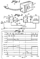
- FIG. 3 provides exemplary voltage waveforms to illustrate the operation of the external DC power supply 10.
- voltage levels are represented in Kilovolts versus time in seconds.
- a first line labelled AC LINE INPUT illustrates near opposite ends a normal sinusoidal AC line voltage with a central zero level power outage portion shown.
- V D the corresponding voltage levels at V D in FIG. 2 across the OUTPUT of the external DC power supply 10 are illustrated.
- voltage levels are represented in volts versus time in seconds.
- a line labelled V C represents the corresponding supply voltage
- a line labelled IB represents the corresponding battery supply current applied to the DC-to-DC converter 39 indicated at V C across the filtering capacitor 38 in FIG. 2.
- External DC power supply 40 uses an alternative rectifier than the bridge rectifier 20 in FIG. 1.
- External DC power supply 40 includes a split phase transformer 42 in parallel with a pair of oppositely polled diodes 44 and 46, as shown.
- the series connected battery 32 and diode 34 is connected between a center tap of the split phase transformer 42 and at the anode junction connection of the diodes 32 and 34 to provide similar backup power functions as the external DC power supply 20.
- External DC power supply 56 further includes a transformer 58 having its primary winding 60 connected across LINE and NEUTRAL of the AC line input voltage.
- the secondary winding 62 of the transformer 58 provides an AC voltage supply to a battery charger 64.
- the battery charger 64 is connected in parallel with a battery 66 for charging the battery 66.
- the battery 66 is connected in series with a DC converter 68 and diode 34 for providing the desired voltage level at the junction V D .
- a 12 volt battery 66 can be used with the DC converter 68 adapted for providing a 120 volt DC level at its output.
- FIG. 6 there is shown an alternative external DC power supply generally designated by the reference numeral 76 together with a supported device 20A including a voltage doubler arrangement.
- External DC power supply 76 is similar to the supply 56 of FIG. 5 further adapted for selective operation with either an AC line input supply of 120 volts nominal or 240 volts nominal.
- the external DC power supply 76 further includes a DC converter 69 providing double the voltage amplitude of the DC converter 68 of FIG. 5.
- the DC voltage output of converter 69 can be about 240 volts as compared to a DC voltage output of 120 volts for the DC converter 68.
- the external DC power supply 76 further includes a manually operable switch 78 for use in conjunction with a manually operable switch 80 provided within the supported device 20.
- a pair of additional capacitors 82 and 84 of the external DC power supply 76 are connected in series across the center connections of the bridge rectifier 22.
- Nominal voltage selecting switch 78 is connected between the junction of capacitors 82 and 84 and the NEUTRAL of the AC line input.
- the supported device 20A includes a pair of capacitors 86 and 88 in conjunction with the switch 80, as shown.
- the nominal voltage selecting switch 78 is closed for an AC line input supply of 120 volts nominal with the supported device switch 80 in the closed position.
- the nominal voltage selecting switch 78 is opened for an AC line input supply of 240 volts nominal with the supported device switch in the open position.
- FIG. 7 there is shown an alternative external DC power supply generally designated by the reference numeral 90 together with a supported device 20B adapted for 3-phase operation.
- the external DC power supply 90 includes a 3-phase AC plug 92 for connection with the 3-phase AC line supply.
- a 3-phase AC plug 94 of the supported device 20B is connected to a corresponding receptacle 96 of the external DC power supply 90, as shown.
- the external DC power supply 90 includes a 3-phase bridge rectifier 98 including six diodes 100, 102, 104, 106, 108 and 110.
- the external DC power supply 90 includes a series connected combination of a battery 112 and a diode 114 connected across the 3-phase bridge rectifier 98.
- the supported device 20B includes a 3-phase bridge 118 including six diodes 120, 122, 124, 126, 128 and 130 with a filtering capacitor 132 connected across the 3-phase bridge 118.
- the parallel combination of the series connected battery 112 and diode 114 and the 3-phase rectifier 98 is connected via receptacle 96 and 3-phase plug 94 to the 3-phase bridge 118, as shown.
- the external DC power supply 90 provides similar backup power functions for 3-phase operation as the external DC power supply 20.
- External DC power supply 136 includes a capacitor 138 replacing the battery 32 and diode 34 combination of FIG. 1.
- the capacitor 138 provides a backup current source for a time period of a selected number of cycles proportional to its energy storage capacity.
- a 250 volt or 450 volt rated capacitor having a capacitance rating in a range between 250-10,000 microFarad advantageously is used for the capacitor 138.
- Various commercially available capacitors can be used for the capacitor 138, for example, such as, an aluminum electrolytic type Series 36DX sold by Sprague, Inc.
- External DC power supply 146 further includes a resistor 148 and a diode 150 in combination with the capacitor 138, as shown.
- the resistor 148 provides a path for slowly charging the capacitor 138 during normal operation of the AC line input.
- the capacitor 138 is discharged through the diode 150 when the AC line input power fails.
- External DC power supply 156 includes a second bridge rectifier 158 including four diodes 160, 162, 164 and 166.
- the bridge rectifier 158 is connected at its input to an alternative AC power source.
- the series connected combination of the battery 32 and diode 34 is connected across the + and - center connections of the bridge rectifier 158.
- External DC power supply 156 provides backup battery power to the supported device 20 in the event of failure of both the normal AC line power and the alternative AC power source.
- the normal AC line power and the alternative AC power source are not required to be synchronous or to have the same frequency.
Abstract
Description
- The present invention relates generally to standby power systems for supplying power to a supported system or device, such as a computer or telephone switching equipment when an AC (alternating current) normal operating supply has a power outage or the AC line voltage drops below a predetermined and adjustable minimum voltage. More particularly, the present invention relates to an external backup power system for supplying DC (direct current) backup power without requiring modification of the supported device.
- Backup power systems are increasingly used for applications, such as computer, security, data processing and communications equipment to avoid interruptions resulting from a primary AC power source. Various arrangements have been employed to provide a backup or standby power supply.
- Standby supply systems are disclosed in United States patents 3,790,822; 4,401,895; 4,327,298; 4,313,060; 4,362,951; 4,366,389; 4,395,639; 4,400,626; 4,647,787; 4,468,571 and 4,885,521. Disadvantages of the known arrangements include complexity, expense and unreliability. Many of the known arrangements require modifications and/or direct wiring interconnections within the power supply circuit of the supported device, such as disclosed by United States patents 4,401,895; 4,327,298 and 4,885,521.
- United States patent 4,313,060 discloses a continuous-type uninterruptible power supply including a controlled ferroresonant regulator and rectifier combination supplying independent DC outputs and driving an inverter. The inverter is arranged to provide a plurality of AC and DC outputs.
- U.S. patent 4,885,521 discloses a supplemental battery backup power system for computer systems that, in the absence of AC line voltage, supplies DC voltages directly to the computer DC power bus and by-passes the internal, AC, computer power supply. A special harness assembly connects the supplemental battery backup power system with a personal computer. The harness assembly must be adapted for an output array of voltages and currents in a specific, physical arrangement of a power input connector for a specific computer processing unit to which the backup power is supplied.
- This in mind the main object of the present invention is to provide an external backup power system capable of simply, effectively and reliably supplying DC (direct current) backup power to a supported device without requiring any modification of the supported device, and capable of being used with various devices and being inexpensive.
- As a whole, the invention as claimed is to supply DC power to an AC power supply of the supported system when a primary AC operating supply drops below a predetermined minimum voltage (which may be adjustable). It does not require any special wiring or modification of the supported AC power supply and it does not affect normal operation when backup power is not needed. More precisely, the backup DC power can be supplied directly to an AC line input of the AC power supply of the supported system instantaneously without requiring switching between the AC supply and the backup DC supply.
- In a preferred embodiment the invention provides an external DC (direct current) power supply for supplying backup DC power to a supported device having an AC input connector. The power supply includes an AC (alternating current) voltage source. A voltage rectifier is coupled to the AC voltage source for rectifying the AC voltage source. An energy storage device coupled in parallel to the voltage rectifier provides a predetermined DC voltage threshold level. A connector of the external DC power supply applies a power output of the parallel combination of the voltage rectifier and the energy storage device to the AC input connector of the supported device.
- The present invention, together with the above and other objects and advantages, may best be understood from the following detailed description of the embodiment of the invention illustrated in the drawing, wherein:
- FIG. 1 is a perspective view of an external DC power supply in accordance with the principles of the present invention;
- FIG. 2 is an electrical schematic diagram representation of the external DC power supply of FIG. 1 together with an AC power supply of a supported system;
- FIG. 3 is chart providing exemplary voltage waveforms to illustrate how operating power is supplied by the external DC power supply of FIG. 1;
- FIGS. 4-10 are electrical schematic diagram representations of alternative external DC power supplies arranged in accordance with the principles of the present invention.
- Referring now to the drawing, in FIGS. 1 and 2 there is illustrated an external DC power supply generally designated by the
reference numeral 10. The externalDC power supply 10 is a separate module including ahousing 12. At its INPUT, the externalDC power supply 10 includes anAC input plug 14 for connecting to a primary AC line input and at its OUTPUT, the externalDC power supply 10 includes anAC output receptacle 16 for connecting to anAC input plug 18 of a supported device generally designated as 20. Additionally, a safety adapter (not shown) could be used between anonstandard output receptacle 16 and theAC input plug 18 to prevent use of thesupply 10 by a non-compatibledevice 20. - As shown in FIG. 2, the
DC power supply 10 includes abridge rectifier 22 including fourdiodes battery 32 and adiode 34 connected across the + and - center connections of thebridge rectifier 22. At the junction VD ofdiode 34 and the + center connection of thebridge rectifier 22, a predetermined DC voltage threshold level or amplitude is selectively provided by the rating of thebattery 32.Battery 32 supplies battery current only when the RMS value of the AC line input supply drops below the predetermined threshold amplitude at junction VD as illustrated in FIG. 3. - Although various different arrangements can be used within the supported device, the conventional source of AC line voltage is full-wave rectified at its input to provide a DC voltage. Typically, the supported device includes a
bridge rectifier 36 including four diodes, as shown. Therectifier 36 is connected in parallel with afiltering capacitor 38 providing a rectified DC voltage input VC to a DC-to-DC converter 39. Many different types of DC-to-DC converters are used to provide an array of DC output voltages at various current to be distributed within a particular supporteddevice 20. - Any suitably rated diode can be used for the
diodes battery 32 that can either be of the rechargeable type or primary cells to be thrown away when discharged. For examples, rechargeable lead-acid or gel-type cells, such as sold by Panasonic Corp. and others can be used for thebattery 32. Thebattery 32 can include multiple 12 volt units that can be stacked to provide the selected voltage VD in conjunction with thediode 34. - FIG. 3 provides exemplary voltage waveforms to illustrate the operation of the external
DC power supply 10. At the top chart, voltage levels are represented in Kilovolts versus time in seconds. A first line labelled AC LINE INPUT illustrates near opposite ends a normal sinusoidal AC line voltage with a central zero level power outage portion shown. Next at a line labelled VD, the corresponding voltage levels at VD in FIG. 2 across the OUTPUT of the externalDC power supply 10 are illustrated. At the lower chart, voltage levels are represented in volts versus time in seconds. In the lower chart a line labelled VC represents the corresponding supply voltage, and a line labelled IB represents the corresponding battery supply current applied to the DC-to-DC converter 39 indicated at VC across thefiltering capacitor 38 in FIG. 2. As shown, normally no DC current is supplied by thebattery 32. This is because the supportedpower supply 20 draws its current only at the peaks of the AC cycle. Following a power outage when the voltage VC drops to a selected threshold level, DC current is supplied essentially instantaneously by thebattery 32 through thediode 34 without requiring any switching between the conventional source of AC line voltage and the externalDC power supply 10. - In FIG. 4, there is shown an alternative external DC power supply, generally designated by the
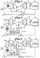
reference numeral 40, together with the supporteddevice 20. ExternalDC power supply 40 uses an alternative rectifier than thebridge rectifier 20 in FIG. 1. The same reference numerals are used in FIG. 4 for similar components of FIG. 1. ExternalDC power supply 40 includes asplit phase transformer 42 in parallel with a pair of oppositely polleddiodes battery 32 anddiode 34 is connected between a center tap of thesplit phase transformer 42 and at the anode junction connection of thediodes DC power supply 20. - In FIG. 5, there is shown an alternative external DC power supply generally designated by the reference numeral 56 together with the supported
device 20. The same reference numerals are used in FIG. 5 for similar components of FIG. 1. External DC power supply 56 further includes atransformer 58 having itsprimary winding 60 connected across LINE and NEUTRAL of the AC line input voltage. Thesecondary winding 62 of thetransformer 58 provides an AC voltage supply to abattery charger 64. Thebattery charger 64 is connected in parallel with abattery 66 for charging thebattery 66. Thebattery 66 is connected in series with aDC converter 68 anddiode 34 for providing the desired voltage level at the junction VD. For example, a 12volt battery 66 can be used with theDC converter 68 adapted for providing a 120 volt DC level at its output. - In FIG. 6, there is shown an alternative external DC power supply generally designated by the
reference numeral 76 together with a supporteddevice 20A including a voltage doubler arrangement. The same reference numerals are used in FIG. 6 for similar components of FIGS. 1 and 5. ExternalDC power supply 76 is similar to the supply 56 of FIG. 5 further adapted for selective operation with either an AC line input supply of 120 volts nominal or 240 volts nominal. The externalDC power supply 76 further includes aDC converter 69 providing double the voltage amplitude of theDC converter 68 of FIG. 5. For example, the DC voltage output ofconverter 69 can be about 240 volts as compared to a DC voltage output of 120 volts for theDC converter 68. The externalDC power supply 76 further includes a manuallyoperable switch 78 for use in conjunction with a manually operable switch 80 provided within the supporteddevice 20. A pair ofadditional capacitors DC power supply 76 are connected in series across the center connections of thebridge rectifier 22. Nominalvoltage selecting switch 78 is connected between the junction ofcapacitors device 20A includes a pair ofcapacitors - In operation the nominal
voltage selecting switch 78 is closed for an AC line input supply of 120 volts nominal with the supported device switch 80 in the closed position. The nominalvoltage selecting switch 78 is opened for an AC line input supply of 240 volts nominal with the supported device switch in the open position. - In FIG. 7, there is shown an alternative external DC power supply generally designated by the
reference numeral 90 together with a supporteddevice 20B adapted for 3-phase operation. At its input, the externalDC power supply 90 includes a 3-phase AC plug 92 for connection with the 3-phase AC line supply. A 3-phase AC plug 94 of the supporteddevice 20B is connected to a correspondingreceptacle 96 of the externalDC power supply 90, as shown. The externalDC power supply 90 includes a 3-phase bridge rectifier 98 including sixdiodes DC power supply 90 includes a series connected combination of abattery 112 and adiode 114 connected across the 3-phase bridge rectifier 98. - The supported
device 20B includes a 3-phase bridge 118 including sixdiodes filtering capacitor 132 connected across the 3-phase bridge 118. The parallel combination of the series connectedbattery 112 anddiode 114 and the 3-phase rectifier 98 is connected viareceptacle 96 and 3-phase plug 94 to the 3-phase bridge 118, as shown. The externalDC power supply 90 provides similar backup power functions for 3-phase operation as the externalDC power supply 20. - In FIG. 8, there is shown an alternative external DC power supply generally designated by the
reference numeral 136 together with the supporteddevice 20. The same reference numerals are used in FIG. 8 for similar components of FIG. 1. ExternalDC power supply 136 includes acapacitor 138 replacing thebattery 32 anddiode 34 combination of FIG. 1. Thecapacitor 138 provides a backup current source for a time period of a selected number of cycles proportional to its energy storage capacity. A 250 volt or 450 volt rated capacitor having a capacitance rating in a range between 250-10,000 microFarad advantageously is used for thecapacitor 138. Various commercially available capacitors can be used for thecapacitor 138, for example, such as, an aluminum electrolytic type Series 36DX sold by Sprague, Inc. - In FIG. 9, there is shown an alternative external DC power supply generally designated by the
reference numeral 146 together with the supporteddevice 20. The same reference numerals are used in FIG. 9 for similar components of FIGS. 1 and 8. ExternalDC power supply 146 further includes aresistor 148 and adiode 150 in combination with thecapacitor 138, as shown. Theresistor 148 provides a path for slowly charging thecapacitor 138 during normal operation of the AC line input. Thecapacitor 138 is discharged through thediode 150 when the AC line input power fails. - In FIG. 10, there is shown an alternative external DC power supply generally designated by the
reference numeral 156 together with the supporteddevice 20. The same reference numerals are used in FIG. 10 for similar components of FIG. 1. ExternalDC power supply 156 includes asecond bridge rectifier 158 including fourdiodes bridge rectifier 158 is connected at its input to an alternative AC power source. The series connected combination of thebattery 32 anddiode 34 is connected across the + and - center connections of thebridge rectifier 158. ExternalDC power supply 156 provides backup battery power to the supporteddevice 20 in the event of failure of both the normal AC line power and the alternative AC power source. The normal AC line power and the alternative AC power source are not required to be synchronous or to have the same frequency. - In summary, multiple external DC power supply arrangements have been provided for simply and economically providing backup power for various types of supported devices. A significant advantage of all of these external DC power supplies is that the need for access to wiring within a particular supported device is eliminated.
Claims (13)
- An external DC (direct current) power supply (10) for supplying backup DC power to a supported device having an AC input connector(18), said power supply comprising:
an AC (alternating current) voltage source;
voltage rectifier means (22) coupled to said AC voltage source for rectifying said AC voltage source;
energy storage means (32) coupled to said voltage rectifier means (22) for providing a predetermined DC voltage threshold level; and
connector means (16) for applying a power output of said parallel combination of said rectifier means and said energy storage means to the AC input connector (18) of the supported device. - An external DC power supply (10) as recited in claim 1 wherein said voltage rectifier means (22) is a full-wave rectifier.
- An external DC power supply (10) as recited in claim 1 wherein said voltage rectifier means (22) includes a split phase transformer connected in parallel with a pair of oppositely polled diodes.
- An external DC power supply (10) as recited in claim 1 wherein said an AC (alternating current) voltage source is a 3-phase AC line supply and said voltage rectifier means includes a six diode bridge rectifier (98).
- An external DC power supply (10) as recited in claim 1 wherein the supported device includes a voltage doubler arrangement and said external DC power supply (76) further comprises a voltage doubler arrangement (69).
- An external DC power supply (10) as recited in claim 5 wherein said voltage rectifier means (22) is a bridge rectifier and wherein said voltage doubler arrangement of said external DC power supply includes a switch (78) moveable between an opened position and a closed position, series connected capacitance means (80, 82) connected in parallel with said energy storage means (66) and connected between + and - center connections of said bridge rectifier (22); and said switch connected between a junction of said capacitance means (80, 82) and said + center connection.
- An external DC power supply (10) as recited in claim 9 wherein said energy storage means (32) includes a diode (34) connected in series with said battery, said voltage rectifier means (22) is a diode bridge rectifier and said series connected battery and diode is connected across an output of said diode bridge rectifier.
- An external DC power supply as recited in claim 1 wherein said energy storage means includes a capacitor (138).
- An external DC power supply (10) as recited in claim 11 further comprising a parallel combination of a resistor (148) and a diode (150) connected in series with said capacitor (138).
- An external DC power supply (10) as recited in claim 12 wherein said voltage rectifier means is a diode bridge rectifier (22) and wherein said series combination of said capacitor (138) and said resistor (148) and diode (150) is connected across an output of said diode bridge rectifier (22).
- An external DC power supply as recited in claim 1 wherein said connector means comprises an AC voltage receptacle providing GROUND, LINE and NEUTRAL connections.
- An external DC power supply (10) as recited in claim 1 further comprising a housing (12).
- An external DC power supply (10) as recited in claim 12, wherein said housing (12) accommodates said voltage rectifier means (22) as well as said energy storage means (32), and wherein said connector means (16) is associated to said housing, thus to form a unitary device.
Applications Claiming Priority (2)
| Application Number | Priority Date | Filing Date | Title |
|---|---|---|---|
| US57895290A | 1990-09-07 | 1990-09-07 | |
| US578952 | 1990-09-07 |
Publications (3)
| Publication Number | Publication Date |
|---|---|
| EP0476431A2 true EP0476431A2 (en) | 1992-03-25 |
| EP0476431A3 EP0476431A3 (en) | 1994-03-23 |
| EP0476431B1 EP0476431B1 (en) | 1997-01-29 |
Family
ID=24314997
Family Applications (1)
| Application Number | Title | Priority Date | Filing Date |
|---|---|---|---|
| EP91114927A Expired - Lifetime EP0476431B1 (en) | 1990-09-07 | 1991-09-04 | External backup power supply |
Country Status (5)
| Country | Link |
|---|---|
| US (1) | US5874788A (en) |
| EP (1) | EP0476431B1 (en) |
| AU (1) | AU642293B2 (en) |
| CA (1) | CA2050829C (en) |
| DE (1) | DE69124442T2 (en) |
Cited By (2)
| Publication number | Priority date | Publication date | Assignee | Title |
|---|---|---|---|---|
| WO1996022626A1 (en) * | 1995-01-18 | 1996-07-25 | Magnum Power Solutions Limited | Partitioned uninterruptible power supplies |
| AT406920B (en) * | 1997-05-30 | 2000-10-25 | Siemens Ag Oesterreich | POWER SUPPLY |
Families Citing this family (27)
| Publication number | Priority date | Publication date | Assignee | Title |
|---|---|---|---|---|
| TW426271U (en) * | 1999-02-03 | 2001-03-11 | Delta Electronics Inc | External backup power supply |
| US6697265B2 (en) * | 2001-05-23 | 2004-02-24 | Advanced Energy Industries, Inc. | Wide range DC power supply utilizing voltage doubling output capacitors and inductive choke to extend full power load impedance range |
| US7378756B2 (en) * | 2006-07-06 | 2008-05-27 | Singer Troy W | Battery backup electric plug with female plug |
| US8067856B2 (en) * | 2008-09-04 | 2011-11-29 | Intel Corporation | Power management system |
| US8302416B2 (en) * | 2009-03-02 | 2012-11-06 | Rocky Research | Liquid refrigerant composite cooling system |
| CN101902056B (en) * | 2009-06-01 | 2015-06-17 | Ge医疗系统环球技术有限公司 | Uninterruptable power supply and method for saving electricity of same |
| US8193660B2 (en) * | 2009-07-27 | 2012-06-05 | Rocky Research | HVAC/R system having power back-up system with a DC-DC converter |
| US9160258B2 (en) | 2009-07-27 | 2015-10-13 | Rocky Research | Cooling system with increased efficiency |
| US20110018350A1 (en) * | 2009-07-27 | 2011-01-27 | Rocky Research | Power back-up system with a dc-dc converter |
| US20110018474A1 (en) * | 2009-07-27 | 2011-01-27 | Rocky Research | Electromechanical system having a variable frequency drive power supply for 3-phase and 1-phase motors |
| US8278778B2 (en) * | 2009-07-27 | 2012-10-02 | Rocky Research | HVAC/R battery back-up power supply system having a variable frequency drive (VFD) power supply |
| US8299646B2 (en) * | 2009-07-27 | 2012-10-30 | Rocky Research | HVAC/R system with variable frequency drive (VFD) power supply for multiple motors |
| US20110016915A1 (en) * | 2009-07-27 | 2011-01-27 | Rocky Research | High efficiency dc compressor and hvac/r system using the compressor |
| US8299653B2 (en) * | 2009-07-27 | 2012-10-30 | Rocky Research | HVAC/R system with variable frequency drive power supply for three-phase and single-phase motors |
| JP5274504B2 (en) * | 2010-04-09 | 2013-08-28 | 三菱電機株式会社 | Automotive power system |
| TW201227239A (en) * | 2010-12-20 | 2012-07-01 | Hon Hai Prec Ind Co Ltd | Power system for container data center |
| US9071078B2 (en) | 2011-01-24 | 2015-06-30 | Rocky Research | Enclosure housing electronic components having hybrid HVAC/R system with power back-up |
| US9228750B2 (en) | 2011-01-24 | 2016-01-05 | Rocky Research | HVAC/R system with multiple power sources and time-based selection logic |
| KR101797230B1 (en) * | 2011-02-09 | 2017-11-13 | 삼성전자주식회사 | Circuit for dc appliance |
| US20130285449A1 (en) * | 2012-04-26 | 2013-10-31 | Hamilton Sundstrand Corporation | System and method for providing hold-up power to a load |
| USD743890S1 (en) * | 2014-08-27 | 2015-11-24 | Shenzhen Longood Intelligent Electric Co., Ltd | Electronic ballast |
| USD780691S1 (en) | 2015-05-20 | 2017-03-07 | Ip Holdings, Llc | Remote ballast |
| RU178775U1 (en) * | 2016-12-09 | 2018-04-19 | Общество С Ограниченной Ответственностью "Ультраконденсаторы Феникс" | UNINTERRUPTIBLE POWER SUPPLY SYSTEM BASED ON FREQUENCY CONVERTERS |
| WO2018107412A1 (en) | 2016-12-15 | 2018-06-21 | 万喻 | Low-radiation uninterruptible power supply |
| USD855238S1 (en) | 2017-10-27 | 2019-07-30 | Hgci, Inc. | Ballast |
| USD871654S1 (en) | 2017-10-30 | 2019-12-31 | Hgci, Inc. | Light fixture |
| CN112436494B (en) * | 2020-11-26 | 2023-03-31 | 云南电网有限责任公司电力科学研究院 | Circuit breaker fault backup protection method suitable for high-voltage direct-current power grid |
Citations (2)
| Publication number | Priority date | Publication date | Assignee | Title |
|---|---|---|---|---|
| EP0077531A1 (en) * | 1981-10-20 | 1983-04-27 | Société Anonyme dite SAFT | Charging device for a group of batteries, especially of buffer batteries fed by a limited power supply |
| EP0079462A2 (en) * | 1981-10-16 | 1983-05-25 | CEAG Licht- und Stromversorgungstechnik GmbH | Fluorescent lamp safety lighting |
Family Cites Families (20)
| Publication number | Priority date | Publication date | Assignee | Title |
|---|---|---|---|---|
| DE1965315B2 (en) * | 1969-12-29 | 1972-12-14 | Siemens AG, 1000 Berlin u 8000 München | CIRCUIT ARRANGEMENT FOR UNINTERRUPTED SWITCHING FROM AN OPERATING POWER SUPPLY DEVICE TO A SUBSTITUTE POWER SUPPLY DEVICE |
| GB1333918A (en) * | 1970-05-02 | 1973-10-17 | Lucas Industries Ltd | Instruments for checking the operation of earth leakage circuit breakers |
| JPS5334491Y2 (en) * | 1972-02-19 | 1978-08-24 | ||
| US4065676A (en) * | 1976-06-02 | 1977-12-27 | Honeywell Inc. | Battery backup for AC powered DC supply |
| SE419015B (en) * | 1979-11-01 | 1981-07-06 | Jungner Ab Nife | PROCEDURE FOR OPERATION OF AN INTERRUPTED POWER SUPPLY AND INTERRUPTED POWER SUPPLY FOR IMPLEMENTATION OF THE PROCEDURE |
| US4327298A (en) * | 1979-12-14 | 1982-04-27 | Borg-Warner Corporation | Battery backup system for a microcomputer |
| US4313060A (en) * | 1980-02-15 | 1982-01-26 | Bell Telephone Laboratories, Incorporated | Uninterruptible power supply with load regulation of standby voltage source |
| JPS5920261B2 (en) * | 1980-05-07 | 1984-05-11 | 株式会社東芝 | Uninterruptible power system |
| US4362951A (en) * | 1980-12-10 | 1982-12-07 | Control Technology | Cycle charge standby power system |
| US4366389A (en) * | 1981-07-13 | 1982-12-28 | Reliance Electric Company | Continuously operating standby A-C power system |
| US4400626A (en) * | 1982-02-24 | 1983-08-23 | Rockwell International Corporation | Power distribution system with means for sensing emergency condition and reducing standby power |
| US4401895A (en) * | 1982-09-20 | 1983-08-30 | Reliance Electric Company | Supply for providing uninterruptible d-c power to a load |
| US4468571A (en) * | 1982-10-27 | 1984-08-28 | Saft America, Inc. | Standby power system |
| US4560887A (en) * | 1983-12-22 | 1985-12-24 | Northern Telecom Limited | Standby power supply |
| US4627483A (en) * | 1984-01-09 | 1986-12-09 | Visual Information Institute, Inc. | Heat pump control system |
| US4647787A (en) * | 1985-02-04 | 1987-03-03 | Gte Communication Systems Corp. | Backup battery power supply for microprocessor based telephones |
| US4885521A (en) * | 1985-08-26 | 1989-12-05 | Applied Research & Technology, Inc. | Unique computer power system with backup power |
| US4884013A (en) * | 1988-01-15 | 1989-11-28 | Sherwood Medical Company | Motor unit for a fluid pump and method of operation |
| US4837672A (en) * | 1988-08-30 | 1989-06-06 | Storage Technology Corporation | Switched mode power supply |
| US5111058A (en) * | 1990-05-23 | 1992-05-05 | Martin Richard A | Circuit for sustaining power supply output following momentary interruption of commercial a.c. power |
-
1991
- 1991-09-04 EP EP91114927A patent/EP0476431B1/en not_active Expired - Lifetime
- 1991-09-04 DE DE69124442T patent/DE69124442T2/en not_active Expired - Fee Related
- 1991-09-06 AU AU83722/91A patent/AU642293B2/en not_active Ceased
- 1991-09-06 CA CA002050829A patent/CA2050829C/en not_active Expired - Fee Related
-
1993
- 1993-04-12 US US08/046,127 patent/US5874788A/en not_active Expired - Fee Related
Patent Citations (2)
| Publication number | Priority date | Publication date | Assignee | Title |
|---|---|---|---|---|
| EP0079462A2 (en) * | 1981-10-16 | 1983-05-25 | CEAG Licht- und Stromversorgungstechnik GmbH | Fluorescent lamp safety lighting |
| EP0077531A1 (en) * | 1981-10-20 | 1983-04-27 | Société Anonyme dite SAFT | Charging device for a group of batteries, especially of buffer batteries fed by a limited power supply |
Non-Patent Citations (1)
| Title |
|---|
| EDN ELECTRICAL DESIGN NEWS. vol. 28, no. 13 , June 1983 , NEWTON, MASSACHUSETTS US pages 143 - 148 C. SMALL 'Auxiliary battery inputs transform switchers into uninterruptible power supplies' * |
Cited By (2)
| Publication number | Priority date | Publication date | Assignee | Title |
|---|---|---|---|---|
| WO1996022626A1 (en) * | 1995-01-18 | 1996-07-25 | Magnum Power Solutions Limited | Partitioned uninterruptible power supplies |
| AT406920B (en) * | 1997-05-30 | 2000-10-25 | Siemens Ag Oesterreich | POWER SUPPLY |
Also Published As
| Publication number | Publication date |
|---|---|
| EP0476431A3 (en) | 1994-03-23 |
| AU8372291A (en) | 1992-03-12 |
| DE69124442D1 (en) | 1997-03-13 |
| EP0476431B1 (en) | 1997-01-29 |
| CA2050829C (en) | 2002-03-05 |
| CA2050829A1 (en) | 1992-03-08 |
| US5874788A (en) | 1999-02-23 |
| DE69124442T2 (en) | 1997-07-17 |
| AU642293B2 (en) | 1993-10-14 |
Similar Documents
| Publication | Publication Date | Title |
|---|---|---|
| US5874788A (en) | External backup power supply | |
| US5781422A (en) | Uninterruptible power supply with AC and DC power inputs | |
| US5289045A (en) | Uninterruptible power supply | |
| EP0904621B1 (en) | Modular power management system and method | |
| KR101175576B1 (en) | Static energising system for a generator and method for operation of such an energising system | |
| US7679943B2 (en) | Uninterruptable power supply | |
| EP1800382B1 (en) | Method and apparatus for providing uninterruptible power | |
| US6614130B2 (en) | Balanced modular power management system and method | |
| US4642475A (en) | Uninterruptible power supply | |
| IE51606B1 (en) | Power supply system for a plurality of electronic equipments | |
| CN114256956B (en) | DC power supply system | |
| NO310997B1 (en) | Power supply system for auxiliary equipment in a pump station with remote power supply | |
| US11342788B1 (en) | System and method for in-rack generation of alternating current voltage during power grid outages | |
| GB2241394A (en) | Uninterruptible power supply system | |
| CA1213641A (en) | Standby power supply | |
| JPS62250876A (en) | Voltage type inverter unit | |
| KR200300983Y1 (en) | High Efficient Direct Current Uninterruptible Power Supply Apparatus | |
| JPS62262623A (en) | Non-interruption source system | |
| HU185578B (en) | No-break d.c. current supply apparatus |
Legal Events
| Date | Code | Title | Description |
|---|---|---|---|
| PUAI | Public reference made under article 153(3) epc to a published international application that has entered the european phase |
Free format text: ORIGINAL CODE: 0009012 |
|
| AK | Designated contracting states |
Kind code of ref document: A2 Designated state(s): DE FR GB |
|
| PUAL | Search report despatched |
Free format text: ORIGINAL CODE: 0009013 |
|
| AK | Designated contracting states |
Kind code of ref document: A3 Designated state(s): DE FR GB |
|
| 17P | Request for examination filed |
Effective date: 19940915 |
|
| 17Q | First examination report despatched |
Effective date: 19941107 |
|
| GRAG | Despatch of communication of intention to grant |
Free format text: ORIGINAL CODE: EPIDOS AGRA |
|
| GRAH | Despatch of communication of intention to grant a patent |
Free format text: ORIGINAL CODE: EPIDOS IGRA |
|
| GRAH | Despatch of communication of intention to grant a patent |
Free format text: ORIGINAL CODE: EPIDOS IGRA |
|
| GRAA | (expected) grant |
Free format text: ORIGINAL CODE: 0009210 |
|
| AK | Designated contracting states |
Kind code of ref document: B1 Designated state(s): DE FR GB |
|
| REF | Corresponds to: |
Ref document number: 69124442 Country of ref document: DE Date of ref document: 19970313 |
|
| ET | Fr: translation filed | ||
| PLBE | No opposition filed within time limit |
Free format text: ORIGINAL CODE: 0009261 |
|
| STAA | Information on the status of an ep patent application or granted ep patent |
Free format text: STATUS: NO OPPOSITION FILED WITHIN TIME LIMIT |
|
| 26N | No opposition filed | ||
| PGFP | Annual fee paid to national office [announced via postgrant information from national office to epo] |
Ref country code: GB Payment date: 20010807 Year of fee payment: 11 |
|
| PGFP | Annual fee paid to national office [announced via postgrant information from national office to epo] |
Ref country code: FR Payment date: 20010831 Year of fee payment: 11 |
|
| PGFP | Annual fee paid to national office [announced via postgrant information from national office to epo] |
Ref country code: DE Payment date: 20010927 Year of fee payment: 11 |
|
| REG | Reference to a national code |
Ref country code: GB Ref legal event code: IF02 |
|
| PG25 | Lapsed in a contracting state [announced via postgrant information from national office to epo] |
Ref country code: GB Free format text: LAPSE BECAUSE OF NON-PAYMENT OF DUE FEES Effective date: 20020904 |
|
| PG25 | Lapsed in a contracting state [announced via postgrant information from national office to epo] |
Ref country code: DE Free format text: LAPSE BECAUSE OF NON-PAYMENT OF DUE FEES Effective date: 20030401 |
|
| GBPC | Gb: european patent ceased through non-payment of renewal fee |
Effective date: 20020904 |
|
| PG25 | Lapsed in a contracting state [announced via postgrant information from national office to epo] |
Ref country code: FR Free format text: LAPSE BECAUSE OF NON-PAYMENT OF DUE FEES Effective date: 20030603 |
|
| REG | Reference to a national code |
Ref country code: FR Ref legal event code: ST |