EP0476191A1 - Filter press - Google Patents
Filter press Download PDFInfo
- Publication number
- EP0476191A1 EP0476191A1 EP90310183A EP90310183A EP0476191A1 EP 0476191 A1 EP0476191 A1 EP 0476191A1 EP 90310183 A EP90310183 A EP 90310183A EP 90310183 A EP90310183 A EP 90310183A EP 0476191 A1 EP0476191 A1 EP 0476191A1
- Authority
- EP
- European Patent Office
- Prior art keywords
- filter
- cloths
- plates
- filter cloths
- filter plates
- Prior art date
- Legal status (The legal status is an assumption and is not a legal conclusion. Google has not performed a legal analysis and makes no representation as to the accuracy of the status listed.)
- Granted
Links
Images


Classifications
-
- B—PERFORMING OPERATIONS; TRANSPORTING
- B01—PHYSICAL OR CHEMICAL PROCESSES OR APPARATUS IN GENERAL
- B01D—SEPARATION
- B01D25/00—Filters formed by clamping together several filtering elements or parts of such elements
- B01D25/12—Filter presses, i.e. of the plate or plate and frame type
- B01D25/172—Plate spreading means
-
- B—PERFORMING OPERATIONS; TRANSPORTING
- B01—PHYSICAL OR CHEMICAL PROCESSES OR APPARATUS IN GENERAL
- B01D—SEPARATION
- B01D25/00—Filters formed by clamping together several filtering elements or parts of such elements
- B01D25/32—Removal of the filter cakes
- B01D25/34—Removal of the filter cakes by moving, e.g. rotating, the filter elements
-
- B—PERFORMING OPERATIONS; TRANSPORTING
- B01—PHYSICAL OR CHEMICAL PROCESSES OR APPARATUS IN GENERAL
- B01D—SEPARATION
- B01D25/00—Filters formed by clamping together several filtering elements or parts of such elements
- B01D25/32—Removal of the filter cakes
- B01D25/38—Removal of the filter cakes by moving parts, e.g. scrapers, contacting stationary filter elements sprayers
- B01D25/386—Nozzles
Definitions
- the filter press further comprises tension bearing means which are mounted on the filter plates respectively and which prevent movements of the forward ends of the filter cloths to bear the tensions for drawing out the forward ends of the filter cloths from the cloth reservoir means when the distance between the filter plates is decreased to bring the filter plates adjacent to each other into contact with each other, so that the tensions of the filter cloths are not applied to the drawing means when the distance between the filter plates is decreased.
- the tension bearing means are mounted on the filter plates respectively and prevent the movements of the forward ends of the filter cloths to bear the tensions of the filter cloths when the distance between the filter plates is changed, the tensions of the filter cloths are born by the tension bearing means and the cloth reservoir means and are not applied to slide portions between the shaft means and the drawing means.
- the filter plate 6 fixed to the frame 1 is connected to the filter plate 6 adjacent thereto by a spring 8'.
- Each of the filter plates 6 has at least one pressing plane 61 extending substantially vertically and perpendicularly to the longitudinal axes of the horizontal beams 4 so that the pressing planes 61 facing to each other are brought into contact with each other when the filter plate 6 connected to the head 3 is moved leftward by the cylinder 5.
- Filter cloths 15 extend over the pressing planes 61 respectively. Forward or upper ends 151 of the filter cloths 15 are supported by respective support bars 14 and are brought either up or down through the support bars 14 by filter cloth drawing devices described below when spaces are formed between the pressing planes 61 adjacent to each other by the movement of the cylinder 5.
- the filter cloths 15 extend over the pressing planes 61 and around guide rollers 17 or 18 fixed through brackets 20 on lower parts of the pressing plates 6 and are received or wound up by reservoir rollers 16. On periphery of each of the reservoir rollers 16, two of the filter cloths 15 are received and respective contacting surfaces for contacting with sludge are brought into contact with each other.
- Each of the reservoir rollers 16 has a central shaft and a coil spring (these are not shown in the drawings) so that a torque on the central shaft is applied to the reservoir roller 16 to draw the filter cloths 15 toward the reservoir roller 16.
- Washing pipe 19 are arranged below the guide rollers 17 and 18 respectively so that the filter cloths 15 are washed by the washing pipe 19 when the filter cloths 15 are brought up or drawn out from the reservoir roller 16.
Abstract
Description
- The present invention relates to a filter press in which sludge is compressed and dehydrated between filter cloths, or more particularly relates to a filter cloth driving means used in the filter press.
- A conventional filter press as shown, for example, in the publication of Japanese Patent Unexamined Publication No. 53-36772, comprises a plurality of movable filter plates each of which has at least one pressing surface, a guide device for guiding the filter plates in a filter plate moving direction, a plurality of filter cloths extending over the pressing surfaces respectively and being capable of moving thereover, a filter plate driving device for moving the filter plates so that the pressing surfaces adjacent to each other are brought into contact with each other through the filter cloths, a plurality of filter cloth reservoirs which are mounted on the filter plates respectively and which apply a predetermined tension to the filter cloths extending over the pressing surfaces of the filter plates so that the filter cloths are drawn toward the filter cloth reservoirs, a plurality of filter cloth tension devices which are fixed on the filter plates respectively and which draw out the filter cloths from the filter cloth reservoirs so that the filter cloths cover the pressing surfaces with the predetermined tension, shafts which engage with the filter cloth tension devices to supply a driving force to the filter cloth tension devices and on which the filter cloth tension devices are movable in a longitudinal direction of the shafts, and at least one compression device for compressing sludge inserted between the filter cloths between the pressing surfaces when the pressing surfaces adjacent to each other are brought into contact with each other.
- An object of the present invention is to provide a filter press in which pressing pressure applied to filter cloths between the pressing planes is constant over the whole of the pressing planes.
- A filter press according to the present invention, comprises
- at least two filter plates each of which has at least one pressing plane and in which a distance between the filter plates adjacent to each other is changed to bring the pressing planes adjacent to each other into contact with each other,
- guiding means which guide the filter plates in a filter plate transferring direction so that the pressing planes can be brought into contact with each other,
- at least two filter cloths which extend over the pressing planes respectively and which is capable of moving over the pressing planes,
- filter plate driving means which changes in the filter plate transferring direction the distance between the filter plates adjacent to each other to bring the pressing planes adjacent to each other into contact with each other through the filter cloths,
- cloth reservoir means which are mounted on the filter plates respectively and which apply a predetermined tension to the filter cloths so that the filter cloths are drawn toward the filter cloth reservoirs,
- drawing means which are connected to the filter plates respectively so that the drawing means move in accordance with a change of the distance between the filter plates and which draw out forward ends of the filter cloths from the cloth reservoir means so that the filter cloths extend over the pressing planes respectively,
- shaft means which engage with the drawing means to supply driving force thereto for drawing out the forward ends of the filter cloths from the cloth reservoir means and on which the drawing means can slide to move in accordance with the change of the distance between the filter plates, and
- compression means adapted for compressing sludge inserted between the filter cloths between the pressing surfaces when the pressing surfaces adjacent to each other are brought into contact with each other, wherein,
- the filter press further comprises tension bearing means which are mounted on the filter plates respectively and which prevent movements of the forward ends of the filter cloths to bear the tensions for drawing out the forward ends of the filter cloths from the cloth reservoir means when the distance between the filter plates is decreased to bring the filter plates adjacent to each other into contact with each other, so that the tensions of the filter cloths are not applied to the drawing means when the distance between the filter plates is decreased.
- In the filter press according to the present invention, since the tension bearing means are mounted on the filter plates respectively and prevent the movements of the forward ends of the filter cloths to bear the tensions of the filter cloths when the distance between the filter plates is changed, the tensions of the filter cloths are born by the tension bearing means and the cloth reservoir means and are not applied to slide portions between the shaft means and the drawing means. Therefore, frictional forces between the shaft means and the drawing means are small so that the frictional forces do not change attitudes of the filter plates connected to the drawing means, that is, the filter plates connected to the drawing means are not rotated by rotational moments generated by the frictional forces between the shaft means and the drawing means when the drawing means move in accordance with the decrease of the distance between the filter plates, so that the pressing surfaces adjacent to each other can be brought into wholely intimate contact with each other through the filter cloths and the pressing pressure applied to the filter cloths between the pressing planes is constant over the whole of the pressing planes.
-
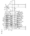
- Fig. 1 is a plane view showing a longitudinal structure of an embodiment of a filter press according to the present invention,
- Fig. 2 is a cross sectional view of the embodiment of Fig. 1,
- Fig. 3A is a plane view showing a filter cloth drawing device and a tension bearing device used in the embodiment of Fig. 1,
- Fig. 3B is an oblique projection view showing the filter cloth drawing device and the tension bearing device used in the embodiment of Fig. 1,
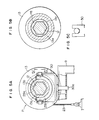
- Fig. 4 is a longitudinal sectional view showing a pulley of the filter cloth drawing device and tension bearing device of Figs. 3A and 3B,
- Fig. 5A is a cross sectional view taken along a
line 5A of Fig. 4, - Fig. 5B is a cross sectional view taken along a
line 5B of Fig. 4, - Fig. 5C is a partial plane view showing a pulley support structure in a direction indicated by an
arrow 5C of Fig. 5A, - Fig. 6A is a cross sectional view showing another embodiment of the pulley of the filter cloth drawing device and tension bearing device,
- Fig. 6B is a cross sectional view showing the other embodiment of the pulley of the filter cloth drawing device and tension bearing device,
- Fig. 7 is a diagram showing a flow chart of operation of the filter press according to the present invention,
- Fig. 8 is a schematic view showing a compression or dehydration structure of the filter press according to the present invention,
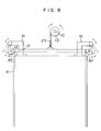
- Fig. 9 is a schematic plane view showing the other embodiments of the filter cloth drawing device and the tension bearing device used in the filter press according to the present invention,
- Fig. 10A is a schematic plane view showing the other embodiments of the filter cloth drawing device and the tension bearing device used in the filter press according to the present invention,
- Fig. 10B is a schematic plane view showing a clamp device used in the embodiment of Fig. 1 OA.
- In a filter press as shown in Figs. 1 and 2, a frame 1 and a frame 2 with a
cylinder 5 stand with a distance therebetween on a floor. Two horizontal beams extend between the frame 1 and the frame 2. A plurality offilter plates 6 are arranged between the frame 1 and the frame 2 and the most left-side one of thefilter plates 6 is fixed to the frame 1 and the most right-side one of thefilter plates 6 is fixed to ahead 3 moved in a horizontal direction by thecylinder 5 mounted on the frame 2. Thefilter plates 6 other than thefilter plates 6 fixed to the frame 1 or connected to thehead 3 are movable and guided in the horizontal direction by thehorizontal beams 4 throughrotatable guide rollers 7 which are mounted on thefilter plates 6 throughbrackets 7a to run along thehorizontal beams 4 and whose rotational axes extend horizontally and perpendicularly to longitudinal axes of thehorizontal beams 4. Between thefilter plates 6 which are other than thefilter plate 6 fixed to the frame 1 and are adjacent to each other, tie-rods 8 are supported by thebrackets 7a andbrackets 8a fixed to thefilter plates 6 so that distances between thefilter plates 6 adjacent to each other are prevented from increasing more than a predetermined degree when thefilter plate 6 connected to thehead 3 is moved rightward by thecylinder 5. Thefilter plate 6 fixed to the frame 1 is connected to thefilter plate 6 adjacent thereto by a spring 8'. Each of thefilter plates 6 has at least one pressing plane 61 extending substantially vertically and perpendicularly to the longitudinal axes of thehorizontal beams 4 so that the pressing planes 61 facing to each other are brought into contact with each other when thefilter plate 6 connected to thehead 3 is moved leftward by thecylinder 5.Filter cloths 15 extend over the pressing planes 61 respectively. Forward or upper ends 151 of thefilter cloths 15 are supported byrespective support bars 14 and are brought either up or down through thesupport bars 14 by filter cloth drawing devices described below when spaces are formed between the pressing planes 61 adjacent to each other by the movement of thecylinder 5. Thefilter cloths 15 extend over the pressing planes 61 and aroundguide rollers brackets 20 on lower parts of thepressing plates 6 and are received or wound up byreservoir rollers 16. On periphery of each of thereservoir rollers 16, two of thefilter cloths 15 are received and respective contacting surfaces for contacting with sludge are brought into contact with each other. - Each of the
reservoir rollers 16 has a central shaft and a coil spring (these are not shown in the drawings) so that a torque on the central shaft is applied to thereservoir roller 16 to draw thefilter cloths 15 toward thereservoir roller 16.Washing pipe 19 are arranged below theguide rollers filter cloths 15 are washed by thewashing pipe 19 when thefilter cloths 15 are brought up or drawn out from thereservoir roller 16. - A
driving shaft 12 extends above thehorizontal beams 4 parallel to the longitudinal axes of thehorizontal beams 4, that is, parallel to a moving direction of thefilter plates 6 and are supported bybearings 10 fixed to the frames 1 and 2 respectively. As shown in Fig. 2, vertical lines passing outer diameters ofpulleys 13 pass central points of thefilter plates 6. The drivingshaft 12 has a hexagonal cross section and is connected to amoter 11 with reduction gears through a coupling to be rotated in a normal direction or a reverse direction. Each of pairs of thepulleys 13 is mounted on aslider 13a which can slide on thedriving shaft 12 and engages therewith to be rotated thereby. Each of thesupport bars 14 of thefilter cloths 15 is suspended from thepulley 13 through awire 23 whose one end is connected to an I-shaped hook 31 fixed to a central part of thesupport bar 14 and whose another end is wound around thepulley 13 so that thefilter cloths 15 are brought up or down in accordance with a rotational direction of thepulleys 13. -
Brackets 9 are mounted on thefilter plates 6 respectively and supportrespective supporters 21 throughpins 22 whose axes extend substantially parallel to the longitudinal axes of thehorizontal beams 4 and on which thesupporters 21 are swingable as shown in Figs. 3A and 3B. Each of thesupporters 21 has anengaging portion 21 a whose central portion is connected to an end of acoil spring 26. And another end of thespring 26 is connected to avertical column 9b of thebracket 9 so that a torque is applied to each of thesupporters 21 for keeping an engaging position thereof as indicated by a continuous line in Figs. 3A and 3B. At the engaging positions of thesupporters 21, the engagingportions 21 a engage with adjustingbolts 27 fitted in thehooks 31 of the support bars 14 to bear tensions of thefilter cloths 15. Thesupporters 21 can be swung to a disengaging position bypush rods 24 which are connected to thesupporters 21 respectively and which are pushed by forward ends ofrods 32 extending radially from arocker shaft 25. Therocker shaft 25 is supported below the drivingshaft 12 in a rotatable manner byshoes 9a on thebrackets 9. When therocker shaft 25 is rotated to swing thesupporters 21 to the disengaging position indicated by a two-dot chain line in Figs. 3A and 3B, the engagingportions 21 a are disengaged from the adjustingbolts 27 of thehooks 31 so that the filter cloths 15 can be brought up or down freely. Therocker shaft 25 is driven by a not-shown cylinder through a drivingrod 25a extending radially from therocker shaft 25 as shown in Fig. 1. - As shown in Figs. 4, 5A and 5B, a
central hole 13b of each of thesliders 13a has a hexagonal shape which corresponds to the hexagonal cross- sectional shape of the drivingshaft 12 and which is slightly larger than that of the drivingshaft 12, andlongitudinal end holes 13c of each of thesliders 13a have respective circular shapes in which outer peripheries ofbushes 28 are fitted. Thebushes 28 have hexagonal holes with which the drivingshaft 12 engages in a slidable manner and are made of a low-friction synthetic resin, for example, tetrafluoride ethylene or poliacetal. Stoppers 36 fixed to side surfaces of thesliders 13a prevent thebushes 28 from moving out from theend holes 13c. - A clearance t2 between the
central hole 13b and the drivingshaft 12 is larger than a total amount of a clearance t1 between the hexagonal holes of thebushes 28 and the drivingshaft 12 and a clearance S1 between thelongitudinal end holes 13c and thebushes 28. Therefore, thesliders 13a can rotate on thebushes 28 so that thesliders 13a are rotated by the drivingshaft 12 with a backlash and thesliders 13a do not contact with the drivingshaft 12 so that thesliders 13a can slide on the drivingshaft 12 through thebushes 28. - A central annular recess extending on a plane perpendicular to longitudinal axes of the
holes sliders 13a is fitted in a rotatable manner in a circular space formed by a semicircularfirst yoke member 29 and asemicircular press member 29a. Each of thefirst yoke members 29 has pins which extend horizontally and perpendicularly to the longitudinal axes of theholes second yoke members 30, as shown in Figs. 5A and 5C. Each of thesecond yoke members 30 has apin 30a which extends vertically and which is supported in a rotatable manner on thebracket 9. Therefore, only a force parallel to the moving direction of thefilter plates 6 is applied to thesliders 13a so that thesliders 13a are moved in accordance with the movements of thefilter plates 6 through thebrackets 9, thesecond yoke members 30, thefirst yoke members 29 and thepress members 29a, but any rotational moment and any force other than the force parallel to the moving direction of thefilter plates 6 are not applied to thesliders 13a. - The filter press described above is operated as shown in Fig. 7. When the operation of the filter press is started, the
supporters 21 are moved to the disengaging position through thepush rods 24, therods 32 and therocker shaft 25 by the cylinder controlled by an electro-magnetic valve so that thehooks 31 do not engage with thesupporters 21 and the filter cloths 15 can move freely. - Subsequently, the
motor 11 rotates the drivingshaft 25 to wind up thewires 23 on thepulleys 13 so that thefilter cloths 15 are brought up through the support bars 14. When forward ends 151 of thefilter cloths 15 are brought up to a predetermined height, a stop switch stops the rotation of themotor 11 so that the heights of the forward ends 151 of thefilter cloths 15 are set at the predetermined degree. Thereafter, the cylinder controlled by the electromagnetic valve rotates therocker shaft 25 to a start position thereof so that thesupporters 21 are returned by thespring 26 to the engaging position so that the adjustingbolts 27 of thehooks 31 fixed to the support bars 14 can engages with the engagingportions 21 a of thesupporters 21. In this condition, themotor 11 rotates the driving shaft slightly to bring down the forward ends 151 of the filter cloths 15 so that thehooks 31 fixed to the support bars 14 engage with the engagingportions 21 a of thesupporters 21 connected to thefilter plates 6 through thebrackets 9 to keep the heights of the forward ends 151 of thefilter cloths 15 and to bear tensions of thefilter cloths 15. Therefore, the tensions of thefilter cloths 15 are not applied to thepulleys 13 and tensions of thewires 23 are zero. A photoelectric sensor (not shown in the drawings) examines whether the foward ends 151 of thefilter cloths 15 are held at a desired height or not. - Subsequently, the
cylinder 5 fixed to the frame 2 moves thehead 3 to bring thefilter plates 6 adjacent to each other into contact with each other so that each pair of the filter cloths 15 extending over the pressing planes 61 facing to each other is received between thefilter plates 6. Pressing pressure between thefilter plates 6 is maintained at a predetermined degree. When thefilter plates 6 are moved by thecylinder 5, thefilter plates 6 run smoothly on thehorizontal beam 4 and thesliders 13a on the drivingshaft 12 are moved through thebrackets 9 in accordance with the movements of thefilter plates 6 with a small frictional force between the drivingshaft 12 and the low-frictionsynthetic resin bushes 28. But, the tensions of the filter cloths are not applied to thesliders 13a through thepulleys 13 and thewires 23. Therefore, thesliders 13a slide smoothly on the drivingshaft 12 and attitudes of thefilter plates 6 are not changed by the tensions of thefilter cloths 15. - Subsequently, maintaining the intimate contacts between the pressing planes 61, as shown in Fig. 8,
sludge 100 is inserted into each pair of the filter cloths 15 received between the pressing planes 61 facing to each other, and high-pressure air is inserted between thefilter plates 6 anddiaphragms 101 to compress and dehydrate thesludge 100 through thefilter cloths 15. - Subsequently, the
cylinder 5 moves thehead 3 to separate thefilter plates 6 from each other with distances determined by thetie rods 8, as shown in Fig. 1. After separation of thefilter plates 6 is completed, themotor 11 rotates thepulleys 13 slightly to draw thewires 23 to bring up the forward ends 151 of thefilter cloths 15 and therocker shaft 25 is rotated to move thesupporters 21 to the disengaging position through therods 32 and thepush rods 24. Thereafter, themotor 11 rotates thepulleys 13 to bring down the forward ends 151 of the filter cloths 15 so that thefilter cloths 15 are wound up on thereservoir rollers 16 through theguide rollers filter plates 6 through thelower brackets 20. - Since the
filter cloths 15 are bent on theguide rollers filter cloths 15 are wound up on thereservoir rollers 16, the compressed anddehydrated sludge 100 is separated from thefilter cloths 15. After the forward ends 151 of the filter cloths 15 reach a lower limit position, the rotation of themotor 11 is reversed to bring up the forward ends 151 of the filter cloths 15 again and cleaning water is ejected from thewashing pipes 19 to wash thefilter cloths 15. - The
pulleys 13 may be mounted on thesliders 13a by joining members, as shown in Fig. 6A. The drivingshaft 12 may have a substantially circular cross section including a keyway for a key 38 and the holes of thesliders 13a may be fitted on the drivingshaft 12, as shown in Fig. 6B. - As shown in Fig. 9, longitudinal ends of the support bars 14 supporting the forward ends 151 of the
filter cloths 15 may engage withrespective supporters 92 so that the tensions of thefilter cloths 15 are born by thesupporters 92 mounted on thefilter plates 6 throughbrackets 91. Before the distances between thefilter plates 6 adjacent to each other are decreased, thepulleys 13 are stopped and thesupporters 92 are rotated by a motor or a cylinder to move to an engaging position where thesupporters 92 engage with the support bars 14 and thereafter, thepulleys 13 are rotated slightly to bring down the forward ends 151 of the filter cloths 15 so that the tensions of thefilter cloths 15 are born by thesupporters 92. Alternatively, when thesupporters 92 engage with the support bars 14, thesupporters 92 may bring up slightly the support bars 14 so that the tensions of thewires 23 between the support bars 14 and thepulleys 13 become zero. - As shown in Fig. 10, the
wires 23 may be clamped byrespective clamp devices 95 mounted on thefilter plates 6 throughbrackets 95 andshafts 97. Before the distances between thefilter plates 6 adjacent to each other are decreased, thepulleys 13 are stopped and theclamp devices 95 are driven byrespective air cylinder 98 to clamp thewires 23 so that the tensions of thewires 23 are born by theclamp devices 95 to support thefilter cloths 15.
Claims (8)
Priority Applications (2)
| Application Number | Priority Date | Filing Date | Title |
|---|---|---|---|
| AT90310183T ATE107528T1 (en) | 1990-09-18 | 1990-09-18 | FILTER PRESS. |
| DE1990610201 DE69010201T2 (en) | 1990-09-18 | 1990-09-18 | Filter press. |
Applications Claiming Priority (1)
| Application Number | Priority Date | Filing Date | Title |
|---|---|---|---|
| US07/583,919 US5106498A (en) | 1990-09-17 | 1990-09-17 | Filter press |
Publications (2)
| Publication Number | Publication Date |
|---|---|
| EP0476191A1 true EP0476191A1 (en) | 1992-03-25 |
| EP0476191B1 EP0476191B1 (en) | 1994-06-22 |
Family
ID=24335149
Family Applications (1)
| Application Number | Title | Priority Date | Filing Date |
|---|---|---|---|
| EP90310183A Expired - Lifetime EP0476191B1 (en) | 1990-09-17 | 1990-09-18 | Filter press |
Country Status (3)
| Country | Link |
|---|---|
| US (1) | US5106498A (en) |
| EP (1) | EP0476191B1 (en) |
| ES (1) | ES2058808T3 (en) |
Cited By (6)
| Publication number | Priority date | Publication date | Assignee | Title |
|---|---|---|---|---|
| DE19581138T1 (en) * | 1994-08-23 | 1996-09-26 | Ishigaki Mech Ind | Device for hanging a filter cloth in a filter press |
| EP1676617A1 (en) * | 2004-12-28 | 2006-07-05 | Franco Grigoletti | Unloading element for filter press and associated supporting structure |
| CN101518700B (en) * | 2008-08-14 | 2011-04-06 | 杭州兴源过滤科技股份有限公司 | Full automatic seaweed gel diaphragm filter press and squeezing method |
| CN112121486A (en) * | 2020-10-12 | 2020-12-25 | 株洲时代新材料科技股份有限公司 | Filter press with filter cloth moving synchronously |
| CN112221216A (en) * | 2018-06-29 | 2021-01-15 | 谢婷婷 | Sludge filter pressing device for large-scale municipal sewage treatment plant |
| CN113402051A (en) * | 2021-04-30 | 2021-09-17 | 付夏阳 | Electrophoresis processing waste liquid clean system |
Families Citing this family (2)
| Publication number | Priority date | Publication date | Assignee | Title |
|---|---|---|---|---|
| US5310484A (en) * | 1992-08-24 | 1994-05-10 | Zimpro Passavatn Environmental Sys. | Preaeration treatment of volatile wastewater components |
| EP3753622B1 (en) * | 2019-06-17 | 2022-04-13 | Gerum GmbH | Filter unit and filtration assembly |
Citations (3)
| Publication number | Priority date | Publication date | Assignee | Title |
|---|---|---|---|---|
| DE1954490A1 (en) * | 1968-11-02 | 1970-05-06 | Ishigaki Mech Ind | Filter press |
| GB1554803A (en) * | 1976-09-16 | 1979-10-31 | Kurita Machinery Manuf | Filter press |
| EP0177170A2 (en) * | 1984-09-01 | 1986-04-09 | Kurita Machinery Manufacturing Company Limited | Filter press |
Family Cites Families (6)
| Publication number | Priority date | Publication date | Assignee | Title |
|---|---|---|---|---|
| JPS5336772A (en) * | 1976-09-16 | 1978-04-05 | Kurita Mach Mfg Co Ltd | Filter press |
| US4108777A (en) * | 1976-10-29 | 1978-08-22 | Kurita Machinery Manufacturing Co., Ltd. | Filter press |
| JPS5554007A (en) * | 1978-10-19 | 1980-04-21 | Tsukishima Kikai Co Ltd | Filter cloth driving apparatus for press filtering device |
| JPS551886A (en) * | 1979-04-07 | 1980-01-09 | Tsukishima Kikai Co Ltd | Filter cloth winding roll in filter press |
| JPS59112813A (en) * | 1982-12-17 | 1984-06-29 | Ishigaki Kiko Kk | Filter cloth running type filter press |
| JPS59150512A (en) * | 1983-02-16 | 1984-08-28 | Ishigaki Kiko Kk | Filter cloth running apparatus in filter press |
-
1990
- 1990-09-17 US US07/583,919 patent/US5106498A/en not_active Expired - Lifetime
- 1990-09-18 ES ES90310183T patent/ES2058808T3/en not_active Expired - Lifetime
- 1990-09-18 EP EP90310183A patent/EP0476191B1/en not_active Expired - Lifetime
Patent Citations (3)
| Publication number | Priority date | Publication date | Assignee | Title |
|---|---|---|---|---|
| DE1954490A1 (en) * | 1968-11-02 | 1970-05-06 | Ishigaki Mech Ind | Filter press |
| GB1554803A (en) * | 1976-09-16 | 1979-10-31 | Kurita Machinery Manuf | Filter press |
| EP0177170A2 (en) * | 1984-09-01 | 1986-04-09 | Kurita Machinery Manufacturing Company Limited | Filter press |
Cited By (8)
| Publication number | Priority date | Publication date | Assignee | Title |
|---|---|---|---|---|
| DE19581138T1 (en) * | 1994-08-23 | 1996-09-26 | Ishigaki Mech Ind | Device for hanging a filter cloth in a filter press |
| DE19581138C2 (en) * | 1994-08-23 | 2000-02-03 | Ishigaki Co Ltd | Filter press with a filter cloth suspended between filter plates |
| EP1676617A1 (en) * | 2004-12-28 | 2006-07-05 | Franco Grigoletti | Unloading element for filter press and associated supporting structure |
| CN101518700B (en) * | 2008-08-14 | 2011-04-06 | 杭州兴源过滤科技股份有限公司 | Full automatic seaweed gel diaphragm filter press and squeezing method |
| CN112221216A (en) * | 2018-06-29 | 2021-01-15 | 谢婷婷 | Sludge filter pressing device for large-scale municipal sewage treatment plant |
| CN112221216B (en) * | 2018-06-29 | 2021-11-30 | 邳州市景鹏创业投资有限公司 | Sludge filter pressing device for large-scale municipal sewage treatment plant |
| CN112121486A (en) * | 2020-10-12 | 2020-12-25 | 株洲时代新材料科技股份有限公司 | Filter press with filter cloth moving synchronously |
| CN113402051A (en) * | 2021-04-30 | 2021-09-17 | 付夏阳 | Electrophoresis processing waste liquid clean system |
Also Published As
| Publication number | Publication date |
|---|---|
| US5106498A (en) | 1992-04-21 |
| ES2058808T3 (en) | 1994-11-01 |
| EP0476191B1 (en) | 1994-06-22 |
Similar Documents
| Publication | Publication Date | Title |
|---|---|---|
| EP0476191B1 (en) | Filter press | |
| JP2867386B2 (en) | Feed screw support device | |
| CA1295280C (en) | Strip drive for advancing materials for processing | |
| CN110723583A (en) | Roller type tension machine | |
| CN215727455U (en) | Knitted fabric wear resistance detection device | |
| CN210876827U (en) | Metal coil processing feeder | |
| CN115818338B (en) | Intelligent silk thread feeding device for processing packaged integrated shoes | |
| CN102530565A (en) | Stacker | |
| CN1015970B (en) | Equipment for replacing roll of haul-off roll line on calendar for production of thermoplastic film | |
| CN201807932U (en) | Machine lead screw supporting device | |
| CN212503100U (en) | A coiling mechanism that is used for textile machinery to have a flattening function | |
| CN101007328A (en) | Three-roller veneer reeling machine capable of adjusting central distance of lower roller and having supporting roller on the lower roller | |
| JP3145480B2 (en) | ERW pipe forming roll stand | |
| CN219653303U (en) | Textile cloth conveying device for spinning | |
| CN218786414U (en) | Steel coil unreeling device | |
| CN218910957U (en) | Synthetic leather levelling machine for stretching movement | |
| CN220744758U (en) | Rolling equipment is used in nanocrystalline membrane processing | |
| CN215704311U (en) | Electric press capable of preventing friction of transmission device | |
| CN217528792U (en) | Stretching equipment convenient to tensile alignment of aluminium bar | |
| CN213135834U (en) | Dynamic auxiliary supporting system of large-stroke ball screw | |
| JP2764820B2 (en) | Filter press lifting device for filter press | |
| CN110695106B (en) | Demoulding machine | |
| CN220351244U (en) | Cloth winding device | |
| CN214133760U (en) | Iron wire tensioning device for bagged spring machine | |
| CN210847765U (en) | Workpiece bending tool device |
Legal Events
| Date | Code | Title | Description |
|---|---|---|---|
| PUAI | Public reference made under article 153(3) epc to a published international application that has entered the european phase |
Free format text: ORIGINAL CODE: 0009012 |
|
| AK | Designated contracting states |
Kind code of ref document: A1 Designated state(s): AT BE CH DE DK ES FR GB GR IT LI LU NL SE |
|
| 17P | Request for examination filed |
Effective date: 19920505 |
|
| 17Q | First examination report despatched |
Effective date: 19930421 |
|
| GRAA | (expected) grant |
Free format text: ORIGINAL CODE: 0009210 |
|
| RAP1 | Party data changed (applicant data changed or rights of an application transferred) |
Owner name: TSUKISHIMA KIKAI CO. LTD. |
|
| AK | Designated contracting states |
Kind code of ref document: B1 Designated state(s): AT BE CH DE DK ES FR GB GR IT LI LU NL SE |
|
| PG25 | Lapsed in a contracting state [announced via postgrant information from national office to epo] |
Ref country code: NL Effective date: 19940622 Ref country code: LI Effective date: 19940622 Ref country code: GR Free format text: LAPSE BECAUSE OF FAILURE TO SUBMIT A TRANSLATION OF THE DESCRIPTION OR TO PAY THE FEE WITHIN THE PRESCRIBED TIME-LIMIT Effective date: 19940622 Ref country code: DK Effective date: 19940622 Ref country code: CH Effective date: 19940622 Ref country code: BE Effective date: 19940622 |
|
| REF | Corresponds to: |
Ref document number: 107528 Country of ref document: AT Date of ref document: 19940715 Kind code of ref document: T |
|
| ITF | It: translation for a ep patent filed |
Owner name: JACOBACCI CASETTA & PERANI S.P.A. |
|
| REF | Corresponds to: |
Ref document number: 69010201 Country of ref document: DE Date of ref document: 19940728 |
|
| PG25 | Lapsed in a contracting state [announced via postgrant information from national office to epo] |
Ref country code: SE Effective date: 19940922 |
|
| PG25 | Lapsed in a contracting state [announced via postgrant information from national office to epo] |
Ref country code: LU Free format text: LAPSE BECAUSE OF NON-PAYMENT OF DUE FEES Effective date: 19940930 |
|
| REG | Reference to a national code |
Ref country code: CH Ref legal event code: PL |
|
| ET | Fr: translation filed | ||
| REG | Reference to a national code |
Ref country code: ES Ref legal event code: FG2A Ref document number: 2058808 Country of ref document: ES Kind code of ref document: T3 |
|
| NLV1 | Nl: lapsed or annulled due to failure to fulfill the requirements of art. 29p and 29m of the patents act | ||
| PLBE | No opposition filed within time limit |
Free format text: ORIGINAL CODE: 0009261 |
|
| STAA | Information on the status of an ep patent application or granted ep patent |
Free format text: STATUS: NO OPPOSITION FILED WITHIN TIME LIMIT |
|
| 26N | No opposition filed | ||
| PGFP | Annual fee paid to national office [announced via postgrant information from national office to epo] |
Ref country code: FR Payment date: 20000720 Year of fee payment: 11 |
|
| PGFP | Annual fee paid to national office [announced via postgrant information from national office to epo] |
Ref country code: AT Payment date: 20000725 Year of fee payment: 11 |
|
| PGFP | Annual fee paid to national office [announced via postgrant information from national office to epo] |
Ref country code: GB Payment date: 20000913 Year of fee payment: 11 |
|
| PGFP | Annual fee paid to national office [announced via postgrant information from national office to epo] |
Ref country code: ES Payment date: 20000929 Year of fee payment: 11 |
|
| PGFP | Annual fee paid to national office [announced via postgrant information from national office to epo] |
Ref country code: DE Payment date: 20001130 Year of fee payment: 11 |
|
| PG25 | Lapsed in a contracting state [announced via postgrant information from national office to epo] |
Ref country code: GB Free format text: LAPSE BECAUSE OF NON-PAYMENT OF DUE FEES Effective date: 20010918 Ref country code: AT Free format text: LAPSE BECAUSE OF NON-PAYMENT OF DUE FEES Effective date: 20010918 |
|
| PG25 | Lapsed in a contracting state [announced via postgrant information from national office to epo] |
Ref country code: ES Free format text: LAPSE BECAUSE OF NON-PAYMENT OF DUE FEES Effective date: 20010919 |
|
| REG | Reference to a national code |
Ref country code: GB Ref legal event code: IF02 |
|
| PG25 | Lapsed in a contracting state [announced via postgrant information from national office to epo] |
Ref country code: DE Free format text: LAPSE BECAUSE OF NON-PAYMENT OF DUE FEES Effective date: 20020501 |
|
| GBPC | Gb: european patent ceased through non-payment of renewal fee |
Effective date: 20010918 |
|
| PG25 | Lapsed in a contracting state [announced via postgrant information from national office to epo] |
Ref country code: FR Free format text: LAPSE BECAUSE OF NON-PAYMENT OF DUE FEES Effective date: 20020531 |
|
| REG | Reference to a national code |
Ref country code: FR Ref legal event code: ST |
|
| REG | Reference to a national code |
Ref country code: ES Ref legal event code: FD2A Effective date: 20021011 |
|
| PG25 | Lapsed in a contracting state [announced via postgrant information from national office to epo] |
Ref country code: IT Free format text: LAPSE BECAUSE OF NON-PAYMENT OF DUE FEES Effective date: 20050918 |