EP0476056B1 - Feedthrough coaxial cable connector - Google Patents
Feedthrough coaxial cable connector Download PDFInfo
- Publication number
- EP0476056B1 EP0476056B1 EP90909963A EP90909963A EP0476056B1 EP 0476056 B1 EP0476056 B1 EP 0476056B1 EP 90909963 A EP90909963 A EP 90909963A EP 90909963 A EP90909963 A EP 90909963A EP 0476056 B1 EP0476056 B1 EP 0476056B1
- Authority
- EP
- European Patent Office
- Prior art keywords
- cable
- connector
- mandrel body
- coaxial cable
- jack
- Prior art date
- Legal status (The legal status is an assumption and is not a legal conclusion. Google has not performed a legal analysis and makes no representation as to the accuracy of the status listed.)
- Expired - Lifetime
Links
- 239000004020 conductor Substances 0.000 claims abstract description 138
- 230000006835 compression Effects 0.000 claims abstract description 39
- 238000007906 compression Methods 0.000 claims abstract description 39
- 238000009434 installation Methods 0.000 claims abstract description 34
- 238000010008 shearing Methods 0.000 claims abstract description 7
- 239000011888 foil Substances 0.000 claims description 24
- 239000012212 insulator Substances 0.000 claims description 16
- 230000014759 maintenance of location Effects 0.000 claims description 16
- 239000013536 elastomeric material Substances 0.000 claims description 8
- 238000000034 method Methods 0.000 claims description 8
- 239000007787 solid Substances 0.000 claims description 5
- 230000001154 acute effect Effects 0.000 claims description 4
- 239000011162 core material Substances 0.000 description 38
- 229910052782 aluminium Inorganic materials 0.000 description 8
- XAGFODPZIPBFFR-UHFFFAOYSA-N aluminium Chemical compound [Al] XAGFODPZIPBFFR-UHFFFAOYSA-N 0.000 description 8
- 239000000463 material Substances 0.000 description 8
- 229920003023 plastic Polymers 0.000 description 8
- 239000011248 coating agent Substances 0.000 description 7
- 238000000576 coating method Methods 0.000 description 7
- 229910052751 metal Inorganic materials 0.000 description 7
- 239000002184 metal Substances 0.000 description 7
- 239000004033 plastic Substances 0.000 description 7
- 239000002131 composite material Substances 0.000 description 6
- 238000009826 distribution Methods 0.000 description 6
- 230000007246 mechanism Effects 0.000 description 6
- 238000013459 approach Methods 0.000 description 5
- 239000006260 foam Substances 0.000 description 5
- 238000003780 insertion Methods 0.000 description 5
- 230000037431 insertion Effects 0.000 description 5
- 230000008901 benefit Effects 0.000 description 4
- 230000009471 action Effects 0.000 description 3
- 238000005520 cutting process Methods 0.000 description 3
- 238000004512 die casting Methods 0.000 description 3
- 239000000499 gel Substances 0.000 description 3
- 238000009413 insulation Methods 0.000 description 3
- 238000003754 machining Methods 0.000 description 3
- 230000013011 mating Effects 0.000 description 3
- 238000002360 preparation method Methods 0.000 description 3
- 238000000926 separation method Methods 0.000 description 3
- 229910001369 Brass Inorganic materials 0.000 description 2
- ATJFFYVFTNAWJD-UHFFFAOYSA-N Tin Chemical compound [Sn] ATJFFYVFTNAWJD-UHFFFAOYSA-N 0.000 description 2
- 229910000581 Yellow brass Inorganic materials 0.000 description 2
- 229910045601 alloy Inorganic materials 0.000 description 2
- 239000000956 alloy Substances 0.000 description 2
- 239000010951 brass Substances 0.000 description 2
- 238000010276 construction Methods 0.000 description 2
- 238000002788 crimping Methods 0.000 description 2
- 238000004880 explosion Methods 0.000 description 2
- 238000005755 formation reaction Methods 0.000 description 2
- 238000001746 injection moulding Methods 0.000 description 2
- 239000012774 insulation material Substances 0.000 description 2
- 238000004519 manufacturing process Methods 0.000 description 2
- 239000002984 plastic foam Substances 0.000 description 2
- 239000000758 substrate Substances 0.000 description 2
- 229920005992 thermoplastic resin Polymers 0.000 description 2
- 229910000838 Al alloy Inorganic materials 0.000 description 1
- 239000004677 Nylon Substances 0.000 description 1
- 230000015572 biosynthetic process Effects 0.000 description 1
- 230000036461 convulsion Effects 0.000 description 1
- 238000013461 design Methods 0.000 description 1
- 238000006073 displacement reaction Methods 0.000 description 1
- 230000000694 effects Effects 0.000 description 1
- 229920001971 elastomer Polymers 0.000 description 1
- 239000000806 elastomer Substances 0.000 description 1
- 238000010292 electrical insulation Methods 0.000 description 1
- 239000011810 insulating material Substances 0.000 description 1
- 230000001050 lubricating effect Effects 0.000 description 1
- 239000002991 molded plastic Substances 0.000 description 1
- 229920001778 nylon Polymers 0.000 description 1
- TWNQGVIAIRXVLR-UHFFFAOYSA-N oxo(oxoalumanyloxy)alumane Chemical compound O=[Al]O[Al]=O TWNQGVIAIRXVLR-UHFFFAOYSA-N 0.000 description 1
- 239000006223 plastic coating Substances 0.000 description 1
- 229920000642 polymer Polymers 0.000 description 1
- 230000002787 reinforcement Effects 0.000 description 1
- 230000002040 relaxant effect Effects 0.000 description 1
- 230000004044 response Effects 0.000 description 1
- 230000000717 retained effect Effects 0.000 description 1
- 238000006748 scratching Methods 0.000 description 1
- 230000002393 scratching effect Effects 0.000 description 1
- 238000004513 sizing Methods 0.000 description 1
- 238000003892 spreading Methods 0.000 description 1
- 230000007480 spreading Effects 0.000 description 1
- 238000012549 training Methods 0.000 description 1
- 230000000007 visual effect Effects 0.000 description 1
Images














Classifications
-
- H—ELECTRICITY
- H01—ELECTRIC ELEMENTS
- H01R—ELECTRICALLY-CONDUCTIVE CONNECTIONS; STRUCTURAL ASSOCIATIONS OF A PLURALITY OF MUTUALLY-INSULATED ELECTRICAL CONNECTING ELEMENTS; COUPLING DEVICES; CURRENT COLLECTORS
- H01R9/00—Structural associations of a plurality of mutually-insulated electrical connecting elements, e.g. terminal strips or terminal blocks; Terminals or binding posts mounted upon a base or in a case; Bases therefor
- H01R9/03—Connectors arranged to contact a plurality of the conductors of a multiconductor cable, e.g. tapping connections
- H01R9/05—Connectors arranged to contact a plurality of the conductors of a multiconductor cable, e.g. tapping connections for coaxial cables
-
- H—ELECTRICITY
- H01—ELECTRIC ELEMENTS
- H01R—ELECTRICALLY-CONDUCTIVE CONNECTIONS; STRUCTURAL ASSOCIATIONS OF A PLURALITY OF MUTUALLY-INSULATED ELECTRICAL CONNECTING ELEMENTS; COUPLING DEVICES; CURRENT COLLECTORS
- H01R9/00—Structural associations of a plurality of mutually-insulated electrical connecting elements, e.g. terminal strips or terminal blocks; Terminals or binding posts mounted upon a base or in a case; Bases therefor
- H01R9/03—Connectors arranged to contact a plurality of the conductors of a multiconductor cable, e.g. tapping connections
- H01R9/05—Connectors arranged to contact a plurality of the conductors of a multiconductor cable, e.g. tapping connections for coaxial cables
- H01R9/053—Connectors arranged to contact a plurality of the conductors of a multiconductor cable, e.g. tapping connections for coaxial cables using contact members penetrating insulation
Definitions
- the present invention relates to connectors for coaxial cables. More particularly, the present invention relates to a very low cost, easily installable feedthrough connector for coaxial cable of the type typically used indoors for wideband RF signal distribution, for example.
- Coaxial cable is in widespread use for distributing wideband radio frequency ("RF") information, such as television and radio signals.
- Coaxial cable typically provides two conductors, a central axial conductor and an outer conductor which is substantially concentric with the inner central conductor.
- the central conductor is typically completely surrounded by the outer conductor, and a low-loss, high dielectric insulation material, such as plastic foam, separates the two conductors.
- An outer insulating jacket is usually, although not necessarily, provided over the outer conductor to provide electrical insulation and physical protection to the cable.
- the outer conductor may be a single element, or it may be a composite of several layered elements of conductive foil, wire braid, etc.
- One element of a composite outer conductor construction may be a conductive film or coating applied to the outside surface of the low-loss, high dielectric insulation material.
- Relatively large diameter, semi-rigid coaxial cables are widely used outdoors in cable television distribution networks as a delivery conduit for delivering the cable network signals to drop box locations near the service subscriber's premises. Smaller, more flexible coaxial cables having external insulating jackets are used to provide service drops to the subscriber premises.
- Connectors are provided for connecting the cables in the outdoor environment. Such connectors not only must provide positive, signal-tight electrical connections, they must also provide positive leak-tight, sealed physical connections to prevent intrusion of moisture into the cable. Installation of such connectors typically requires cable end preparation such as coring or removal of the insulator dielectric core for some distance, followed by installation and tightening of the conductor assembly by a trained craftsperson, with or without special tools, depending upon the conductor/cable design.
- the outdoor environment connectors provide a central connector element which is secured in coaxial arrangement over an exposed end portion of the central conductor. The central connector element thus contributes significantly to the securement of the connector structure to the prepared cable end.
- the distribution network operator does not want a subscriber to install a connector to a cable for use with "outside plant” distribution boxes, cables and the like; thus, special keyed tools are often provided for use by trained installers in order to preclude unauthorized access to system distribution boxes, service drops and the like.
- the subscriber has a number of appliances which require interconnection and connection to the service cable outlet jack, typically mounted to and extending outwardly from a wall plate within the home or other interior location, etc. Connections may be needed between the service jack and the jacks of a television set, a video cassette recorder ("VCR”), and a stereo FM receiver, for example.
- VCR video cassette recorder
- coaxial cables typically include a solid wire central conductor, a foam core, an outer composite conductor formed of an inner aluminum coating on the foam core, one or more layers of open-mesh aluminum wire braid and one or more layers of an aluminum foil.
- the outer composite conductor is typically covered by a plastic outer insulator jacket of one or several layers of insulating material in order to complete the coaxial cable construction.
- the dimensions of such coaxial cables may vary, depending upon type and source thereof.
- the properties of the cable may vary, depending on type and source, and also depending upon such factors as ambient temperature. When ambient temperature is low, the polymer cable materials become very stiff and difficult to manouver during connector installation procedures.
- the foil coated inner insulating core may vary in diameter from about .140 inch to as much as about .200 inch.
- the connectors for indoor service are known as "feedthrough" connectors, in the sense that there is no separate central connector element of the connector provided for connection, the center conductor of the cable providing this element of the connection mechanism.
- the center conductor is usually engaged by a receptacle element of a jack.
- Such element sometimes referred to as a center seizure mechanism, when present, provides a positive mechanical engagement between the connector assembly and the center conductor of the coaxial cable.
- a tubular connector body includes an annular flare.
- the body is dimensioned to fit between the insulating core and outer conductor of the prepared cable end, and it aligns and positions an exposed end section of the central conductor.
- the annular flare of the tubular body causes the outer conductor to become stretched over it as the body is pushed between the core and the outer conductor during installation.
- a cylindrical ferrule such as a split ring or crimp ring, is then installed over the body inside of the annular flare.
- the Quackenbush arrangement is said to provide good electrical and mechanical connection of the cable outer conductor to the connector body.
- the Quackenbush connector cannot be easily installed on the prepared cable end without special tools needed for installation of the clamping ferrule.
- another feedthrough connector relies upon a compression engagement obtained by tightening a threaded nut to the jack.
- the tightened nut of the connector compresses the outer conductor against the connector body and thereby secures the connector to the cable.
- One drawback of this approach is that when the nut is not tightened upon the threaded jack, or when the connector end is not engaged with the jack, a slight tug or jerk on the connector may cause it undesirably to become separated from the cable.
- British Patent Specification 621,459 describes a tubular connector body for insertion between the insulation core and the outer conductor of a coaxial cable.
- An annular flared or bulged region expands the outer conductor of the cable, and a longitudinally extending split ferrule tube is pushed over the coaxial cable end to surround the body at the bulged region so as to press the cable against the bulged region to improve electrical connection and mechanical attachment.
- the ferrule includes fingers enabling it to be secured to the connector body after it is positioned in place.
- annular split ring is described in the Leeper U.S. Patent No. 2,805,399 in order to retain an outer conductor of a coaxial cable along a narrow ring location immediately adjacent a bulged annular frustoconical clip portion of a body which is slipped under the outer conductor of the coaxial cable in order to provide very secure mechanical retention of the cable to the connector.
- a special tool is needed in order to position and install the slip ring.
- a connector body has two radially raised portions.
- a plural-fingered, elongated brass ferrule slides over the cable and the outer radially raised portion in order to seat or nest between the two raised portions of the body and press the outer conductor of the cable against the connector body.
- the elongated brass ferrule provides a radial band of circumferential compression force to press the cable outer conductor against the tubular body, similar to the manner described in the Quackenbush reference discussed above, no engagement is provided between the elongated ferrule or other structure of the connector and the cable behind the outer raised portion of the connector body.
- the Pugner reference teaches a central connector structure which is crimped or otherwise secured to an exposed end section of the central conductor of the cable.
- the Schwartz U.S. Patent No. 3,264,602 provides a connector body for a coaxial cable which has a rearwardly tapered, ringed frustoconical surface which is slipped under the outer conductor of the coaxial cable.
- An outer member snap-locks over the cable in a manner which compresses the outer conductor against the frustoconical surface in order to lock the cable to the connector and to provide a positive electrical connection between the inner surface of the outside conductor of the cable and the facing frustoconical ringed surface of the conductive connector body.
- the Lee U.S, Patent No. 4,789,355 provides a coaxial cable connector plug which has tines or leaves which slide over the threaded end of the jack. An outer annular sleeve may then be pushed forward over the tines in order to compress them against the threaded jack and lock the connector plug against the jack in the manner of a compression collet, even though the plug is not threaded to mate with the threads of the jack.
- the Samichisen U.S. Patent No. 4,834,675 describes what the inventor calls a "snap-n-seal" coaxial cable connector for a prepared end of a coaxial cable.
- This four-part connector assembly includes a mandrel body 30 which has a ramped contour 39 diverging from the rear end thereof, so that the body 30 may be press fit between the dielectric core and the shielding braid.
- the ramped contour 39 appears to flatten out and ends at a step inwardly forming a right angle with the flattened region.
- a plastic compression sleeve 60 is pushed over the body 30 and the cable end.
- the compression sleeve snap-locks into a metal collar member 20 and is said thereby to lock the cable end to the connector assembly. Since the ramped contour 39 appears to end at a flattened region, the body 30 fails to provide a knife edge for effectively cutting into the braid or aluminum sheet forming the outer conductor of the coaxial cable. There is no elastomeric compression member.
- the connector plug includes a slotted shield casing forming a plurality of resilient fingers which engage the outer cylindrical surface of a connector receptacle as the connector plug is pushed onto the receptacle.
- the fingers appear to be contoured to cooperate with an outer band structure in order to provide a spring bias force which pushes the fingers against the outer cylindrical surface of the receptacle and thereby provide a good electrical and mechanical push-on, pull-off attachment.
- the Morello Jr. U.S. Patent No. 3,196,382 describes a crimp type coaxial cable connector 12 which includes a mandrel body having an integrally threaded mating cap for mating with a receptor connector 14.
- the Morello Jr. connector device is not a push-on feedthrough connector.
- a general object of the present invention is to provide a feedthrough coaxial cable connector which overcomes the limitations and drawbacks of the prior art.
- a more specific object of the present invention is to provide a feedthrough coaxial cable connector for indoor use which may be installed by a user with exertion of but moderate finger strength and without any special tools or skills being required.
- One more specific object of the present invention is to provide a feedthrough coaxial cable connector which achieves improved flexual strain relief against rearward pulling force thereby to prevent the cable from being disconnected from the connector in response to tugging or pulling forces whether or not the connector is pulled free of the jack. That is to say, a specific object of the present invention is to provide a feedthrough coaxial cable connector which preferentially releases from a jack with which it is mated, rather than becoming damaged and inoperative by separation of the connector and the coaxial cable end.
- Yet another specific object of the present invention is to provide a kit of a few co-acting parts which may be assembled and installed by the consumer as a connector on an easily prepared end of an indoor coaxial cable by hand without special tools and without special training or skills.
- a feedthrough coaxial cable connector for connecting to a prepared end of a coaxial cable having an exposed solid-wire central conductor
- the connector comprises: a tubular mandrel body (26) of conductive material dimensioned to be pressed between a dielectric core (14) and an outer conductor (18) of the prepared end of the cable, the mandrel body (26) including a cable engagement surface portion (30) defining a projecting edge (33) extending therearound for engaging outer conductor (18) of the coaxial cable, a tubular shank portion (34) extending from the cable engagement surface portion (30) to a radial wall portion (36), and a receptacle engagement portion (37) coaxially extending forwardly from the radial wall portion (36) and coaxially disposed about the exposed central conductor (12) and dimensioned to slide onto and contact in close fitting friction engagement an outer surface (74) of a receptacle means (72) with which the connector mates in use, and radial compression means (50) for compressing the
- kits of parts for assembly into a feedthrough coaxial cable connector at a prepared end of a coaxial cable having an exposed solid-wire central conductor comprising: a tubular mandrel body (26) of conductive material dimensioned to be pressed between a dielectric core (14) and an outer conductor (18) of the prepared end of the cable, the mandrel body (26) including a cable engagement surface portion (30) defining a projecting edge (33) extending therearound, a tubular shank portion (34) extending from the cable engagement surface portion to a radial wall portion (36), and a jack engagement portion (37) and coaxially disposed about the exposed central conductor (12) and dimensioned to slide onto and contact in close fitting friction engagement an outer surface (74) of a jack with which the connector mates in use, and radial compression means for compressing the inside surface of the outer conductor of the coaxial cable over the edge (33) of the tubular mandrel body,
- a method for assembling a feedthrough coaxial cable connector from a kit of parts at an end of a coaxial cable comprising the steps of: preparing an end of the cable (10) by peeling back a first cylindrical portion of an outer insulator covering (20) for a first length to expose an outer conductor braid/foil layer (18), and peeling back the outer conductor braid/foil layer and coaxially underlying dielectric insulator (14) for a second length shorter than the first length thereby to expose a center solid conductor wire (12) end portion, providing a kit of parts by the steps of preforming a tubular mandrel body (26) of conductive material dimensioned to be pressed between a dielectric core (14) and an outer conductor (18) of the prepared end of the cable, the mandrel body as preformed including a cable engagement surface portion (30) defining a projecting knife edge (33) extending therearound, a tubular shank portion (34) extending from the cable
- a feedthrough coaxial cable connector is provided for connecting to a prepared end of a coaxial cable having an exposed solid-wire central conductor.
- the connector includes a tubular mandrel body of conductive material such as yellow brass which has been plated with a suitable metal or alloy, such as tin, in order to improve lubricity, for example.
- the tubular mandrel body is dimensioned to be pressed between a foil-bonded dielectric core and other elements of an outer conductor of the prepared end of the cable.
- the mandrel body preferably includes a rearwardly converging, generally frustoconical surface portion defining a shallow angle with respect to the cable, a first radial wall portion defining a knife edge with the frustoconical surface portion, a tubular shank portion extending from the first radial wall portion to a second radial wall portion, and a jack engagement portion coaxial about the exposed central conductor and dimensioned to fit on and contact an outer surface of a jack with which the connector mates in use.
- the jack engagement portion is preferably adapted to diverge radially from the second radial wall portion thereby enabling an initial slide-on engagement with the outer surface of the jack.
- the jack engagement portion defines an inside compression collet structure.
- the mandrel body is formed by die casting, in preference to machining.
- the mandrel body preferably includes a helical barbed thread extending radially outwardly therefrom in the nature of a shallow, spaced apart continuous thread of controlled sharpness to enable the mandrel body to be rotatably inserted onto the prepared cable end by threading into the underside of the outer conductor, thereby to establish a positive electrical connection, as well as a positive mechanical connection, but without actually shearing the fine wires typically forming at least a part of the outer conductor.
- a radial compression providing structure which preferably may include a flanged or splined snap-ring, includes a resiliently deformable elasomeric portion which is shaped and dimensioned to cause an inside surface region of the outer conductor to bear directly against and bend over the knife edge barb formed by the first radial wall portion at the inside end of the frustoconical portion of the mandrel body.
- a slideable shell is disposed over at least the jack engagement portion of the mandrel body.
- the shell is slideably positionable generally away from a connector end facing the outer surface of the jack to enable the jack engagement portion of the connector to slide over the outer surface of the jack, and is slideably positionable toward the connector end so as to radially compress the radially diverging jack engagement portion against the outer surface of the jack to enable the the connector to be securely connected thereto in a positive friction fit.
- the slideable shell further defines a radial portion for compressing a region of the coaxial cable outer conductor against the frustoconical surface portion of the mandrel body when the slideable shell is slideably positioned toward the connector end.
- the jack engagement portion is slotted longitudinally to form a slip ring for slideable engagement over the outer surface of the jack.
- the jack engagement portion includes plural slots, and it functions as a compression collet to lock onto the outer surface of the plug as the slideable shell is positioned toward the connector end facing the jack.
- the snap ring includes a cap portion for fitting snugly over the jack engagement portion of the mandrel body thereby to provide initial additional strength to resist hoop stresses that may develop in the jack engagement portion before the slideable shell means is positioned toward the connector end facing the jack.
- the slideable shell is adapted to guide the snap ring into position over the coaxial cable end and adjacently against the first radial wall region of mandrel body during installation of the connector onto the prepared end of the coaxial cable.
- a method for assembling a feedthrough coaxial cable connector from a kit of parts at an end of a coaxial cable comprising the steps of: preparing an end of the cable by peeling back a first cylindrical portion of outer insulator covering for a first length to expose an outer conductor braid/foil layer, and peeling back the outer conductor braid/foil layer and coaxially underlying dielectric insulator for a second length shorter than the first length thereby to expose a center solid conductor wire end portion, providing a kit of parts by the steps of preforming a tubular mandrel body of conductive material dimensioned to be pressed between a dielectric core and an outer conductor of the prepared end of the cable, the mandrel body as preformed including an annular or helical knife edge surface extending from a tubular shank portion, a radial wall portion extending radially outwardly from the tubular shank portion, and a coaxial jack engagement portion extending
- the radial compression member may be preformed as a retention or snap-ring, and the kit of parts may further advantageously include an outer shell which cooperates with and co-acts with the snap-ring to position it during assembly and installation and further to compress the jack engagement portion against the jack when the assembled connector is in use in its intended manner.
- a "throw-away" installation tool which enables the kit of parts to be nested for delivery to the user and which facilitates ready and easy assembly and installation of the connector onto a prepared end of the coaxial cable is yet another aspect and advantage of the present invention.
- the tool may also provide a visual gage for installation, and it may also be adapted to self-release, once the connector elements are properly installed on the prepared cable end.
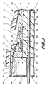
- Fig. 1 is a greatly enlarged partial view in elevation and longitudinal section along a central axis of a portion of a coaxial cable connector incorporating principles of the present invention.
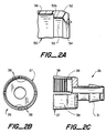
- Fig. 2A is a greatly enlarged diagrammatic view in elevation and longitudinal section of a portion of a resiliently elastomeric snap ring element of the Fig. 1 connector.
- Fig. 2B is an end view in elevation of the inside collet structure of the mandrel body of the Fig. 1 connector.
- Fig. 2C is a view in elevation and partial section of the mandrel body of the Fig. 1 connector modified to define an inside helical thread within the collet structure portion thereof.
- Fig. 2D is an end view in elevation of the inside collet structure in which the fingers thereof are formed by parallel saws.
- Fig. 2E is a view in elevation and partial section of the Fig. 2D mandrel body.
- Fig. 2F is a view in front elevation of an outer shell of the Fig. 1 connector.
- Fig. 2G is a view in partial section and side elevation of the Fig. 2F outer shell.
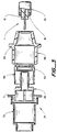
- Fig. 3 is a longitudinally exploded view of the Fig. 1 connector about to be installed on a prepared cable end of a coaxial cable with the aid of one form of expendable plastic assembly tool or jig.
- Fig. 4 shows the Fig. 3 assembly nested within the assembly jig incident to installation of the Fig. 1 connector onto the coaxial cable end.
- Fig. 5 shows the Fig. 4 assembly with the coaxial cable installed thereon.
- Fig. 6 shows the installed connector assembly with the outer shell element slid back to a position enabling the connector to be installed on a receptacle or jack.
- Fig. 7 shows the installed connector assembly mounted on a receptacle or jack with the outer shell pushed forward to lock the connector in place on the receptacle.
- Fig. 8A illustrates in front view and axial section a tined, resiliently elastomeric portion of a snap-ring in accordance with the principles of the present invention.
- Fig. 8B illustrates the Fig. 8A tined snap-ring in rear elevation.
- Fig. 9 shows in exploded view an alternative embodiment of connector in accordance with the principles of he present invention.
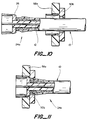
- Fig. 10 shows the Fig. 9 mandrel element positioned onto the prepared cable end.
- Fig. 11 shows the completed assembly of the Fig. 9 embodiment.
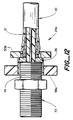
- Fig. 12 shows the Fig. 9 embodiment engaging a connection receptacle.
- Fig. 13 illustrates yet another embodiment of the present invention in unassembled, axially exploded view.
- Fig. 14 shows the Fig. 13 connector mandrel mounted on a prepared end of a coaxial cable.
- Fig. 15 shows completion of assembly of the Fig. 13 connector on the prepared end of the coaxial cable in accordance with the present invention.
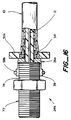
- Fig. 16 shows the Fig. 13 connector in engagement with a connection receptacle.
- Fig. 17 shows yet a further embodiment of the present invention inn unassembled, axially exploded view.
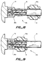
- Fig. 18 shows the Fig. 17 mandrel mounted on a prepared end of a coaxial cable.
- Fig. 19 shows completed assembly of the Fig. 17 mandrel on a prepared cable end and as mounted upon a mating connection receptacle.
- Fig. 20 shows another embodiment of the present invention in unassembled, axially exploded view.
- Fig. 21 shows partial assembly of the Fig. 20 mandrel being mounted on a prepared end of a coaxial cable.
- Fig. 22 shows placement of a resiliently elastomeric band over the Fig. 20 mandrel.
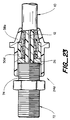
- Fig. 23 shows the now fully assembled Fig. 20 embodiment engaging a connection receptacle.
- Fig. 24 shows yet another embodiment of the present invention in unassembled, axially exploded view.
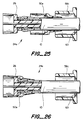
- Fig. 25 shows placement of the Fig. 24 mandrel onto the prepared end of a coaxial cable.
- Fig. 26 shows placement of a snap member over the mandrel-cable assembly depicted in Fig. 25.
- Fig. 27 shows the fully assembled Fig. 24 embodiment in electrical and mechanical attachment with a connection receptacle or jack.
- Fig. 28 illustrates yet another embodiment of a connector assembly in accordance with the present invention in unassembled, axially exploded view in elevation and partial section.
- Fig. 29 shows the Fig. 28 embodiment nested in initial, unassembled arrangement incident to installation upon a prepared coaxial cable end.
- An expendable insertion tool provides a nest or container for holding and aligning the uninstalled component parts of the Fig. 28 connector assembly in axial alignment to facilitate assembly onto the prepared end of the coaxial cable.
- Fig. 30 illustrates installation by rotation of the Fig. 28 container and nested connector assembly elements onto the prepared coaxial cable cable end.
- Fig. 31 illustrates the Fig. 28 connector assembly after the installation procedure of Fig. 30 has been completed.
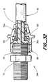
- Fig. 32 illustrates the assembled Fig. 28 connector assembly in electrical and mechanical connection with a receptacle or jack.
- Fig. 33 shows yet another embodiment of connector assembly in accordance with the principles of the present invention.
- Fig. 33 is an exploded view of the connector assembly in elevation and partial section along a longitudinal explosion axis.
- Fig. 34 illustrates the mounting of the mandrel portion of the Fig. 33 connector assembly onto the prepared cable end.
- Fig. 35 illustrates the Fig. 33 connector assembly following placement of a resiliently elastomeric band over the Fig. 33 mandrel.
- Fig. 36 illustrates the Fig. 33 connector assembly in electrical and mechanical attachment with a receptacle or jack.
- Fig. 37 comprises a cable end view in elevation of an embodiment of a colleting mandrel body which is radially expansive thereby to adapt and be used with coaxial cables having insulating cores of varying diameters within a predetermined range in accordance with principles of the present invention.
- Fig. 38 is a side view in elevation and section of the Fig. 37 mandrel body, taken along the line 38 in Fig. 37.
- Fig. 39 is a somewhat diagrammatic view in side elevation of the Fig. 38 mandrel body and an expendable conical, ramp-shaped colleting guide member enabling installation of the Fig. 38 mandrel body onto two cables having inner cores of differing diameters.
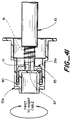
- Fig. 40 is a view in partial section and axial explosion of the Fig. 28 coaxial cable connector embodiment showing a modified container/nesting tool.
- Fig. 41 illustrates placement of the coaxial cable connector elements within the container tool and threading of the assembly and tool over the prepared end of the coaxial cable.
- Fig. 42 illustrates initial engagement of the dielectric core of the cable with the plug end of the container tool.
- Fig. 43 illustrates the final position of the Fig. 40 assembly when the dielectric core of the cable has pushed the container tool to a point of disengagement between the teeth thereof and the slots of the mandrel cap.
- a coaxial cable 10 includes a central longitudinal conductor 12 which is concentrically surrounded by a high dielectric, insulator material 14, such as plastic foam for example.
- a thin metal conductive foil or coating 16 typically formed of aluminum alloy, is bonded to the outer surface of and thereby contains the foam core 14 and embedded central conductor 12.
- An open mesh wire braid or wrap 18 is wrapped or placed immediately outside of the outer metal coating 16 to provide mechanical strength to the cable and yet, to permit the cable 10 to flex quite freely without damage. Additional layers of aluminum foil and wire braid may be included as part of a composite outer conductor. Together, these composite elements 16, 18 form an outer electrical conductor and shield which is substantially concentric with, and spaced (by the dielectric core material 14) away from the center conductor 12.
- An outer insulator coating 20 of a suitable thermoplastic resin material covers the outer electrical conductor to seal the cable from the ambient, to isolate the outer conductor electrically from the ambient and to provide some additional stiffness and mechanical protection to the cable 10.
- the cable 10 may be type RG-6 having a nominal overall diameter of about 0.70 mm (.275 inch), or a type RG-59 having a nominal overall diameter of about 0.67 mm (.240 inch).
- the diameter of the inner core material 14 of the RG-6 cable is about 0.47 mm (.185 inch), whereas the diameter of the inner core material 14 of the RG-59 cable is about 0.37 mm (.145 inch), thereby illustrating a core diameter variance range of about 0.1 mm (.040 inch) between two very popular indoor cables.
- the end of the cable 10 has been prepared by cutting back the outer conductor 20, outer braid 18, outer foil jacket 16 and dielectric core 14 for a short distance to a location referred to by the lead line associated with the reference numeral 22 in Fig. 1, so as to expose a short segment of the central conductor 12.
- the exposed segment of the central conductor 12 is engaged by a central conductor receptacle within a conventional jack typically having a threaded outer cylindrical surface.
- the jack may be a standard threaded "F" port connector having a nominal outer diameter of about 0.95 mm (.375 inches) although this diameter is known to vary somewhat in practice.
- a preferred embodiment 24 of a connector incorporating the principles of the present invention includes a mandrel body 26 formed of a suitable conductive material, such as yellow brass, for example.
- the mandrel body 26 is die cast with a two-part mold that separates along the longitudinal axis of the mandrel body 26.
- the mandrel body 26 is formed with suitable reliefs and edge contours, so that it cooperates as intended with the other structural elements of the connector without scratching or unwanted interferences.
- eac mandrel body 26 may be formed in less than one second, leading to substantial economies in manufacturing.
- the mandrel body 26 is plated with a suitable metal or alloy, such as tin, in order to improve its lubricity characteristics.
- the conductive mandrel body 26 includes a thinned tubular region 28 with a slight, axially converging chamfer 29 at the end of the body 26.
- a frustoconical region 30 forms a frustoconical outer surface region 31.
- the frustoconical outer surface region 31 forms an acute angle (less than 90 degrees) with a central longiudinal axis of the mandrel body 24 (which is generally in alignment with the central conductor 12 of the coaxial cable 10).
- the angle formed by the surface region 31 with the longitudinal axis is between about 20 degrees and about 5 degrees, and it is preferably 10 degrees, plus or minus one degree.
- a first, radially extending annular wall 32 extends outwardly to converge the inner end of the frustoconical surface 31 thereby to form an annular knife-edge projection or barb 33.
- the barb edge 33 is designed to be a cutting surface which cuts or bites slightly into an inside ring portion of the outer metal braid and foil layers 18 without actually shearing them, thereby to cut through any oxide or other insulating formations or deposits on the inside surface of the metal foil 16 so as to achieve and maintain a positive, very low resistance electrical connection between the mandrel body 26 and the outer conductor foil and braid 18.
- the frustoconical surface 31 forms an acute angle with the annular wall 32, most preferably about 30 degrees
- a thinned tubular region 34 extends away from the base of the first radial wall portion 32 and meets a thickened second radial wall portion 36.
- the second wall portion 36 extends radially outwardly to the location of a collet structure 37 at which fingers or leaves 38 extend.
- the fingers 38 define the inside collet structure 37 and provide an inside cylindrical engagement surface suitable for engaging the outer threaded surface of a jack with which the connector 10 is intended for use, such as an "F" jack, for example.
- the inside surface of the collet structure 37 may be smooth, as shown in Fig. 1, or it may be provided with a shallow-cut helical groove or thread 39 as shown in Fig. 2C.
- a radially diverging chamfer or bevel edge 40 at the entrance of the collet structure of fingers 38 facilitates slidable engagement of the leaves or fingers 38 upon the threaded surface of the jack.
- the pitch of the groove 39 is set to correspond with the thread pitch of the jack. If the groove 39 is present, a more positive attachment is achieved with the threaded jack than if the thread 39 is not provided, should such a characteristic be desired.
- each finger 38 is formed with a thickened region 42 adjacent to the chamfer 40 and becomes gradually thinned at a region 44 adjacent to the second, thickened radial wall portion 36.
- the inside geometry of the connector 24 is generally cylindrical when in an unstressed, uncompressed state. In this relaxed state which enables the conductor 24 to be slid over the outer surface of the jack, the outer surfaces of the fingers 38 define a slightly curved or frustoconical geometry.
- fingers 38 there may be more or fewer fingers; however, four fingers 38, each defining a quadrant of a cylinder and separated by longitudinal slots 46 from adjacent fingers, cooperate to provide a very effective compression collet closure structure for positive engagement over the outer surface of the jack, when a hoop, band, slip ring, or other circumferentially compressing member is slidably positioned over the thickened regions 42 of the fingers 38.
- the fingers 38 may be formed by cross-sawing across the collet structure 37 at right angles, as shown in Fig. 2B, for example.
- the fingers 38 are formed by a single machining operation of two parallel saws which move in one direction across the collet structure 37, as shown in Figs. 2D and 2E.
- the connector 24 further includes a resiliently deformable elastomeric cap 50 which is preferably formed by injection molding of a suitable thermoplastic resin material.
- the cap 50 includes a deformable flange region 52 which becomes thinned and tapered into a rearwardly flaired, knife-like annular edge 54.
- a cap region 56 snugly fits over the fingers 38 and provides some additional hoop strength and protection to the fingers 38 from overbending due to proper insertion into the jack.
- the cap 50 is dimensioned such that the flange region 52 snap-locks into a recess formed adjacent to the first radial wall 32 of the mandrel body 26. Since the flange region 52 is initially flaired outwardly, the thinned annular edge 54 curls up around the outer plastic insulation 20 and tends to stretch or pull it down over the knife edge 33 of the mandrel body 26. When positioned against the outer insulator 20 of the cable 10, the flaired edge 54 of the cap 50 actually presses the cable 10 against the first radial wall portion 32, causing the outer conductor braid and foil layers 18 to become sharply creased at the knife edge 33.
- an outer shell 58 is provided which further cooperates with and strengthens the connector 24.
- the shell is formed by injection molding of a hard plastic material, such as 6/6 nylon.
- the shell 58 has a forward cylindrical portion 60 which is dimensioned to compress the mandrel fingers 38 against the outer surface of the jack when the portion 60 is slid forward along an axial locus denoted by the arrow 61.
- An inside edge region 62 of the portion 60 bears against the cap region 56 which in turn presses inwardly against and compresses the fingers 38 toward the outer surface of the jack in the manner of a compression collet.
- a rear, frustoconical portion 64 of the shell 58 positions an inside surface 66 against a region of the outer plastic insulator 20 adjacent to the frustoconical surface 31 of the mandrel body 26.
- the inside surface 66 thereby clamps the insulator and outer conductor jacket against the surface 31, thereby preventing relative movement of the cable 10 relative to the connector 24 and particularly relative to the knife edge 33, and further accentuating the creasing action of the outer conductor jacket over the mandrel knife edge 33 and preventing rearward movement relative to the connector 24.
- the outer shell 58 must have a sufficiently high modulus of elasticity and resilience to stretching so that it effectively closes the fingers 38 of the collet structure 37 as the shell 58 slides forward over the mandrel body 26. Since "F" jacks are found in practice to range in diameter over about an 0.04 mm (.15 ⁇ ) range, the sizing of the inside diameter of the edge region 62 should be such that when the front edge of the outer shell portion 60 is slid about halfway over the collet structure 37, a secure grip is thereby achieved between the structure 37 and a jack of nominal diameter, e.g. 0.95 mm (.375 inches).
- jacks of the "F" type may be securely engaged by the connector 24, particularly if the inside surface of the collet structure 37 is provided with the shallow thread 39, as shown in Fig. 2C.
- a modulus of elasticity of at least 689 MN/m2 (100,000 pounds per square inch), and a resiliency enabling stretching up to about four percent of nominal are presently preferred characteristics for the outer shell 58.
- An oxide-formation preventing gel may be coated onto the mandrel body 26 on the radial wall portion 32 adjacent to the knife-edge 33, or on the frustoconical surface 31, or at both locations as desired.
- the gel may have lubricating properties and may facilitate insertion of the mandrel body 26 between the dielectric core 14 and the outer conductor foil jacket 16.
- Gels under compression such as disclosed in commonly assigned U.S. Patents Nos. 4,634,207; 4,643,924; 4,721,832; and, 4,701,574, the disclosures of which are hereby incorporated by reference, are suitable for use with the embodiments of the present invention disclosed herein.
- a space 53 is provided between the thickened radial portion 36 of the mandrel body 26 and the flaired region 52 of the deformable elastomeric cap 58. This space 53 enables excess outer cable material to be curled up and accomodated, further relaxing the tolerance requirements for preparation of the end of the cable 10 for installation of the conductor 24.
- a molded plastic assembly tool or jig 70 is shown in axial alignment with the other components previously discussed in conjunction with Figs. 1 and 2.
- a molded plastic assembly tool or jig 70 is shown in axial alignment with the other components previously discussed in conjunction with Figs. 1 and 2.
- an end 11 of the cable 10 is prepared as shown, so that the foam core 14 and exposed outer coating 16 extend a small distance beyond the outer insulator 20, and braid and aluminum foil layers 18.
- the braid and foil layers 18 are folded up and radially outwardly away from the longitudinal axis of the cable 10.
- the cable end 11 may be prepared with a special tool, or simply by using a sharp knife or single edge razor blade.
- the stubby wires of the braid and foil layers 18 are folded back by the installer's finger after the ring of outer insulator coating has been cut away.
- the mandrel body 26, cap 50 and outer shell 58 are nested into the assembly tool 70 in preparation for receiving the prepared cable end 11 as shown therein.
- a annular ring portion 71 of the tool 70 provides a convenient grip location for the user's fingers.
- the cable is gripped in one hand, and the assembly tool 70 containing the body 26, cap 50 and outer shell 58 is gripped in the other hand. Then, the cable is pushed toward the tool 70 and into and through the the outer shell and cap 50.
- the cable engages the mandrel body 26, it pushes the body forward and away from the cap 50 and outer shell 58, as shown in Fig. 5.
- the cable end 11 is shown inserted into the tool 70 and the end has pushed the mandrel body 26 to the forward end of the tool 70, passing over and leaving behind the cap 50 and the shell 58.
- the tool 70 is formed of a transparent plastic material, then it is possible for the installer to see that the cable end 11 has passed over the frustoconical region 30 and the thinned tubular region 34 and is butted up against the outside of the second radial wall portion 36. In this manner the transparent tool 70 acts as a gage for aiding proper installation.
- the cable 10 is then pulled away from the tool 70, with the installer grasping the outer shell 58.
- the outer shell 58 retains the cap 50 and causes it to slip over the cable 10 and over the annular bulge therein now formed by the outer jacket elements lying upon the surface 31.
- the cap 50 Continuing to pull the cable 10 relative to the shell 58 causes the cap 50 to be moved into its final locking position over the thinned tubular region 34 in front of the first wall portion 33, as shown in Fig. 1.
- the cap 50 is thus snap-locked against the outer insulator 20 at the vicinity of the radial wall 32 and prevents rearward movement of the cable 10 by coaction with the knife edge barb 33 of the mandrel body 26.
- the tool or jig 70 forms a convenient package for containing a kit of parts including the mandrel body 26, snap-lock cap 50 and outer shell 58.
- a "blister-pack" package may include the tool and parts and be formed onto a cardboard substrate for convenient distribution to the householder or other installer/user of the connector 24.
- the substrate may conveniently provide printed instructions and illustrations for assembly and use of the connector 24.
- the connector assembly 24 has been withdrawn from the tool 70 (which may now be discarded as spent, or retained for installation of another connector' assembly 24). Then, with the outer shell in the slid back position as shown in Fig. 6, the connector 24 may be pushed onto a jack 72, as shown in Fig. 7.
- the exemplary jack 72 typically an "F" jack, may define an outer threaded surface 74 against which the fingers 38 of the mandrel body 26 come into contact.
- the shallow thread 39 (if present on the inside surface of the collet structure 37) is pitched to mate with the threaded surface of the jack.
- the outer shell 58 is then slid forward to a position shown in Fig.
- the outer shell 58 may be grasped between the fingers and rotated to facilitate loostening the connector from the jack. The shell 58 is then slid rearwardly, thereby releasing the fingers 38 and enabling ready removal of the connector assembly 24.
- An outer annular ring or a pair of opposed flanges 59 (Figs. 2F and 2G) formed on the shell 58 provides a suitable thumb-finger gripping mechanism to enable rotatable and slideable movement of the shell 58 relative to the mandrel 26, cap 50 and cable 10 for installation and removal of the connector 24 to and from the jack 72.
- Fig. 8 shows a cap 50a which is provided with a plurality of splines 55 in lieu of the continuous resilient portion 54.
- the operation of the cap 50a is similar with that described for the cap 50.
- the splines 55 dig into the outer plastic insulation 20 of the cable 10 to create a series of stress points or barbs which coact securely to retain and lock the braid and foil layers 18 against the knife- edge barb 33.
- the pointed tips of the splines 55 actually dig into the outer plastic coating 20.
- FIGs. 9-12 illustrate an alternative embodiment 24a of a connector embodying the principles of the present invention.
- a modified cap 50b includes a thickened radial portion 52a leading to the deformable annular edge 54.
- a disk 58a provides the finger closure function provided by the region 60 of the shell 58, previously described.
- the advantage of this embodiment 24a is that it provides a very flat and compact connector assembly. Also, there is very little drawback from stress relaxation of the thick disk, a problem sometimes encountered with the thinner outer shell 58 of the earlier described embodiments.
- One disadvantage with the connector 24a is that without the portion 64 of the outer shell, there is no additional reinforcement or support provided to the cable end at the vicinity of the frustoconical portion 30 of the mandrel body 26.
- Figs. 13-16 illustrate yet another embodiment 24b of connector embodying the principles of the present invention.
- the outer shell 58 has been replaced by a split ring 58b which is nested in a suitable band retention structure 39 formed around the periphery of the fingers 38 of the mandrel shell 26a.
- the cap is formed as a disk 50c which includes the elastomeric edge 54.
- An outer portion of the disk 50c enables the fingers to grasp the connector 24b for installation and removal from the jack 72. Because of the thickness of the disk 50c, there is very little stress relaxation, and once installed on the cable end over the mandrel body, the disk 50c will securely lock the cable end to the mandrel body 26.
- This embodiment 24b also has the drawback of not providing any structure for retaining the cable at the frustoconical portion of the mandrel body as is provided by the outer shell 58. Also, the split-ring 58b does not provide as secure an engagement with the jack as is achieved with the inside compression collet structure 37.
- Figs. 17-19 illustrate a connector 24c also embodying the principles of the present invention.
- a connector 24c also embodying the principles of the present invention.
- only two elements are present, a slightly modified mandrel body 26b, and an elongated elastomeric threaded cap 50c.
- the fingers 38 of the mandrel body 26b are thickened for greater hoop strength.
- the threaded cap 50c is fit over the cable 10.
- the cable end 11 is then installed on the mandrel body 26b, and the cap 50c is then threaded onto the mandrel-cable arrangement as shown in Fig. 19, thereby securing the cable end 11 to the mandrel body 26b.
- Figs. 20-23 illustrate yet another embodiment 24d embodying the principles of the present invention.
- the cap 50 is replaced by a cylinder 50d of elastomeric material.
- the cylinder 50d and an outer shell 58b are positioned onto the cable 10, and it is then forced onto the mandrel body 26 as with the connector 24.
- the shell 58b is then used to push the elastomeric cylinder 50d into a position overlying the knife edge 33 of the mandrel body 26, as shown in Fig. 22.
- the connector 24d may be installed on the jack 72 and the shell 58b slid forward to lock the fingers 38 onto the outer threaded surface 74 of the jack, as shown in Fig. 23.
- the connector 24e shown in Figs. 24-27 reveals yet another combination of cap 50e and outer shell 58c for use with the originally described mandrel body 26.
- the cap 50e includes an elongated tail section 53 which is dimensioned and configured to overly the knife edge 33 of the mandrel body 26.
- the outer shell 58 When assembled and installed on the jack 72, the outer shell 58 is pushed to its forward position by grasping the outer flange 59. This action locks the fingers 38 onto the threaded outer surface 74 of the jack 72.
- a tapered annular edge 63 cooperates with the cap 50e to provide further compression to the cable jacket at the vicinity of the knife edge 33, as shown in Fig. 27.
- the connector 24f shown in Figs. 28-32, includes a mandrel body 26c in which the frustoconical knife-blade edge 33 of the prior embodiments is replaced by a knife-blade helical thread or edge 33a projecting radially outwardly from the thinned tubular region 28.
- the thinned tubular region may be slightly frustoconical and have an average outside diameter of about .180 inch.
- the helical knife blade edge 33a has an apex which is approximately 0.46 mm (.210 inch) and is formed as an acutely angled projection extending from the tubular region 28.
- the helical knife blade 33a is so shaped as to bite sufficiently into the fine aluminum strands of the outer conductor braid or aluminum foil to obtain a positive electrical contact with the foil and also to provide a positive mechanical securement therewith, without causing the strands to shear or break off.
- Knitoothness of the knife edge is to make it flat across for about two to three mils.
- a 0.025 mm (one mil) flat is too sharp and will result in shearing the fine wire braid, while an 0.2 mm (eight mil) radius at the edge has been found to be too dull with resultant slippage of the braid under tension.
- the knife blade 33a should subject the braid wires to shear stresses without actually resulting in shearing them off. In practice the compromise is reached by considering sharpness of the knife edge 33a and the hardness of the material of which it is made.
- the jig or tool 70a is modified to include teeth 80 which are sized and positioned to engage the slots 82 defined between the fingers 38 of the collet structure 37.
- An outer end portion 84 of the tool 70 may be provided with radial spokes or projections to facilitate gripping and impartation of rotational torque to the tool 70 to enable insertion of the threading mandrel 26c onto the prepared end of the cable 10. Rotational installation of the mandrel 26c onto the prepared cable end is illustrated diagrammatically in Fig. 30 by the arrow 84.
- a helical knife-blade edge 33a on the mandrel 26c has been found to be particularly advantageous in order to facilitate ready installation of the assembly 24f onto the coaxial cable 10 at low ambient temperatures which cause substantial stiffness of the outer elastomer jacket 20 thereof.
- the outer jacket 20 has stiffened due to lower ambient temperatures, it aids in causing the helical knife-blade edge 33a to bite into and positively engage the outer conductor braid/foil of the coaxial cable 10.
- the assembly of the connector assembly 24f is the same as described hereinabove for the assemby 24.
- the connector 24g shown in Figs. 33-36, combines the Fig. 28 helically threaded mandrel body 26c with the elastomeric cylinder 50d used in the Fig. 20 connector embodiment 24d.
- the mandrel 26c is threaded onto the prepared cable end as explained above in connection with the connector body 24f of Fig. 28, whereas the elastomeric cylinder 50d is positioned as explained in conjunction with the Fig. 20 embodiment above.
- the mandrel body 26d solves a problem otherwise associated with coaxial cables having different diameter foam cores within a predetermined size range.
- an RG-59 cable 10a may have a diameter of about 0.37 mm (.145 inch) for the core 16a
- an RG-6 cable 10b may have a diameter of about 0.47 mm (.185 inch) for its core 16b.
- Both cables may be effectively terminated by a connector assembly including the mandrel body 26d.
- the body 26d, otherwise identical to the body 26, is formed to define e.g. four longitudinal slots 86.
- the slots 86 are very narrow, e.g.
- An inside diameter, denoted by reference numeral 88, at the cable end corresponds generally to the outside diameter of the smallest cable core 16a within the size range to be accomodated, while an inside diameter, denoted by reference numeral 90, of the central bore of the tubular portion 34 of the mandrel body 26d is sized to accomodate the outside diameter of the largest cable core 16b within the predetermined size range.
- the frustoconical portion 30a of the mandrel body 26d is tapered toward the cable end diameter 88 on both the inside and outside thereof.
- An expendable ramping tool 92 is provided for use in attaching the mandrel body 26d to the prepared cable end.
- the ramping tool 92 when positioned axially over the exposed central conductor 12 of the cable 10 to abut the core 16 causes the fingers formed by the slots 86 to expand radially as the mandrel body 26d is pushed toward the core 16. This radial expansion of the cable end of the mandrel body 26d positions it so that it will properly come into overlying engagement with the cable core, whether it be of a smaller diameter such as the core 16a, or of a larger diameter such as the core 16b. After the outside of the core 16 is engaged, the ramping tool is forced axially all the way through the tubular portion and into the region enclosed by the collet structure 37 where it may be readily removed and discarded by the installer.
- frustoconical knife-blade edge 33 is illustrated in the Fig. 37-39 embodiment, it is clear that a helical knife blade edge 33a may also be used with equally successful results in this embodiment.
- a modified tool 70b illustrated in combination with the elements of the connector 24f and the cable 10.
- the tool 70b has a significant advantage in that it automatically prevents over-installation of the connector mandrel 26c onto the prepared cable end.
- the tool 70b is configured to prevent the mandrel body 26c from being rotated too far onto the prepared cable end.
- the tool 70 is formed with a hollow cylindrical plug region 83.
- the plug region 83 is concentric with the connector elements and with the prepared cable end.
- the plug region 83 defines an inner wall 85 which butts up against the mandrel body, as shown in Fig. 41.
- a central opening 87 is defined through the inner wall 85. Since the center conductor wire 12 has a diameter which typically ranges between 0.81 mm (32 mils) and 1 mm (40 mils), the central opening 87 is sized to be about twice the largest wire diameter, or about 2 mm (80 mils) in diameter.
- This diameter is selected for two very important reasons: first, it is sufficiently smaller than the diameter of the dielectric core 16 of the cable 10 so that an end wall 17 thereof will come into contact with the inner wall 85 and thereafter dislodge the tool 70b. Secondly, the small diameter opening 87 serves as a gage to be sure that the center conductor 12 which is exposed at the prepared cable end is not bent. (If the exposed end of the inner conductor 12 is bent, damage will likely ensue to the center contact within a receptacle with which the assembed conductor and cable end will be used).
- Fig. 41 illustrates a position at which the mandrel body 26c has been screwed onto the prepared end of the cable 10 to a position at which the endwall 17 of the dielectric has butted up against the inner wall 85 of the tool.
- the installer may rotate it relative to the cable 10 until automatic disengagement occurs, at which point the mandrel body 26c is properly installed to a correct length along the prepared cable end. While the same concept may be employed with a push-on tool 70 and annular barb 33, discussed previously, it is particularly advantageous to use the concept with the mandrel body 26c having the helical thread barb 33a.
- the present invention realizes a three-part feedthrough connector assembly for a coaxial cable which may be readily installed upon a prepared end of a coaxial cable, and which efficiently and effectively clamps onto the prepared cable end to provide a secure electrical and mechanical securement to the outer conductor.
- a locking mechanism for locking the connector onto a jack or receptacle, and an installation tool, provide important aspects of the present invention.
- the outwardly diverging shape of the inside compression collet 37 may be curved as opposed to frustoconical thereby to enable. overstroke to account for the range in diametral tolerances of various jacks within a type with which the connector may be used.
- the outwardly divergent shape may be provided by the cap member 50.
Landscapes
- Coupling Device And Connection With Printed Circuit (AREA)
- Communication Cables (AREA)
- Insulated Conductors (AREA)
- Multi-Conductor Connections (AREA)
Abstract
Description
- The present invention relates to connectors for coaxial cables. More particularly, the present invention relates to a very low cost, easily installable feedthrough connector for coaxial cable of the type typically used indoors for wideband RF signal distribution, for example.
- Coaxial cable is in widespread use for distributing wideband radio frequency ("RF") information, such as television and radio signals. Coaxial cable typically provides two conductors, a central axial conductor and an outer conductor which is substantially concentric with the inner central conductor. The central conductor is typically completely surrounded by the outer conductor, and a low-loss, high dielectric insulation material, such as plastic foam, separates the two conductors. An outer insulating jacket is usually, although not necessarily, provided over the outer conductor to provide electrical insulation and physical protection to the cable. The outer conductor may be a single element, or it may be a composite of several layered elements of conductive foil, wire braid, etc. One element of a composite outer conductor construction may be a conductive film or coating applied to the outside surface of the low-loss, high dielectric insulation material.
- Relatively large diameter, semi-rigid coaxial cables are widely used outdoors in cable television distribution networks as a delivery conduit for delivering the cable network signals to drop box locations near the service subscriber's premises. Smaller, more flexible coaxial cables having external insulating jackets are used to provide service drops to the subscriber premises.
- Connectors are provided for connecting the cables in the outdoor environment. Such connectors not only must provide positive, signal-tight electrical connections, they must also provide positive leak-tight, sealed physical connections to prevent intrusion of moisture into the cable. Installation of such connectors typically requires cable end preparation such as coring or removal of the insulator dielectric core for some distance, followed by installation and tightening of the conductor assembly by a trained craftsperson, with or without special tools, depending upon the conductor/cable design. Typically, the outdoor environment connectors provide a central connector element which is secured in coaxial arrangement over an exposed end portion of the central conductor. The central connector element thus contributes significantly to the securement of the connector structure to the prepared cable end.
- Usually, the distribution network operator does not want a subscriber to install a connector to a cable for use with "outside plant" distribution boxes, cables and the like; thus, special keyed tools are often provided for use by trained installers in order to preclude unauthorized access to system distribution boxes, service drops and the like.
- Within the subscriber premises the opposite situation often exists. Usually, the subscriber has a number of appliances which require interconnection and connection to the service cable outlet jack, typically mounted to and extending outwardly from a wall plate within the home or other interior location, etc. Connections may be needed between the service jack and the jacks of a television set, a video cassette recorder ("VCR"), and a stereo FM receiver, for example.
- Small diameter (approximately one quarter inch or smaller), flexible coaxial cables are typically employed to accomplish the needed connections. These coaxial cables typically include a solid wire central conductor, a foam core, an outer composite conductor formed of an inner aluminum coating on the foam core, one or more layers of open-mesh aluminum wire braid and one or more layers of an aluminum foil. The outer composite conductor is typically covered by a plastic outer insulator jacket of one or several layers of insulating material in order to complete the coaxial cable construction. The dimensions of such coaxial cables may vary, depending upon type and source thereof. Also, the properties of the cable may vary, depending on type and source, and also depending upon such factors as ambient temperature. When ambient temperature is low, the polymer cable materials become very stiff and difficult to manouver during connector installation procedures. Also, the foil coated inner insulating core may vary in diameter from about .140 inch to as much as about .200 inch.
- These small diameter cables have been made available to the consumer in standard lengths with connectors installed at the factory. Also, connectors have been made available for installation, but installation of these connectors to a prepared cable end has typically required a crimping tool for crimping a retaining ferrule, or a tool for spreading a retaining slip ring, or the tighening of a compression nut which retains the connector to the cable end, or the like. Some connectors for indoor service provide and require compressive coaction between the face of the threaded jack and the connector body, which is achieved in practice by tightening a threaded nut of the connector over the outer threads of the jack.
- The connectors for indoor service are known as "feedthrough" connectors, in the sense that there is no separate central connector element of the connector provided for connection, the center conductor of the cable providing this element of the connection mechanism. The center conductor is usually engaged by a receptacle element of a jack. Such element, sometimes referred to as a center seizure mechanism, when present, provides a positive mechanical engagement between the connector assembly and the center conductor of the coaxial cable.
- In the case of the feedthrough connector, an exposed end portion of the solid wire central conductor of the coaxial cable is directly engaged by the center seizure mechanism of the jack when the feedthrough connector is mounted thereon. Since the central conductor of the coaxial cable is not maintained in mechanical engagement with the feedthrough connectors, and since those connectors function only to feed or connect the outer conductor to the jack and thereby to position the exposed central conductor for engagement with the central gripping mechanism of the jack, the prior techniques for securing the connector to the cable have proven to have drawbacks related to installation and have proven not to be entirely satisfactory for ready installation and extended, reliable use within indoor use environments.
- Irrespective of the particular approach followed by the prior art, hitherto there has not been a very low cost feedthrough coaxial cable connector which may be easily assembled and attached to the cable with a simple manipulation by a user without special tools, or skills, and which provides a positive, superior engagement over time with the jack to which it is mated for use.
- A wide variety of techniques are to be found in the coaxial cable connector art for attaching a feedthrough connector to a prepared cable end. One representative example is to be found in the Quackenbush U.S. Patent No. 3,781,762. Therein, a tubular connector body includes an annular flare. The body is dimensioned to fit between the insulating core and outer conductor of the prepared cable end, and it aligns and positions an exposed end section of the central conductor. The annular flare of the tubular body causes the outer conductor to become stretched over it as the body is pushed between the core and the outer conductor during installation. A cylindrical ferrule, such as a split ring or crimp ring, is then installed over the body inside of the annular flare. The Quackenbush arrangement is said to provide good electrical and mechanical connection of the cable outer conductor to the connector body. However, the Quackenbush connector cannot be easily installed on the prepared cable end without special tools needed for installation of the clamping ferrule.
- As mentioned, another feedthrough connector relies upon a compression engagement obtained by tightening a threaded nut to the jack. The tightened nut of the connector compresses the outer conductor against the connector body and thereby secures the connector to the cable. One drawback of this approach is that when the nut is not tightened upon the threaded jack, or when the connector end is not engaged with the jack, a slight tug or jerk on the connector may cause it undesirably to become separated from the cable.
- Other more conventional approaches are to be found in the coaxial cable connector art which include means for engaging the exposed end of the central conductor. For example, British Patent Specification 621,459 describes a tubular connector body for insertion between the insulation core and the outer conductor of a coaxial cable. An annular flared or bulged region expands the outer conductor of the cable, and a longitudinally extending split ferrule tube is pushed over the coaxial cable end to surround the body at the bulged region so as to press the cable against the bulged region to improve electrical connection and mechanical attachment. The ferrule includes fingers enabling it to be secured to the connector body after it is positioned in place.
- An annular split ring is described in the Leeper U.S. Patent No. 2,805,399 in order to retain an outer conductor of a coaxial cable along a narrow ring location immediately adjacent a bulged annular frustoconical clip portion of a body which is slipped under the outer conductor of the coaxial cable in order to provide very secure mechanical retention of the cable to the connector. Here, a special tool is needed in order to position and install the slip ring.
- In the Pugner U.S. Patent No. 4,053,200, a connector body has two radially raised portions. A plural-fingered, elongated brass ferrule slides over the cable and the outer radially raised portion in order to seat or nest between the two raised portions of the body and press the outer conductor of the cable against the connector body. While the elongated brass ferrule provides a radial band of circumferential compression force to press the cable outer conductor against the tubular body, similar to the manner described in the Quackenbush reference discussed above, no engagement is provided between the elongated ferrule or other structure of the connector and the cable behind the outer raised portion of the connector body. Apparently, to aid requisite securement of the cable to the connector, the Pugner reference teaches a central connector structure which is crimped or otherwise secured to an exposed end section of the central conductor of the cable.
- Without the further retention means by the central connector structure as shown in the Pugner patent, tugging and pulling stresses upon the coaxial cable will tend to cause it to become disconnected from the connector as described by Pugner, especially if the connector is threaded onto the jack at the time. Also, any flexures of the cable, particularly within an indoor environment such as the home, will tend to cause the outer conductor to stretch and possibly to lose effective electrical contact with the ridge of the outer raised portion and/or provide an unwanted signal leakage path at the connector.
- The Schwartz U.S. Patent No. 3,264,602 provides a connector body for a coaxial cable which has a rearwardly tapered, ringed frustoconical surface which is slipped under the outer conductor of the coaxial cable. An outer member snap-locks over the cable in a manner which compresses the outer conductor against the frustoconical surface in order to lock the cable to the connector and to provide a positive electrical connection between the inner surface of the outside conductor of the cable and the facing frustoconical ringed surface of the conductive connector body.
- The Lee U.S, Patent No. 4,789,355 provides a coaxial cable connector plug which has tines or leaves which slide over the threaded end of the jack. An outer annular sleeve may then be pushed forward over the tines in order to compress them against the threaded jack and lock the connector plug against the jack in the manner of a compression collet, even though the plug is not threaded to mate with the threads of the jack.
- The Samichisen U.S. Patent No. 4,834,675 describes what the inventor calls a "snap-n-seal" coaxial cable connector for a prepared end of a coaxial cable. This four-part connector assembly includes a
mandrel body 30 which has a rampedcontour 39 diverging from the rear end thereof, so that thebody 30 may be press fit between the dielectric core and the shielding braid. As seen in Fig. 2B and as best seen in Fig. 4, the rampedcontour 39 appears to flatten out and ends at a step inwardly forming a right angle with the flattened region. Aplastic compression sleeve 60 is pushed over thebody 30 and the cable end. The compression sleeve snap-locks into ametal collar member 20 and is said thereby to lock the cable end to the connector assembly. Since the rampedcontour 39 appears to end at a flattened region, thebody 30 fails to provide a knife edge for effectively cutting into the braid or aluminum sheet forming the outer conductor of the coaxial cable. There is no elastomeric compression member. - The Ito et al. U.S. Patent No. 4,249,790 describes a push-on type connector plug for a coaxial cable end. In pertinent part, the connector plug includes a slotted shield casing forming a plurality of resilient fingers which engage the outer cylindrical surface of a connector receptacle as the connector plug is pushed onto the receptacle. The fingers appear to be contoured to cooperate with an outer band structure in order to provide a spring bias force which pushes the fingers against the outer cylindrical surface of the receptacle and thereby provide a good electrical and mechanical push-on, pull-off attachment.
- The Morello Jr. U.S. Patent No. 3,196,382 describes a crimp type
coaxial cable connector 12 which includes a mandrel body having an integrally threaded mating cap for mating with areceptor connector 14. The Morello Jr. connector device is not a push-on feedthrough connector. - While the foregoing approaches recognize the problem of providing effective contact and positive mechanical attachment of the prepared cable end and the cable connector, none of the foregoing approaches achieve a simplified, easily installed, positively acting feedthrough coaxial cable connector intended primarily for ready installation by the untrained user or consumer or by the trained technician, and for reliable use typically within an indoor environment over an extended time period.
- A general object of the present invention is to provide a feedthrough coaxial cable connector which overcomes the limitations and drawbacks of the prior art.
- A more specific object of the present invention is to provide a feedthrough coaxial cable connector for indoor use which may be installed by a user with exertion of but moderate finger strength and without any special tools or skills being required.
- One more specific object of the present invention is to provide a feedthrough coaxial cable connector which achieves improved flexual strain relief against rearward pulling force thereby to prevent the cable from being disconnected from the connector in response to tugging or pulling forces whether or not the connector is pulled free of the jack. That is to say, a specific object of the present invention is to provide a feedthrough coaxial cable connector which preferentially releases from a jack with which it is mated, rather than becoming damaged and inoperative by separation of the connector and the coaxial cable end.
- Yet another specific object of the present invention is to provide a kit of a few co-acting parts which may be assembled and installed by the consumer as a connector on an easily prepared end of an indoor coaxial cable by hand without special tools and without special training or skills.
- According to one aspect of the present invention a feedthrough coaxial cable connector for connecting to a prepared end of a coaxial cable having an exposed solid-wire central conductor, the connector comprises:
a tubular mandrel body (26) of conductive material dimensioned to be pressed between a dielectric core (14) and an outer conductor (18) of the prepared end of the cable, the mandrel body (26) including a cable engagement surface portion (30) defining a projecting edge (33) extending therearound for engaging outer conductor (18) of the coaxial cable, a tubular shank portion (34) extending from the cable engagement surface portion (30) to a radial wall portion (36), and a receptacle engagement portion (37) coaxially extending forwardly from the radial wall portion (36) and coaxially disposed about the exposed central conductor (12) and dimensioned to slide onto and contact in close fitting friction engagement an outer surface (74) of a receptacle means (72) with which the connector mates in use, and radial compression means (50) for compressing the inside surface of the outer conductor (18) of the coaxial cable over the edge (33) of the cable engagement surface of the mandrel body (26) in order to place the outer conductor (18) into shear stress and without shearing the outer conductor, characterized in that the compression means comprising a retention ring (50) having a resiliently deformable portion (52) of elastomeric material which coacts with the tubular shank portion (34) and an annular (33) or helical (33a) blade of the projecting edge (33) forming an annular or helical barb of the mandrel body such that, once locked in place, the resiliently deformable portion of the retention ring (50) effectively locks the cable on to the connector, - According to a further aspect of the present invention provides a kit of parts for assembly into a feedthrough coaxial cable connector at a prepared end of a coaxial cable having an exposed solid-wire central conductor, the unassembled kit of parts comprising:
a tubular mandrel body (26) of conductive material dimensioned to be pressed between a dielectric core (14) and an outer conductor (18) of the prepared end of the cable, the mandrel body (26) including a cable engagement surface portion (30) defining a projecting edge (33) extending therearound, a tubular shank portion (34) extending from the cable engagement surface portion to a radial wall portion (36), and a jack engagement portion (37) and coaxially disposed about the exposed central conductor (12) and dimensioned to slide onto and contact in close fitting friction engagement an outer surface (74) of a jack with which the connector mates in use, and
radial compression means for compressing the inside surface of the outer conductor of the coaxial cable over the edge (33) of the tubular mandrel body, the compression means comprising a retention ring (50) having a resiliently deformable portion (52) of elastomeric material which coacts with the tubular shank portion (34) and an annular (33) or helical (33a) blade of the projecting edge (33) forming an annular or helical barb of the mandrel body such that once locked in place, the resiliently deformable portion of the retention ring (50) effectively locks the cable on to the connector, - According to a still further aspect of the present invention there is provided a method for assembling a feedthrough coaxial cable connector from a kit of parts at an end of a coaxial cable, the method comprising the steps of:
preparing an end of the cable (10) by peeling back a first cylindrical portion of an outer insulator covering (20) for a first length to expose an outer conductor braid/foil layer (18), and peeling back the outer conductor braid/foil layer and coaxially underlying dielectric insulator (14) for a second length shorter than the first length thereby to expose a center solid conductor wire (12) end portion,
providing a kit of parts by the steps of preforming a tubular mandrel body (26) of conductive material dimensioned to be pressed between a dielectric core (14) and an outer conductor (18) of the prepared end of the cable, the mandrel body as preformed including a cable engagement surface portion (30) defining a projecting knife edge (33) extending therearound, a tubular shank portion (34) extending from the cable engagement surface portion to a radial wall portion (36), and a jack engagement portion (37) coaxially extending forwardly from the radial wall portion and coaxially disposed about the exposed central conductor (12) and dimensioned to slide onto and contact in close fitting friction engagement an outer surface (74) of a jack (72) with which the assembled connector mates, and preforming a radial compression means (50) for compressing the inside surface of the outer conductor of the coaxial cable over the knife edge of the tubular mandrel body installation, the compression means comprising a retention ring (50) having a resiliently deformable portion (52) of elastomeric material which coacts with the tubular shank portion (34) and an annular (33) or helical (33a) blade of the projecting edge (33) forming an annular or helical barb of the mandrel body such that, once locked in place, the resiliently deformable portion of the retention ring (50) effectively locks the cable on to the connector, sliding the radial compression means over the prepared cable end in one direction of movement away from the prepared end,
installing the mandrel body (26) onto the prepared end of the cable, and
sliding the radial compression means (50) over the prepared end of the cable installed on the mandrel body so as to compress the inside surface of the outer conductor of the coaxial cable over the knife edge of the tubular mandrel body. - A feedthrough coaxial cable connector is provided for connecting to a prepared end of a coaxial cable having an exposed solid-wire central conductor. In accordance with the principles of the present invention, the connector includes a tubular mandrel body of conductive material such as yellow brass which has been plated with a suitable metal or alloy, such as tin, in order to improve lubricity, for example. The tubular mandrel body is dimensioned to be pressed between a foil-bonded dielectric core and other elements of an outer conductor of the prepared end of the cable.
- In one presently preferred embodiment, the mandrel body preferably includes a rearwardly converging, generally frustoconical surface portion defining a shallow angle with respect to the cable, a first radial wall portion defining a knife edge with the frustoconical surface portion, a tubular shank portion extending from the first radial wall portion to a second radial wall portion, and a jack engagement portion coaxial about the exposed central conductor and dimensioned to fit on and contact an outer surface of a jack with which the connector mates in use. The jack engagement portion is preferably adapted to diverge radially from the second radial wall portion thereby enabling an initial slide-on engagement with the outer surface of the jack. A tight friction fit is desireably achieved between the jack engagement portion and the outer surface of the jack. In one preferred form, the jack engagement portion defines an inside compression collet structure. Preferably, the mandrel body is formed by die casting, in preference to machining.
- In another aspect the mandrel body preferably includes a helical barbed thread extending radially outwardly therefrom in the nature of a shallow, spaced apart continuous thread of controlled sharpness to enable the mandrel body to be rotatably inserted onto the prepared cable end by threading into the underside of the outer conductor, thereby to establish a positive electrical connection, as well as a positive mechanical connection, but without actually shearing the fine wires typically forming at least a part of the outer conductor.
- A radial compression providing structure, which preferably may include a flanged or splined snap-ring, includes a resiliently deformable elasomeric portion which is shaped and dimensioned to cause an inside surface region of the outer conductor to bear directly against and bend over the knife edge barb formed by the first radial wall portion at the inside end of the frustoconical portion of the mandrel body.
- Preferably, a slideable shell is disposed over at least the jack engagement portion of the mandrel body. The shell is slideably positionable generally away from a connector end facing the outer surface of the jack to enable the jack engagement portion of the connector to slide over the outer surface of the jack, and is slideably positionable toward the connector end so as to radially compress the radially diverging jack engagement portion against the outer surface of the jack to enable the the connector to be securely connected thereto in a positive friction fit.
- In one aspect of the present invention, the slideable shell further defines a radial portion for compressing a region of the coaxial cable outer conductor against the frustoconical surface portion of the mandrel body when the slideable shell is slideably positioned toward the connector end.
- In another aspect of the present invention, the jack engagement portion is slotted longitudinally to form a slip ring for slideable engagement over the outer surface of the jack.
- In a further aspect of the present invention, the jack engagement portion includes plural slots, and it functions as a compression collet to lock onto the outer surface of the plug as the slideable shell is positioned toward the connector end facing the jack.
- In one more aspect of the present invention, the snap ring includes a cap portion for fitting snugly over the jack engagement portion of the mandrel body thereby to provide initial additional strength to resist hoop stresses that may develop in the jack engagement portion before the slideable shell means is positioned toward the connector end facing the jack.
- In still a further aspect of the present invention, the slideable shell is adapted to guide the snap ring into position over the coaxial cable end and adjacently against the first radial wall region of mandrel body during installation of the connector onto the prepared end of the coaxial cable.
- In a somewhat different aspect of the present invention a method is provided for assembling a feedthrough coaxial cable connector from a kit of parts at an end of a coaxial cable, the method comprising the steps of:
preparing an end of the cable by peeling back a first cylindrical portion of outer insulator covering for a first length to expose an outer conductor braid/foil layer, and peeling back the outer conductor braid/foil layer and coaxially underlying dielectric insulator for a second length shorter than the first length thereby to expose a center solid conductor wire end portion,
providing a kit of parts by the steps of preforming a tubular mandrel body of conductive material dimensioned to be pressed between a dielectric core and an outer conductor of the prepared end of the cable, the mandrel body as preformed including an annular or helical knife edge surface extending from a tubular shank portion, a radial wall portion extending radially outwardly from the tubular shank portion, and a coaxial jack engagement portion extending forwardly from the radial wall portion and coaxially disposed about the exposed central conductor and dimensioned to slide onto and contact an outer surface of a jack with which the assembled connector mates in a close fitting friction engagement, and preforming a radial compression member for compressing the inside surface of the outer conductor of the coaxial cable over the knife edge of the tubular mandrel body installation,
sliding the radial compression member over the prepared cable end in one direction of movement away from the prepared end,
installing the mandrel body onto the prepared end of the cable by pushing it onto the cable end in the case of the annular knife blade or rotating it onto the cable end in the case of the helical knife blade, and
sliding the radial compression member over the prepared end of the cable installed on the mandrel body so as to compress the inside surface of the outer conductor of the coaxial cable over the knife edge of the tubular mandrel body. - The radial compression member may be preformed as a retention or snap-ring, and the kit of parts may further advantageously include an outer shell which cooperates with and co-acts with the snap-ring to position it during assembly and installation and further to compress the jack engagement portion against the jack when the assembled connector is in use in its intended manner. A "throw-away" installation tool which enables the kit of parts to be nested for delivery to the user and which facilitates ready and easy assembly and installation of the connector onto a prepared end of the coaxial cable is yet another aspect and advantage of the present invention. The tool may also provide a visual gage for installation, and it may also be adapted to self-release, once the connector elements are properly installed on the prepared cable end.
- These and other objects, aspects, advantages and features will be more fully understood and appreciated upon consideration of the following detailed descripion of preferred embodiments, presented in conjunction with the accompanying drawing.
- In the Drawings:
- Fig. 1 is a greatly enlarged partial view in elevation and longitudinal section along a central axis of a portion of a coaxial cable connector incorporating principles of the present invention.
- Fig. 2A is a greatly enlarged diagrammatic view in elevation and longitudinal section of a portion of a resiliently elastomeric snap ring element of the Fig. 1 connector. Fig. 2B is an end view in elevation of the inside collet structure of the mandrel body of the Fig. 1 connector. Fig. 2C is a view in elevation and partial section of the mandrel body of the Fig. 1 connector modified to define an inside helical thread within the collet structure portion thereof. Fig. 2D is an end view in elevation of the inside collet structure in which the fingers thereof are formed by parallel saws. Fig. 2E is a view in elevation and partial section of the Fig. 2D mandrel body. Fig. 2F is a view in front elevation of an outer shell of the Fig. 1 connector. Fig. 2G is a view in partial section and side elevation of the Fig. 2F outer shell.
- Fig. 3 is a longitudinally exploded view of the Fig. 1 connector about to be installed on a prepared cable end of a coaxial cable with the aid of one form of expendable plastic assembly tool or jig.
- Fig. 4 shows the Fig. 3 assembly nested within the assembly jig incident to installation of the Fig. 1 connector onto the coaxial cable end.
- Fig. 5 shows the Fig. 4 assembly with the coaxial cable installed thereon.
- Fig. 6 shows the installed connector assembly with the outer shell element slid back to a position enabling the connector to be installed on a receptacle or jack.
- Fig. 7 shows the installed connector assembly mounted on a receptacle or jack with the outer shell pushed forward to lock the connector in place on the receptacle.
- Fig. 8A illustrates in front view and axial section a tined, resiliently elastomeric portion of a snap-ring in accordance with the principles of the present invention.
- Fig. 8B illustrates the Fig. 8A tined snap-ring in rear elevation.
- Fig. 9 shows in exploded view an alternative embodiment of connector in accordance with the principles of he present invention.
- Fig. 10 shows the Fig. 9 mandrel element positioned onto the prepared cable end.
- Fig. 11 shows the completed assembly of the Fig. 9 embodiment.
- Fig. 12 shows the Fig. 9 embodiment engaging a connection receptacle.
- Fig. 13 illustrates yet another embodiment of the present invention in unassembled, axially exploded view.
- Fig. 14 shows the Fig. 13 connector mandrel mounted on a prepared end of a coaxial cable.
- Fig. 15 shows completion of assembly of the Fig. 13 connector on the prepared end of the coaxial cable in accordance with the present invention.
- Fig. 16 shows the Fig. 13 connector in engagement with a connection receptacle.
- Fig. 17 shows yet a further embodiment of the present invention inn unassembled, axially exploded view.
- Fig. 18 shows the Fig. 17 mandrel mounted on a prepared end of a coaxial cable.
- Fig. 19 shows completed assembly of the Fig. 17 mandrel on a prepared cable end and as mounted upon a mating connection receptacle.
- Fig. 20 shows another embodiment of the present invention in unassembled, axially exploded view.
- Fig. 21 shows partial assembly of the Fig. 20 mandrel being mounted on a prepared end of a coaxial cable.
- Fig. 22 shows placement of a resiliently elastomeric band over the Fig. 20 mandrel.
- Fig. 23 shows the now fully assembled Fig. 20 embodiment engaging a connection receptacle.
- Fig. 24 shows yet another embodiment of the present invention in unassembled, axially exploded view.
- Fig. 25 shows placement of the Fig. 24 mandrel onto the prepared end of a coaxial cable.
- Fig. 26 shows placement of a snap member over the mandrel-cable assembly depicted in Fig. 25.
- Fig. 27 shows the fully assembled Fig. 24 embodiment in electrical and mechanical attachment with a connection receptacle or jack.
- Fig. 28 illustrates yet another embodiment of a connector assembly in accordance with the present invention in unassembled, axially exploded view in elevation and partial section.
- Fig. 29 shows the Fig. 28 embodiment nested in initial, unassembled arrangement incident to installation upon a prepared coaxial cable end. An expendable insertion tool provides a nest or container for holding and aligning the uninstalled component parts of the Fig. 28 connector assembly in axial alignment to facilitate assembly onto the prepared end of the coaxial cable.
- Fig. 30 illustrates installation by rotation of the Fig. 28 container and nested connector assembly elements onto the prepared coaxial cable cable end.
- Fig. 31 illustrates the Fig. 28 connector assembly after the installation procedure of Fig. 30 has been completed.
- Fig. 32 illustrates the assembled Fig. 28 connector assembly in electrical and mechanical connection with a receptacle or jack.
- Fig. 33 shows yet another embodiment of connector assembly in accordance with the principles of the present invention. Fig. 33 is an exploded view of the connector assembly in elevation and partial section along a longitudinal explosion axis.
- Fig. 34 illustrates the mounting of the mandrel portion of the Fig. 33 connector assembly onto the prepared cable end.
- Fig. 35 illustrates the Fig. 33 connector assembly following placement of a resiliently elastomeric band over the Fig. 33 mandrel.
- Fig. 36 illustrates the Fig. 33 connector assembly in electrical and mechanical attachment with a receptacle or jack.
- Fig. 37 comprises a cable end view in elevation of an embodiment of a colleting mandrel body which is radially expansive thereby to adapt and be used with coaxial cables having insulating cores of varying diameters within a predetermined range in accordance with principles of the present invention.
- Fig. 38 is a side view in elevation and section of the Fig. 37 mandrel body, taken along the
line 38 in Fig. 37. - Fig. 39 is a somewhat diagrammatic view in side elevation of the Fig. 38 mandrel body and an expendable conical, ramp-shaped colleting guide member enabling installation of the Fig. 38 mandrel body onto two cables having inner cores of differing diameters.
- Fig. 40 is a view in partial section and axial explosion of the Fig. 28 coaxial cable connector embodiment showing a modified container/nesting tool.
- Fig. 41 illustrates placement of the coaxial cable connector elements within the container tool and threading of the assembly and tool over the prepared end of the coaxial cable.
- Fig. 42 illustrates initial engagement of the dielectric core of the cable with the plug end of the container tool.
- Fig. 43 illustrates the final position of the Fig. 40 assembly when the dielectric core of the cable has pushed the container tool to a point of disengagement between the teeth thereof and the slots of the mandrel cap.
- With reference to Fig. 1 a
coaxial cable 10 includes a centrallongitudinal conductor 12 which is concentrically surrounded by a high dielectric,insulator material 14, such as plastic foam for example. A thin metal conductive foil orcoating 16, typically formed of aluminum alloy, is bonded to the outer surface of and thereby contains thefoam core 14 and embeddedcentral conductor 12. An open mesh wire braid or wrap 18 is wrapped or placed immediately outside of theouter metal coating 16 to provide mechanical strength to the cable and yet, to permit thecable 10 to flex quite freely without damage. Additional layers of aluminum foil and wire braid may be included as part of a composite outer conductor. Together, thesecomposite elements center conductor 12. - An
outer insulator coating 20 of a suitable thermoplastic resin material covers the outer electrical conductor to seal the cable from the ambient, to isolate the outer conductor electrically from the ambient and to provide some additional stiffness and mechanical protection to thecable 10. - The
cable 10 may be type RG-6 having a nominal overall diameter of about 0.70 mm (.275 inch), or a type RG-59 having a nominal overall diameter of about 0.67 mm (.240 inch). The diameter of theinner core material 14 of the RG-6 cable is about 0.47 mm (.185 inch), whereas the diameter of theinner core material 14 of the RG-59 cable is about 0.37 mm (.145 inch), thereby illustrating a core diameter variance range of about 0.1 mm (.040 inch) between two very popular indoor cables. - As shown in Fig. 1, the end of the
cable 10 has been prepared by cutting back theouter conductor 20,outer braid 18,outer foil jacket 16 anddielectric core 14 for a short distance to a location referred to by the lead line associated with thereference numeral 22 in Fig. 1, so as to expose a short segment of thecentral conductor 12. The exposed segment of thecentral conductor 12 is engaged by a central conductor receptacle within a conventional jack typically having a threaded outer cylindrical surface. The jack may be a standard threaded "F" port connector having a nominal outer diameter of about 0.95 mm (.375 inches) although this diameter is known to vary somewhat in practice. - As shown in Figs. 1 and 2A through 2G, a
preferred embodiment 24 of a connector incorporating the principles of the present invention includes amandrel body 26 formed of a suitable conductive material, such as yellow brass, for example. Preferably, themandrel body 26 is die cast with a two-part mold that separates along the longitudinal axis of themandrel body 26. As formed by die casting, for example, themandrel body 26 is formed with suitable reliefs and edge contours, so that it cooperates as intended with the other structural elements of the connector without scratching or unwanted interferences. By employing a die casting operation, rather than machining,eac mandrel body 26 may be formed in less than one second, leading to substantial economies in manufacturing. Preferably, themandrel body 26 is plated with a suitable metal or alloy, such as tin, in order to improve its lubricity characteristics. - The
conductive mandrel body 26 includes a thinnedtubular region 28 with a slight, axially convergingchamfer 29 at the end of thebody 26. Afrustoconical region 30 forms a frustoconicalouter surface region 31. Preferably, the frustoconicalouter surface region 31 forms an acute angle (less than 90 degrees) with a central longiudinal axis of the mandrel body 24 (which is generally in alignment with thecentral conductor 12 of the coaxial cable 10). Preferably, the angle formed by thesurface region 31 with the longitudinal axis is between about 20 degrees and about 5 degrees, and it is preferably 10 degrees, plus or minus one degree. - A first, radially extending
annular wall 32 extends outwardly to converge the inner end of thefrustoconical surface 31 thereby to form an annular knife-edge projection orbarb 33. Thebarb edge 33 is designed to be a cutting surface which cuts or bites slightly into an inside ring portion of the outer metal braid and foil layers 18 without actually shearing them, thereby to cut through any oxide or other insulating formations or deposits on the inside surface of themetal foil 16 so as to achieve and maintain a positive, very low resistance electrical connection between themandrel body 26 and the outer conductor foil andbraid 18. As seen in Fig. 1, thefrustoconical surface 31 forms an acute angle with theannular wall 32, most preferably about 30 degrees - A thinned
tubular region 34 extends away from the base of the firstradial wall portion 32 and meets a thickened secondradial wall portion 36. Thesecond wall portion 36 extends radially outwardly to the location of acollet structure 37 at which fingers or leaves 38 extend. Thefingers 38 define theinside collet structure 37 and provide an inside cylindrical engagement surface suitable for engaging the outer threaded surface of a jack with which theconnector 10 is intended for use, such as an "F" jack, for example. The inside surface of thecollet structure 37 may be smooth, as shown in Fig. 1, or it may be provided with a shallow-cut helical groove orthread 39 as shown in Fig. 2C. A radially diverging chamfer orbevel edge 40 at the entrance of the collet structure offingers 38 facilitates slidable engagement of the leaves orfingers 38 upon the threaded surface of the jack. The pitch of thegroove 39 is set to correspond with the thread pitch of the jack. If thegroove 39 is present, a more positive attachment is achieved with the threaded jack than if thethread 39 is not provided, should such a characteristic be desired. - Preferably, each
finger 38 is formed with a thickenedregion 42 adjacent to thechamfer 40 and becomes gradually thinned at aregion 44 adjacent to the second, thickenedradial wall portion 36. The inside geometry of theconnector 24 is generally cylindrical when in an unstressed, uncompressed state. In this relaxed state which enables theconductor 24 to be slid over the outer surface of the jack, the outer surfaces of thefingers 38 define a slightly curved or frustoconical geometry. Preferably, there are fourfingers 38 provided by themandrel body 26. There may be more or fewer fingers; however, fourfingers 38, each defining a quadrant of a cylinder and separated bylongitudinal slots 46 from adjacent fingers, cooperate to provide a very effective compression collet closure structure for positive engagement over the outer surface of the jack, when a hoop, band, slip ring, or other circumferentially compressing member is slidably positioned over the thickenedregions 42 of thefingers 38. Thefingers 38 may be formed by cross-sawing across thecollet structure 37 at right angles, as shown in Fig. 2B, for example. Alternatively, and preferably for mass production, thefingers 38 are formed by a single machining operation of two parallel saws which move in one direction across thecollet structure 37, as shown in Figs. 2D and 2E. - The
connector 24 further includes a resiliently deformableelastomeric cap 50 which is preferably formed by injection molding of a suitable thermoplastic resin material. Thecap 50 includes adeformable flange region 52 which becomes thinned and tapered into a rearwardly flaired, knife-likeannular edge 54. When thecap 50 is properly positioned over themandrel body 26 andcable 10, acap region 56 snugly fits over thefingers 38 and provides some additional hoop strength and protection to thefingers 38 from overbending due to proper insertion into the jack. - As shown in Fig. 2A, the
cap 50 is dimensioned such that theflange region 52 snap-locks into a recess formed adjacent to the firstradial wall 32 of themandrel body 26. Since theflange region 52 is initially flaired outwardly, the thinnedannular edge 54 curls up around the outerplastic insulation 20 and tends to stretch or pull it down over theknife edge 33 of themandrel body 26. When positioned against theouter insulator 20 of thecable 10, theflaired edge 54 of thecap 50 actually presses thecable 10 against the firstradial wall portion 32, causing the outer conductor braid and foil layers 18 to become sharply creased at theknife edge 33. This resultant crease not only prevents aluminum oxide from impeding a very low resistance, high conductance contact between the outer conductor and theconductive mandrel body 26, it also effectively prevents rearward displacement of thecable 10 relative to theconductor 24. In effect, tugging forces applied to thecable 10 will cause the connector to become disconnected from the jack, rather than result in separation of the cable end from the conductor, given the acute angle of theknife edge 33 of themandrel body 26 and the compressive action of theflaired edge 54 of theelastomeric cap 50. - Preferably, an
outer shell 58 is provided which further cooperates with and strengthens theconnector 24. The shell is formed by injection molding of a hard plastic material, such as 6/6 nylon. As diagrammed in Fig. 1, theshell 58 has a forwardcylindrical portion 60 which is dimensioned to compress themandrel fingers 38 against the outer surface of the jack when theportion 60 is slid forward along an axial locus denoted by thearrow 61. Aninside edge region 62 of theportion 60 bears against thecap region 56 which in turn presses inwardly against and compresses thefingers 38 toward the outer surface of the jack in the manner of a compression collet. - At the same time, a rear,
frustoconical portion 64 of theshell 58 positions aninside surface 66 against a region of the outerplastic insulator 20 adjacent to thefrustoconical surface 31 of themandrel body 26. Theinside surface 66 thereby clamps the insulator and outer conductor jacket against thesurface 31, thereby preventing relative movement of thecable 10 relative to theconnector 24 and particularly relative to theknife edge 33, and further accentuating the creasing action of the outer conductor jacket over themandrel knife edge 33 and preventing rearward movement relative to theconnector 24. - The
outer shell 58 must have a sufficiently high modulus of elasticity and resilience to stretching so that it effectively closes thefingers 38 of thecollet structure 37 as theshell 58 slides forward over themandrel body 26. Since "F" jacks are found in practice to range in diameter over about an 0.04 mm (.15˝) range, the sizing of the inside diameter of theedge region 62 should be such that when the front edge of theouter shell portion 60 is slid about halfway over thecollet structure 37, a secure grip is thereby achieved between thestructure 37 and a jack of nominal diameter, e.g. 0.95 mm (.375 inches). In this manner, smaller and larger diameter jacks of the "F" type, for example, may be securely engaged by theconnector 24, particularly if the inside surface of thecollet structure 37 is provided with theshallow thread 39, as shown in Fig. 2C. A modulus of elasticity of at least 689 MN/m² (100,000 pounds per square inch), and a resiliency enabling stretching up to about four percent of nominal are presently preferred characteristics for theouter shell 58. - An oxide-formation preventing gel may be coated onto the
mandrel body 26 on theradial wall portion 32 adjacent to the knife-edge 33, or on thefrustoconical surface 31, or at both locations as desired. The gel may have lubricating properties and may facilitate insertion of themandrel body 26 between thedielectric core 14 and the outerconductor foil jacket 16. Gels under compression, such as disclosed in commonly assigned U.S. Patents Nos. 4,634,207; 4,643,924; 4,721,832; and, 4,701,574, the disclosures of which are hereby incorporated by reference, are suitable for use with the embodiments of the present invention disclosed herein. - Also, with the
connector 24, aspace 53 is provided between the thickenedradial portion 36 of themandrel body 26 and theflaired region 52 of the deformableelastomeric cap 58. Thisspace 53 enables excess outer cable material to be curled up and accomodated, further relaxing the tolerance requirements for preparation of the end of thecable 10 for installation of theconductor 24. - Turning to Figs. 3-7, an assembly sequence of a kit of parts which will eventually comprise the
connector 24 is illustrated. Therein, a molded plastic assembly tool orjig 70 is shown in axial alignment with the other components previously discussed in conjunction with Figs. 1 and 2. In Fig. 3, an end 11 of thecable 10 is prepared as shown, so that thefoam core 14 and exposedouter coating 16 extend a small distance beyond theouter insulator 20, and braid and aluminum foil layers 18. The braid and foil layers 18 are folded up and radially outwardly away from the longitudinal axis of thecable 10. The cable end 11 may be prepared with a special tool, or simply by using a sharp knife or single edge razor blade. The stubby wires of the braid and foil layers 18 are folded back by the installer's finger after the ring of outer insulator coating has been cut away. - In Fig. 4, the
mandrel body 26,cap 50 andouter shell 58 are nested into theassembly tool 70 in preparation for receiving the prepared cable end 11 as shown therein. Aannular ring portion 71 of thetool 70 provides a convenient grip location for the user's fingers. The cable is gripped in one hand, and theassembly tool 70 containing thebody 26,cap 50 andouter shell 58 is gripped in the other hand. Then, the cable is pushed toward thetool 70 and into and through the the outer shell andcap 50. When the cable engages themandrel body 26, it pushes the body forward and away from thecap 50 andouter shell 58, as shown in Fig. 5. - In Fig. 5, the cable end 11 is shown inserted into the
tool 70 and the end has pushed themandrel body 26 to the forward end of thetool 70, passing over and leaving behind thecap 50 and theshell 58. If thetool 70 is formed of a transparent plastic material, then it is possible for the installer to see that the cable end 11 has passed over thefrustoconical region 30 and the thinnedtubular region 34 and is butted up against the outside of the secondradial wall portion 36. In this manner thetransparent tool 70 acts as a gage for aiding proper installation. When the cable has reached the desired position, as shown in Fig. 5, thecable 10 is then pulled away from thetool 70, with the installer grasping theouter shell 58. - As the
cable 10 andmandrel body 26 are drawn rearwardly, theouter shell 58 retains thecap 50 and causes it to slip over thecable 10 and over the annular bulge therein now formed by the outer jacket elements lying upon thesurface 31. Continuing to pull thecable 10 relative to theshell 58 causes thecap 50 to be moved into its final locking position over the thinnedtubular region 34 in front of thefirst wall portion 33, as shown in Fig. 1. Thecap 50 is thus snap-locked against theouter insulator 20 at the vicinity of theradial wall 32 and prevents rearward movement of thecable 10 by coaction with theknife edge barb 33 of themandrel body 26. - It will be appreciated that the tool or
jig 70 forms a convenient package for containing a kit of parts including themandrel body 26, snap-lock cap 50 andouter shell 58. A "blister-pack" package may include the tool and parts and be formed onto a cardboard substrate for convenient distribution to the householder or other installer/user of theconnector 24. The substrate may conveniently provide printed instructions and illustrations for assembly and use of theconnector 24. - In Fig. 6, the
connector assembly 24 has been withdrawn from the tool 70 (which may now be discarded as spent, or retained for installation of another connector' assembly 24). Then, with the outer shell in the slid back position as shown in Fig. 6, theconnector 24 may be pushed onto ajack 72, as shown in Fig. 7. Theexemplary jack 72, typically an "F" jack, may define an outer threadedsurface 74 against which thefingers 38 of themandrel body 26 come into contact. The shallow thread 39 (if present on the inside surface of the collet structure 37) is pitched to mate with the threaded surface of the jack. Theouter shell 58 is then slid forward to a position shown in Fig. 7 which simultaneously locks thefingers 38 against the threadedsurface 74 and the outer jacket elements against thefrustoconical surface 31 of themandrel body 26. Theconnector 24 is now securely, yet removably, attached to the connector. Any tugging on thecable 10 will result in theconnector 24 becoming dislodged from thejack 72 in preference to an unwanted separation of theconnector 24 and the prepared cable end 11. - To remove the
connector 24 from thejack 72, theouter shell 58 may be grasped between the fingers and rotated to facilitate loostening the connector from the jack. Theshell 58 is then slid rearwardly, thereby releasing thefingers 38 and enabling ready removal of theconnector assembly 24. An outer annular ring or a pair of opposed flanges 59 (Figs. 2F and 2G) formed on theshell 58 provides a suitable thumb-finger gripping mechanism to enable rotatable and slideable movement of theshell 58 relative to themandrel 26,cap 50 andcable 10 for installation and removal of theconnector 24 to and from thejack 72. - Fig. 8 shows a
cap 50a which is provided with a plurality ofsplines 55 in lieu of the continuousresilient portion 54. The operation of thecap 50a is similar with that described for thecap 50. However, thesplines 55 dig into the outerplastic insulation 20 of thecable 10 to create a series of stress points or barbs which coact securely to retain and lock the braid and foil layers 18 against the knife-edge barb 33. In practice, the pointed tips of thesplines 55 actually dig into the outerplastic coating 20. - Figs. 9-12 illustrate an alternative embodiment 24a of a connector embodying the principles of the present invention. In these figures, the same reference numerals are applied to the elements discussed in conjunction with Figs. 1- 7. A modified
cap 50b includes a thickenedradial portion 52a leading to the deformableannular edge 54. Adisk 58a provides the finger closure function provided by theregion 60 of theshell 58, previously described. The advantage of this embodiment 24a is that it provides a very flat and compact connector assembly. Also, there is very little drawback from stress relaxation of the thick disk, a problem sometimes encountered with the thinnerouter shell 58 of the earlier described embodiments. One disadvantage with the connector 24a is that without theportion 64 of the outer shell, there is no additional reinforcement or support provided to the cable end at the vicinity of thefrustoconical portion 30 of themandrel body 26. - Figs. 13-16 illustrate yet another
embodiment 24b of connector embodying the principles of the present invention. In thisembodiment 24b, theouter shell 58 has been replaced by asplit ring 58b which is nested in a suitableband retention structure 39 formed around the periphery of thefingers 38 of themandrel shell 26a. The cap is formed as adisk 50c which includes theelastomeric edge 54. An outer portion of thedisk 50c enables the fingers to grasp theconnector 24b for installation and removal from thejack 72. Because of the thickness of thedisk 50c, there is very little stress relaxation, and once installed on the cable end over the mandrel body, thedisk 50c will securely lock the cable end to themandrel body 26. Thisembodiment 24b also has the drawback of not providing any structure for retaining the cable at the frustoconical portion of the mandrel body as is provided by theouter shell 58. Also, the split-ring 58b does not provide as secure an engagement with the jack as is achieved with the insidecompression collet structure 37. - Figs. 17-19 illustrate a
connector 24c also embodying the principles of the present invention. In this embodiment, only two elements are present, a slightly modified mandrel body 26b, and an elongated elastomeric threadedcap 50c. Thefingers 38 of the mandrel body 26b are thickened for greater hoop strength. The threadedcap 50c is fit over thecable 10. The cable end 11 is then installed on the mandrel body 26b, and thecap 50c is then threaded onto the mandrel-cable arrangement as shown in Fig. 19, thereby securing the cable end 11 to the mandrel body 26b. - Figs. 20-23 illustrate yet another
embodiment 24d embodying the principles of the present invention. In this three-part embodiment 24d, thecap 50 is replaced by acylinder 50d of elastomeric material. Thecylinder 50d and anouter shell 58b are positioned onto thecable 10, and it is then forced onto themandrel body 26 as with theconnector 24. Theshell 58b is then used to push theelastomeric cylinder 50d into a position overlying theknife edge 33 of themandrel body 26, as shown in Fig. 22. Then, theconnector 24d may be installed on thejack 72 and theshell 58b slid forward to lock thefingers 38 onto the outer threadedsurface 74 of the jack, as shown in Fig. 23. - The
connector 24e shown in Figs. 24-27 reveals yet another combination ofcap 50e andouter shell 58c for use with the originally describedmandrel body 26. In this embodiment ofconnector 24e, thecap 50e includes anelongated tail section 53 which is dimensioned and configured to overly theknife edge 33 of themandrel body 26. When assembled and installed on thejack 72, theouter shell 58 is pushed to its forward position by grasping theouter flange 59. This action locks thefingers 38 onto the threadedouter surface 74 of thejack 72. A taperedannular edge 63 cooperates with thecap 50e to provide further compression to the cable jacket at the vicinity of theknife edge 33, as shown in Fig. 27. - The
connector 24f, shown in Figs. 28-32, includes amandrel body 26c in which the frustoconical knife-blade edge 33 of the prior embodiments is replaced by a knife-blade helical thread oredge 33a projecting radially outwardly from the thinnedtubular region 28. In one practical example, the thinned tubular region may be slightly frustoconical and have an average outside diameter of about .180 inch. The helicalknife blade edge 33a has an apex which is approximately 0.46 mm (.210 inch) and is formed as an acutely angled projection extending from thetubular region 28. Thehelical knife blade 33a is so shaped as to bite sufficiently into the fine aluminum strands of the outer conductor braid or aluminum foil to obtain a positive electrical contact with the foil and also to provide a positive mechanical securement therewith, without causing the strands to shear or break off. - An effective compromise between sharpness and dullness of the knife edge is to make it flat across for about two to three mils. A 0.025 mm (one mil) flat is too sharp and will result in shearing the fine wire braid, while an 0.2 mm (eight mil) radius at the edge has been found to be too dull with resultant slippage of the braid under tension. Ideally, the
knife blade 33a should subject the braid wires to shear stresses without actually resulting in shearing them off. In practice the compromise is reached by considering sharpness of theknife edge 33a and the hardness of the material of which it is made. - The jig or
tool 70a is modified to includeteeth 80 which are sized and positioned to engage theslots 82 defined between thefingers 38 of thecollet structure 37. Anouter end portion 84 of thetool 70 may be provided with radial spokes or projections to facilitate gripping and impartation of rotational torque to thetool 70 to enable insertion of the threadingmandrel 26c onto the prepared end of thecable 10. Rotational installation of themandrel 26c onto the prepared cable end is illustrated diagrammatically in Fig. 30 by thearrow 84. The use of a helical knife-blade edge 33a on themandrel 26c has been found to be particularly advantageous in order to facilitate ready installation of theassembly 24f onto thecoaxial cable 10 at low ambient temperatures which cause substantial stiffness of theouter elastomer jacket 20 thereof. When theouter jacket 20 has stiffened due to lower ambient temperatures, it aids in causing the helical knife-blade edge 33a to bite into and positively engage the outer conductor braid/foil of thecoaxial cable 10. Otherwise, the assembly of theconnector assembly 24f is the same as described hereinabove for theassemby 24. - The
connector 24g, shown in Figs. 33-36, combines the Fig. 28 helically threadedmandrel body 26c with theelastomeric cylinder 50d used in the Fig. 20connector embodiment 24d. Themandrel 26c is threaded onto the prepared cable end as explained above in connection with theconnector body 24f of Fig. 28, whereas theelastomeric cylinder 50d is positioned as explained in conjunction with the Fig. 20 embodiment above. - The
mandrel body 26d, illustrated in Figs. 37-39, solves a problem otherwise associated with coaxial cables having different diameter foam cores within a predetermined size range. For example, an RG-59 cable 10a may have a diameter of about 0.37 mm (.145 inch) for the core 16a, whereas an RG-6 cable 10b may have a diameter of about 0.47 mm (.185 inch) for itscore 16b. Both cables may be effectively terminated by a connector assembly including themandrel body 26d. Thebody 26d, otherwise identical to thebody 26, is formed to define e.g. fourlongitudinal slots 86. Theslots 86 are very narrow, e.g. 0.25 mm (.010 inch), for example; and they extend from the cable end to thewall 36. An inside diameter, denoted byreference numeral 88, at the cable end corresponds generally to the outside diameter of the smallest cable core 16a within the size range to be accomodated, while an inside diameter, denoted byreference numeral 90, of the central bore of thetubular portion 34 of themandrel body 26d is sized to accomodate the outside diameter of thelargest cable core 16b within the predetermined size range. The frustoconical portion 30a of themandrel body 26d is tapered toward thecable end diameter 88 on both the inside and outside thereof. - An expendable ramping
tool 92 is provided for use in attaching themandrel body 26d to the prepared cable end. The rampingtool 92, when positioned axially over the exposedcentral conductor 12 of thecable 10 to abut the core 16 causes the fingers formed by theslots 86 to expand radially as themandrel body 26d is pushed toward thecore 16. This radial expansion of the cable end of themandrel body 26d positions it so that it will properly come into overlying engagement with the cable core, whether it be of a smaller diameter such as the core 16a, or of a larger diameter such as thecore 16b. After the outside of thecore 16 is engaged, the ramping tool is forced axially all the way through the tubular portion and into the region enclosed by thecollet structure 37 where it may be readily removed and discarded by the installer. - While the frustoconical knife-
blade edge 33 is illustrated in the Fig. 37-39 embodiment, it is clear that a helicalknife blade edge 33a may also be used with equally successful results in this embodiment. - Referring now to Figs. 40-43, the
connector 24f depicted in Figs. 28-32 and discussed in conjunction with those figures is again depicted. However, in Figs. 40-43, a modifiedtool 70b illustrated in combination with the elements of theconnector 24f and thecable 10. Thetool 70b has a significant advantage in that it automatically prevents over-installation of theconnector mandrel 26c onto the prepared cable end. - In certain locations, low light levels make it most difficult or even impossible to gage whether the
connector mandrel body 26c has been rotated onto the prepared cable end sufficiently. The consequence in practice has been that themandrel body 26c has been threaded onto the cable end too far, with the result that the outer conductor braid and shield has become bunched up, leading to poor electrical and mechanical connection of the connector onto the cable end. Thetool 70b is configured to prevent themandrel body 26c from being rotated too far onto the prepared cable end. - In accordance with an aspect of the present invention, the
tool 70 is formed with a hollowcylindrical plug region 83. Theplug region 83 is concentric with the connector elements and with the prepared cable end. Theplug region 83 defines aninner wall 85 which butts up against the mandrel body, as shown in Fig. 41. Acentral opening 87 is defined through theinner wall 85. Since thecenter conductor wire 12 has a diameter which typically ranges between 0.81 mm (32 mils) and 1 mm (40 mils), thecentral opening 87 is sized to be about twice the largest wire diameter, or about 2 mm (80 mils) in diameter. This diameter is selected for two very important reasons: first, it is sufficiently smaller than the diameter of thedielectric core 16 of thecable 10 so that anend wall 17 thereof will come into contact with theinner wall 85 and thereafter dislodge thetool 70b. Secondly, thesmall diameter opening 87 serves as a gage to be sure that thecenter conductor 12 which is exposed at the prepared cable end is not bent. (If the exposed end of theinner conductor 12 is bent, damage will likely ensue to the center contact within a receptacle with which the assembed conductor and cable end will be used). - As shown in Fig. 41 the
cable 10 is just entering engagement with themandrel body 26c. As thetool 70b is rotated, theteeth 80 thereof engage theslots 82 between theleaves 38 of theouter cap portion 37 of themandrel body 26c and cause it to rotate with the rotation of thetool 70b. Fig. 42 illustrates a position at which themandrel body 26c has been screwed onto the prepared end of thecable 10 to a position at which theendwall 17 of the dielectric has butted up against theinner wall 85 of the tool. - As shown in Fig. 43, continued rotation of the
tool 70b causes themandrel body 26c to move rearwardly along the prepared cable end, and results in thedielectric core 26 projecting slightly beyond the end of the inner wall of the mandrel body. At this position, theinner wall 85 of thetool 70b is pushed away from the mandrel, causing theteeth 80 of the tool to become disengaged with theslots 82 between thecap fingers 38. At the point shown in Fig. 43, further rotation of thetool 70b does not cause any further rotation of themandrel body 26c and thereby prevents it from becoming installed too far along the prepared cable end. Thus, with thetool 70b, the installer may rotate it relative to thecable 10 until automatic disengagement occurs, at which point themandrel body 26c is properly installed to a correct length along the prepared cable end. While the same concept may be employed with a push-ontool 70 andannular barb 33, discussed previously, it is particularly advantageous to use the concept with themandrel body 26c having thehelical thread barb 33a. - The present invention realizes a three-part feedthrough connector assembly for a coaxial cable which may be readily installed upon a prepared end of a coaxial cable, and which efficiently and effectively clamps onto the prepared cable end to provide a secure electrical and mechanical securement to the outer conductor. A locking mechanism for locking the connector onto a jack or receptacle, and an installation tool, provide important aspects of the present invention.
- While the instant invention has been described by reference to what is presently considered to be the most practical of embodiments and the best mode of practice thereof, it is to be understood that the invention may embody other widely varying forms without departing from the invention. For example, the outwardly diverging shape of the
inside compression collet 37 may be curved as opposed to frustoconical thereby to enable. overstroke to account for the range in diametral tolerances of various jacks within a type with which the connector may be used. Also, alternatively, the outwardly divergent shape may be provided by thecap member 50. The presently preferred embodiments are presented herein by way of illustration only and should not be construed as limiting the present invention, the scope of which is set forth in the claims.
Claims (10)
- A feedthrough coaxial cable connector for connecting to a prepared end of a coaxial cable having an exposed solid-wire central conductor, the connector comprising:
a tubular mandrel body (26) of conductive material dimensioned to be pressed between a dielectric core (14) and an outer conductor (18) of the prepared end of the cable, the mandrel body (26) including a cable engagement surface portion (30) defining a projecting edge (33) extending therearound for engaging an outer conductor (18) of the coaxial cable, a tubular shank portion (34) extending from the cable engagement surface portion (30) to a radial wall portion (36), and a receptacle engagement portion (37) coaxially extending forwardly from the radial wall portion (36) and coaxially disposed about the exposed central conductor (12) and dimensioned to slide onto and contact in close fitting friction engagement an outer surface (74) of a receptacle means (72) with which the connector mates in use, and radial compression means (50) for compressing the inside surface of the outer conductor (18) of the coaxial cable over the edge (33) of the cable engagement surface of the mandrel body (26) in order to place the outer conductor (18) into shear stress and without shearing the outer conductor, characterized in that the compression means (50) comprising a retention ring having a resiliently deformable portion (52) of elastomeric material which coacts with the tubular shank portion (34) and an annular (33) or helical (33a) blade of the projecting edge (33) forming an annular or helical barb of the mandrel body such that, once locked in place, the resiliently deformable portion of the retention ring (50) effectively locks the cable on to the connector. - The coaxial cable connector set forth in claim 1 wherein the cable engagement surface (30) of the mandrel body comprises a rearwardly converging, generally frustoconical surface portion (31) defining a shallow angle with respect to a longitudinal axis of the cable and a substantially radially extending annular edge portion (33) extending outwardly to the frustoconical surface portion for defining the knife edge as an annulus.
- The coaxial cable including cable connector set forth in claim 2 wherein the radial compression means comprises a snap-ring (50) dimensioned to fit tightly over the coaxial cable at the knife edge (33) including a portion thereof (52) comprised of the resiliently deformable elastomeric material which is radially extended by the frustoconical surface so as to snap lock the coaxial cable toward the annular edge portion thereby to cause the outer conductor to bend and bear upon the annular knife-edge.
- The coaxial cable connector set forth in claim 3 wherein the snap ring (50) includes a cap portion (56) for fitting snugly over the receptacle engagement portion of the mandrel body thereby to provide additional hoop strength to the receptacle engagement portion.
- The coaxial cable connector set forth in claim 4 wherein the receptacle engagement portion (37) is dimensioned to diverge radially from the radial wall portion and further comprising slideable shell means (58) disposed over at least the cap portion (56) of the snap ring and the receptacle engagement portion (37) of the mandrel body, the slideable shell means (58) being slideably positionable generally away from the connector end facing the outer surface of the receptacle to enable the receptacle engagement portion of the connector to slide freely over the outer surface (74) of the receptacle, the slideable shell means (58) being slideably positionable toward the connector end so as to radially compress the radially diverging jack engagement portion (37) against the outer surface of the receptacle and thereby lock the connector thereto.
- The coaxial cable connector set forth in claim 5 wherein the slideable shell means (58) is adapted to guide the snap ring (50) into position over the coaxial cable end and mandrel body during installation of the connector onto the prepared end.
- The coaxial cable connector set forth in claim 1 wherein the cable engagement surface portion (30) defining a projecting knife edge (33) extending therearound comprises a tubular structure including a helix (33a) projecting upwardly from the structure, the helix defining an acute angle and providing the projecting knife edge.
- The coaxial cable connector set forth in claim 7 wherein the projecting knife edge is formed with a flat at the apex thereof, the flat being approximately 0.05 to 0.08 mm (two or three mils) in cross dimension.
- A kit of parts for assembly into a feedthrough coaxial cable connector at a prepared end of a coaxial cable having an exposed solid-wire central conductor, the unassembled kit of parts comprising:
a tubular mandrel body (26) of conductive material dimensioned to be pressed between a dielectric core (14) and an outer conductor (18) of the prepared end of the cable, the mandrel body (26) including a cable engagement surface portion (30) defining a projecting edge (33) extending therearound, a tubular shank portion (34) extending from the cable engagement surface portion to a radial wall portion (36), and a jack engagement portion (37) and coaxially disposed about the exposed central conductor (12) and dimensioned to slide onto and contact in close fitting friction engagement an outer surface (74) of a jack with which the connector mates in use, and
radial compression means for compressing the inside surface of the outer conductor of the coaxial cable over the edge (33) of the tubular mandrel body, the compression means comprising a retention ring (50) having a resiliently deformable portion (52) of elastomeric material which coacts with the tubular shank portion (34) and an annular (33) or helical (33a) blade of the projecting edge (33) forming an annular or helical barb of the mandrel body such that, once locked in place, the resiliently deformable portion of the retention ring (50) effectively locks the cable on to the connector, - A method for assembling a feedthrough coaxial cable connector from a kit of parts at an end of a coaxial cable, the method comprising the steps of:
preparing an end of the cable (10) by peeling back a first cylindrical portion of an outer insulator covering (20) for a first length to expose an outer conductor braid/foil layer (18), and peeling back the outer conductor braid/foil layer and coaxially underlying dielectric insulator (14) for a second length shorter than the first length thereby to expose a center solid conductor wire (12) end portion,
providing a kit of parts by the steps of preforming a tubular mandrel body (26) of conductive material dimensioned to be pressed between a dielectric core (14) and an outer conductor (18) of the prepared end of the cable, the mandrel body as preformed including a cable engagement surface portion (30) defining a projecting knife edge (33) extending therearound, a tubular shank portion (34) extending from the cable engagement surface portion to a radial wall portion (36), and a jack engagement portion (37) coaxially extending forwardly from the radial wall portion and coaxially disposed about the exposed central conductor (12) and dimensioned to slide onto and contact in close fitting friction engagement an outer surface (74) of a jack (72) with which the assembled connector mates, and preforming a radial compression means (50) for compressing the inside surface of the outer conductor of the coaxial cable over the knife edge of the tubular mandrel body installation, the compression means comprising a retention ring (50) having a resiliently deformable portion (52) of elastomeric material which coacts with the tubular shank portion (34) and an annular (33) or helical (33a) blade of the projecting edge (33) forming an annular or helical barb of the mandrel body such that, once locked in place, the resiliently deformable portion of the retention ring (50) effectively locks the cable on to the connector,
sliding the radial compression means over the prepared cable end in one direction of movement away from the prepared end,
installing the mandrel body (26) onto the prepared end of the cable, and
sliding the radial compression means (50) over the prepared end of the cable installed on the mandrel body so as to compress the inside surface of the outer conductor of the coaxial cable over the knife edge of the tubular mandrel body.
Applications Claiming Priority (7)
| Application Number | Priority Date | Filing Date | Title |
|---|---|---|---|
| US36491789A | 1989-06-09 | 1989-06-09 | |
| US364917 | 1989-06-09 | ||
| US43406889A | 1989-11-08 | 1989-11-08 | |
| US434068 | 1989-11-08 | ||
| US07/509,669 US5127853A (en) | 1989-11-08 | 1990-04-19 | Feedthrough coaxial cable connector |
| US509669 | 1990-04-19 | ||
| PCT/US1990/003267 WO1990015454A1 (en) | 1989-06-09 | 1990-06-08 | Feedthrough coaxial cable connector |
Publications (2)
| Publication Number | Publication Date |
|---|---|
| EP0476056A1 EP0476056A1 (en) | 1992-03-25 |
| EP0476056B1 true EP0476056B1 (en) | 1995-09-06 |
Family
ID=27408679
Family Applications (1)
| Application Number | Title | Priority Date | Filing Date |
|---|---|---|---|
| EP90909963A Expired - Lifetime EP0476056B1 (en) | 1989-06-09 | 1990-06-08 | Feedthrough coaxial cable connector |
Country Status (9)
| Country | Link |
|---|---|
| EP (1) | EP0476056B1 (en) |
| JP (1) | JPH04506278A (en) |
| KR (1) | KR0147689B1 (en) |
| AT (1) | ATE127623T1 (en) |
| AU (2) | AU656305B2 (en) |
| CA (1) | CA2058991A1 (en) |
| DE (1) | DE69022234T2 (en) |
| ES (1) | ES2078974T3 (en) |
| WO (1) | WO1990015454A1 (en) |
Families Citing this family (22)
| Publication number | Priority date | Publication date | Assignee | Title |
|---|---|---|---|---|
| GB9101685D0 (en) * | 1991-01-25 | 1991-03-06 | Ramm Stephen G | Outdoor lighting system |
| BR9205791A (en) * | 1991-03-22 | 1994-05-17 | Raychem Corp | Coaxial cable connector with mandrel spacer, and coaxial cable preparation method |
| DE9203261U1 (en) * | 1991-11-14 | 1992-05-07 | Walter Rose Gmbh & Co Kg, 5800 Hagen | Coaxial cable connector/coupling |
| DE4227531C2 (en) * | 1992-08-20 | 1995-06-29 | Thielmann Ag Kg | Corner connector for a frame of a control cabinet |
| GB2276773B (en) * | 1993-03-30 | 1997-01-08 | British Engines Ltd | Improvements in cable glands |
| US5695363A (en) * | 1994-12-23 | 1997-12-09 | Raychem Corporation | Locking coaxial cable connector and adaptor |
| WO1996020516A1 (en) * | 1994-12-23 | 1996-07-04 | Raychem Corporation | Coaxial cable connector |
| CA2207287C (en) * | 1997-06-09 | 2002-08-27 | Cabletel Communications Corp. | Coaxial cable connector with integral cable gripping external bushing |
| DE19726005A1 (en) * | 1997-06-19 | 1999-02-04 | Itt Mfg Enterprises Inc | Rear housing |
| US6261126B1 (en) | 1998-02-26 | 2001-07-17 | Cabletel Communications Corp. | Coaxial cable connector with retractable bushing that grips cable and seals to rotatable nut |
| DE19812383A1 (en) * | 1998-03-20 | 1999-09-30 | Spinner Gmbh Elektrotech | Method of mounting a connector on the end of a coaxial cable and connector for performing the method |
| JP4279929B2 (en) * | 1999-02-12 | 2009-06-17 | 株式会社アドバンテスト | Cable terminal, coaxial cable unit and HiFix |
| DE10324430B4 (en) * | 2003-05-28 | 2005-11-10 | Dornier Medtech Laser Gmbh | Universal fiber optic connector |
| US7976339B2 (en) | 2007-01-11 | 2011-07-12 | Ideal Industries, Inc. | Cable connector with bushing that permits visual verification |
| JP5124208B2 (en) * | 2007-08-21 | 2013-01-23 | 哲雄 奥津 | Insertion plug and electric cable with plug |
| US8657626B2 (en) | 2010-12-02 | 2014-02-25 | Thomas & Betts International, Inc. | Cable connector with retaining element |
| KR101234660B1 (en) * | 2011-08-24 | 2013-02-19 | 주식회사 텔콘 | RF connector |
| BR112016015026A2 (en) | 2013-12-24 | 2017-08-08 | Ppc Broadband Inc | A CONNECTOR THAT HAS AN INTERNAL CONDUCTOR ENGAGEMENT |
| BR112017001928A2 (en) | 2014-07-30 | 2017-11-28 | Corning Optical Comm Rf Llc | ? coaxial cable connectors with conductive retaining elements? |
| CN108075338B (en) * | 2018-01-08 | 2024-05-14 | 中航富士达科技股份有限公司 | Radio frequency coaxial rotary connector capable of being positioned in rotary mode |
| CN109779524B (en) * | 2019-03-08 | 2024-08-06 | 南阳市天达同兴石油技术有限公司 | Cable type drilling orientation device |
| CN119812863B (en) * | 2024-12-30 | 2025-10-14 | 顺科智连技术股份有限公司 | A high-voltage DC connector with filtering function |
Family Cites Families (7)
| Publication number | Priority date | Publication date | Assignee | Title |
|---|---|---|---|---|
| DE203263C (en) * | ||||
| US2805399A (en) * | 1955-10-04 | 1957-09-03 | William W Leeper | Connector for uniting coaxial cables |
| US3781762A (en) * | 1972-06-26 | 1973-12-25 | Tidal Sales Corp | Connector assembly |
| DE2343030C3 (en) * | 1973-08-25 | 1980-11-06 | Felten & Guilleaume Carlswerke Ag, 5000 Koeln | Connection device for coaxial cables |
| US4053200A (en) * | 1975-11-13 | 1977-10-11 | Bunker Ramo Corporation | Cable connector |
| JPS5744731Y2 (en) * | 1978-01-26 | 1982-10-02 | ||
| US4834675A (en) * | 1988-10-13 | 1989-05-30 | Lrc Electronics, Inc. | Snap-n-seal coaxial connector |
-
1990
- 1990-06-08 JP JP2509866A patent/JPH04506278A/en active Pending
- 1990-06-08 WO PCT/US1990/003267 patent/WO1990015454A1/en not_active Ceased
- 1990-06-08 CA CA002058991A patent/CA2058991A1/en not_active Abandoned
- 1990-06-08 ES ES90909963T patent/ES2078974T3/en not_active Expired - Lifetime
- 1990-06-08 EP EP90909963A patent/EP0476056B1/en not_active Expired - Lifetime
- 1990-06-08 DE DE69022234T patent/DE69022234T2/en not_active Expired - Fee Related
- 1990-06-08 KR KR1019910701788A patent/KR0147689B1/en not_active Expired - Fee Related
- 1990-06-08 AU AU59228/90A patent/AU656305B2/en not_active Ceased
- 1990-06-08 AT AT90909963T patent/ATE127623T1/en not_active IP Right Cessation
-
1995
- 1995-05-02 AU AU17891/95A patent/AU1789195A/en not_active Abandoned
Also Published As
| Publication number | Publication date |
|---|---|
| KR0147689B1 (en) | 1998-09-15 |
| DE69022234T2 (en) | 1996-06-13 |
| CA2058991A1 (en) | 1990-12-10 |
| WO1990015454A1 (en) | 1990-12-13 |
| AU5922890A (en) | 1991-01-07 |
| EP0476056A1 (en) | 1992-03-25 |
| KR920702043A (en) | 1992-08-12 |
| ATE127623T1 (en) | 1995-09-15 |
| AU656305B2 (en) | 1995-02-02 |
| DE69022234D1 (en) | 1995-10-12 |
| AU1789195A (en) | 1995-07-06 |
| JPH04506278A (en) | 1992-10-29 |
| ES2078974T3 (en) | 1996-01-01 |
Similar Documents
| Publication | Publication Date | Title |
|---|---|---|
| US5207602A (en) | Feedthrough coaxial cable connector | |
| US5127853A (en) | Feedthrough coaxial cable connector | |
| AU656305B2 (en) | Feedthrough coaxial cable connector | |
| EP1763909B1 (en) | Coaxial connector with center conductor seizure | |
| CA2126095C (en) | Improvements relating to electrical conductor terminating arrangements | |
| US7252546B1 (en) | Coaxial cable connector with replaceable compression ring | |
| US8016613B2 (en) | Coaxial connector with locking sleeve for terminating cable | |
| US5474478A (en) | Coaxial cable connector | |
| CA2710220C (en) | Connector assembly with gripping sleeve | |
| CA2628726C (en) | Coaxial cable connector with gripping ferrule | |
| US7008263B2 (en) | Coaxial cable connector with deformable compression sleeve | |
| EP2162956B1 (en) | Connector assembly with gripping sleeve | |
| US20060134979A1 (en) | Coaxial connector with back nut clamping ring | |
| US9887522B2 (en) | Stripping tools and methods for preparing coaxial cables | |
| US20030025283A2 (en) | Connector and Method of Operation | |
| AU1571892A (en) | Coaxial cable connector with mandrel spacer and method of preparing coaxial cable | |
| US5486120A (en) | Coaxial cable connection protection system with multiple chambered, flexible-webbed shroud | |
| AU700334B2 (en) | Feedthrough coaxial cable connector | |
| US4990101A (en) | Cover for circular electrical connectors | |
| HK1093122B (en) | Coaxial connector with a cable gripping feature | |
| HK1093122A1 (en) | Coaxial connector with a cable gripping feature |
Legal Events
| Date | Code | Title | Description |
|---|---|---|---|
| PUAI | Public reference made under article 153(3) epc to a published international application that has entered the european phase |
Free format text: ORIGINAL CODE: 0009012 |
|
| 17P | Request for examination filed |
Effective date: 19911211 |
|
| AK | Designated contracting states |
Kind code of ref document: A1 Designated state(s): AT BE CH DE DK ES FR GB IT LI NL SE |
|
| 17Q | First examination report despatched |
Effective date: 19940408 |
|
| GRAA | (expected) grant |
Free format text: ORIGINAL CODE: 0009210 |
|
| AK | Designated contracting states |
Kind code of ref document: B1 Designated state(s): AT BE CH DE DK ES FR GB IT LI NL SE |
|
| PG25 | Lapsed in a contracting state [announced via postgrant information from national office to epo] |
Ref country code: DK Effective date: 19950906 |
|
| REF | Corresponds to: |
Ref document number: 127623 Country of ref document: AT Date of ref document: 19950915 Kind code of ref document: T |
|
| REF | Corresponds to: |
Ref document number: 69022234 Country of ref document: DE Date of ref document: 19951012 |
|
| ET | Fr: translation filed | ||
| ITF | It: translation for a ep patent filed | ||
| REG | Reference to a national code |
Ref country code: ES Ref legal event code: FG2A Ref document number: 2078974 Country of ref document: ES Kind code of ref document: T3 |
|
| PLBE | No opposition filed within time limit |
Free format text: ORIGINAL CODE: 0009261 |
|
| STAA | Information on the status of an ep patent application or granted ep patent |
Free format text: STATUS: NO OPPOSITION FILED WITHIN TIME LIMIT |
|
| 26N | No opposition filed | ||
| PGFP | Annual fee paid to national office [announced via postgrant information from national office to epo] |
Ref country code: GB Payment date: 19980601 Year of fee payment: 9 |
|
| PGFP | Annual fee paid to national office [announced via postgrant information from national office to epo] |
Ref country code: FR Payment date: 19980609 Year of fee payment: 9 |
|
| PGFP | Annual fee paid to national office [announced via postgrant information from national office to epo] |
Ref country code: AT Payment date: 19980615 Year of fee payment: 9 |
|
| PGFP | Annual fee paid to national office [announced via postgrant information from national office to epo] |
Ref country code: SE Payment date: 19980616 Year of fee payment: 9 |
|
| PGFP | Annual fee paid to national office [announced via postgrant information from national office to epo] |
Ref country code: ES Payment date: 19980619 Year of fee payment: 9 |
|
| PGFP | Annual fee paid to national office [announced via postgrant information from national office to epo] |
Ref country code: NL Payment date: 19980629 Year of fee payment: 9 |
|
| PGFP | Annual fee paid to national office [announced via postgrant information from national office to epo] |
Ref country code: CH Payment date: 19980702 Year of fee payment: 9 |
|
| PGFP | Annual fee paid to national office [announced via postgrant information from national office to epo] |
Ref country code: BE Payment date: 19980813 Year of fee payment: 9 |
|
| PG25 | Lapsed in a contracting state [announced via postgrant information from national office to epo] |
Ref country code: GB Free format text: LAPSE BECAUSE OF NON-PAYMENT OF DUE FEES Effective date: 19990608 Ref country code: AT Free format text: LAPSE BECAUSE OF NON-PAYMENT OF DUE FEES Effective date: 19990608 |
|
| PG25 | Lapsed in a contracting state [announced via postgrant information from national office to epo] |
Ref country code: ES Free format text: LAPSE BECAUSE OF NON-PAYMENT OF DUE FEES Effective date: 19990609 |
|
| PGFP | Annual fee paid to national office [announced via postgrant information from national office to epo] |
Ref country code: DE Payment date: 19990614 Year of fee payment: 10 |
|
| PG25 | Lapsed in a contracting state [announced via postgrant information from national office to epo] |
Ref country code: SE Free format text: THE PATENT HAS BEEN ANNULLED BY A DECISION OF A NATIONAL AUTHORITY Effective date: 19990629 |
|
| PG25 | Lapsed in a contracting state [announced via postgrant information from national office to epo] |
Ref country code: LI Free format text: LAPSE BECAUSE OF NON-PAYMENT OF DUE FEES Effective date: 19990630 Ref country code: FR Free format text: THE PATENT HAS BEEN ANNULLED BY A DECISION OF A NATIONAL AUTHORITY Effective date: 19990630 Ref country code: CH Free format text: LAPSE BECAUSE OF NON-PAYMENT OF DUE FEES Effective date: 19990630 Ref country code: BE Free format text: LAPSE BECAUSE OF NON-PAYMENT OF DUE FEES Effective date: 19990630 |
|
| BERE | Be: lapsed |
Owner name: RAYCHEM CORP. Effective date: 19990630 |
|
| PG25 | Lapsed in a contracting state [announced via postgrant information from national office to epo] |
Ref country code: NL Free format text: LAPSE BECAUSE OF NON-PAYMENT OF DUE FEES Effective date: 20000101 |
|
| GBPC | Gb: european patent ceased through non-payment of renewal fee |
Effective date: 19990608 |
|
| REG | Reference to a national code |
Ref country code: CH Ref legal event code: PL |
|
| EUG | Se: european patent has lapsed |
Ref document number: 90909963.2 |
|
| NLV4 | Nl: lapsed or anulled due to non-payment of the annual fee |
Effective date: 20000101 |
|
| REG | Reference to a national code |
Ref country code: FR Ref legal event code: ST |
|
| PG25 | Lapsed in a contracting state [announced via postgrant information from national office to epo] |
Ref country code: DE Free format text: LAPSE BECAUSE OF NON-PAYMENT OF DUE FEES Effective date: 20010403 |
|
| REG | Reference to a national code |
Ref country code: ES Ref legal event code: FD2A Effective date: 20010503 |
|
| PG25 | Lapsed in a contracting state [announced via postgrant information from national office to epo] |
Ref country code: IT Free format text: LAPSE BECAUSE OF NON-PAYMENT OF DUE FEES;WARNING: LAPSES OF ITALIAN PATENTS WITH EFFECTIVE DATE BEFORE 2007 MAY HAVE OCCURRED AT ANY TIME BEFORE 2007. THE CORRECT EFFECTIVE DATE MAY BE DIFFERENT FROM THE ONE RECORDED. Effective date: 20050608 |