EP0476010B1 - Reciprocating piston engine with pumping and power cylinders - Google Patents
Reciprocating piston engine with pumping and power cylinders Download PDFInfo
- Publication number
- EP0476010B1 EP0476010B1 EP90909109A EP90909109A EP0476010B1 EP 0476010 B1 EP0476010 B1 EP 0476010B1 EP 90909109 A EP90909109 A EP 90909109A EP 90909109 A EP90909109 A EP 90909109A EP 0476010 B1 EP0476010 B1 EP 0476010B1
- Authority
- EP
- European Patent Office
- Prior art keywords
- power
- pumping
- piston
- cylinder
- dead centre
- Prior art date
- Legal status (The legal status is an assumption and is not a legal conclusion. Google has not performed a legal analysis and makes no representation as to the accuracy of the status listed.)
- Expired - Lifetime
Links
- 238000005086 pumping Methods 0.000 title claims abstract description 115
- 238000002485 combustion reaction Methods 0.000 claims abstract description 32
- 238000004891 communication Methods 0.000 claims description 16
- 239000007789 gas Substances 0.000 claims description 12
- 125000004122 cyclic group Chemical group 0.000 abstract description 6
- 239000000446 fuel Substances 0.000 abstract description 6
- 238000002347 injection Methods 0.000 abstract description 3
- 239000007924 injection Substances 0.000 abstract description 3
- ODINCKMPIJJUCX-UHFFFAOYSA-N Calcium oxide Chemical compound [Ca]=O ODINCKMPIJJUCX-UHFFFAOYSA-N 0.000 description 13
- 230000002000 scavenging effect Effects 0.000 description 12
- 230000006835 compression Effects 0.000 description 3
- 238000007906 compression Methods 0.000 description 3
- 235000014676 Phragmites communis Nutrition 0.000 description 2
- 238000010586 diagram Methods 0.000 description 2
- 230000006698 induction Effects 0.000 description 2
- 238000000034 method Methods 0.000 description 2
- 239000000203 mixture Substances 0.000 description 2
- 239000003921 oil Substances 0.000 description 2
- 230000000717 retained effect Effects 0.000 description 2
- 238000007789 sealing Methods 0.000 description 2
- 230000015556 catabolic process Effects 0.000 description 1
- 230000001010 compromised effect Effects 0.000 description 1
- 238000001816 cooling Methods 0.000 description 1
- 238000006731 degradation reaction Methods 0.000 description 1
- 230000001419 dependent effect Effects 0.000 description 1
- 230000001627 detrimental effect Effects 0.000 description 1
- 239000002283 diesel fuel Substances 0.000 description 1
- 230000000977 initiatory effect Effects 0.000 description 1
- 239000000463 material Substances 0.000 description 1
- 239000010705 motor oil Substances 0.000 description 1
- 230000002028 premature Effects 0.000 description 1
- 108010007387 therin Proteins 0.000 description 1
- XLYOFNOQVPJJNP-UHFFFAOYSA-N water Substances O XLYOFNOQVPJJNP-UHFFFAOYSA-N 0.000 description 1
Images


Classifications
-
- F—MECHANICAL ENGINEERING; LIGHTING; HEATING; WEAPONS; BLASTING
- F02—COMBUSTION ENGINES; HOT-GAS OR COMBUSTION-PRODUCT ENGINE PLANTS
- F02B—INTERNAL-COMBUSTION PISTON ENGINES; COMBUSTION ENGINES IN GENERAL
- F02B33/00—Engines characterised by provision of pumps for charging or scavenging
- F02B33/02—Engines with reciprocating-piston pumps; Engines with crankcase pumps
- F02B33/06—Engines with reciprocating-piston pumps; Engines with crankcase pumps with reciprocating-piston pumps other than simple crankcase pumps
- F02B33/22—Engines with reciprocating-piston pumps; Engines with crankcase pumps with reciprocating-piston pumps other than simple crankcase pumps with pumping cylinder situated at side of working cylinder, e.g. the cylinders being parallel
-
- F—MECHANICAL ENGINEERING; LIGHTING; HEATING; WEAPONS; BLASTING
- F02—COMBUSTION ENGINES; HOT-GAS OR COMBUSTION-PRODUCT ENGINE PLANTS
- F02B—INTERNAL-COMBUSTION PISTON ENGINES; COMBUSTION ENGINES IN GENERAL
- F02B33/00—Engines characterised by provision of pumps for charging or scavenging
- F02B33/02—Engines with reciprocating-piston pumps; Engines with crankcase pumps
- F02B33/06—Engines with reciprocating-piston pumps; Engines with crankcase pumps with reciprocating-piston pumps other than simple crankcase pumps
- F02B33/20—Engines with reciprocating-piston pumps; Engines with crankcase pumps with reciprocating-piston pumps other than simple crankcase pumps with pumping-cylinder axis arranged at an angle to working-cylinder axis, e.g. at an angle of 90 degrees
-
- F—MECHANICAL ENGINEERING; LIGHTING; HEATING; WEAPONS; BLASTING
- F02—COMBUSTION ENGINES; HOT-GAS OR COMBUSTION-PRODUCT ENGINE PLANTS
- F02B—INTERNAL-COMBUSTION PISTON ENGINES; COMBUSTION ENGINES IN GENERAL
- F02B3/00—Engines characterised by air compression and subsequent fuel addition
- F02B3/06—Engines characterised by air compression and subsequent fuel addition with compression ignition
Definitions
- This invention relates to reciprocating piston internal combustion engines of the type wherein, pumping and power cylinders are operated on two stroke cycles.
- the said inefficiency results from the opening of the transfer ports in the lower cylinder walls and which reduces the volume through which expansion occurs with the said reduction being used instead for a half of the transfer scavenging phase. Furthermore this design, due to the said transfer to the lower cylinder walls, has no potential for significant efficiency gains to be attained if valve controlled constant volume combustion chambers are to be used.
- These designs have the pumping cylinder transferring the intake charge through valve timed ports which open into the power cylinder head section.
- U S PAT NO : 3,880,126 utilizes a combustion chamber which is in constant communication with the power cylinder and which has an excessive number of components whilst overall efficiency and power output are severley limited by a poor scavenging efficiency which primarily results from the long transfer scavenging phase required of the design. This further exacerbats the obvious power to weight ratio limitations of the design.
- U S PAT NO: 4,458,635 utilizes a valve controlled constant volume combustion chamber which foregoing the supercharging system used that results in a similar said fundamental inefficiency, increases the scavenging and combustion efficiency and hence overall efficiency is also maginally increased. Subsequently, only an average power to weight ratio results whilst an excessive number of components is still a major problem.
- the pumping cylinder is used only as a supercharging device and is not necessary for the operation of the engine as is required in the presented invention.
- French Patent No. 820925 to GRAB discloses a two-stroke internal combustion engine comprising at least one unit having a pumping cylinder, a pumping piston reciprocally movable in said pumping cylinder, two power cylinders, a respective power piston reciprocally movable in each said power cylinder, each said power cylinder having an associated combustion chamber, the pumping piston reciprocating at a cycle speed twice that of the power pistons, and said power pistons being phased about one stroke apart, a cylinder head closing the top ends of all said cylinders, said cylinder head having two transfer ports therethrough enabling said pumping cylinder to communicate with said power cylinders, transfer valves controlling communication between the pumping cylinder and the power cylinders, at least two exhaust ports allowing exhaust gases to flow from the power cylinders when the associated power piston is at about or before its bottom dead centre position, at least one intake port through the head and communicating with the pumping cylinder, intake valve means associated with the intake port and allowing
- the fixed geometry of the ported portion of the GRAB engine means that exhaust timing is dependent upon piston position such that opening and closing events are interdependent and exhaust open timing cannot be decided without consideration to duration or closing. Further, the exhaust timing is necessarily restricted to being symmetrical about BDC; as such, exhaust timing is compromised. Also, the engine of GRAB employs an axial flow scavenging motion.
- a further problem of the GRAB engine is that its exhaust timing cannot be controlled and manipulated in operation as the engine is traversing its load range.
- the scavenging and trapping efficiencies of the engine that is, the amounts of fresh charge and retained exhaust gas trapped in the cylinder ready for combustion, cannot be controlled and manipulated by control of the exhaust opening and closing events.
- the ports used by GRAB require the cutting of holes in the cylinder walls. These holes would be detrimental to the life of the piston ring and would cause premature wear and degradation of the sealing efficiency of the engine leading to early failure and increased pollution throughout the engine's life. This point is critical in view of increasingly stringent exhaust emissions legislation around the world. For example, the US Clean Air Act 1990 requires that vehicle engines must endure at least 100,000 miles (160,000 kilometres) from new without significant increase in tailpipe emissions. It is believed that, to date, no ported engine has succeeded in passing these requirements.
- the present invention is characterised in that: the flow of the exhaust gases through the exhaust ports is controlled by exhaust poppet valves; the exhaust ports extend through said head; the exhaust valves begin to open when the power piston is positioned between 90 degrees after top dead centre and 198 degrees after top dead centre and close when the power piston is positioned between 162 degrees before top dead centre and 10.8 degrees before top dead centre; the transfer valves are poppet valves; the transfer valves begin to open when the pumping piston is positioned between 72 degrees after top dead centre and 288 degrees after top dead centre and close when the pumping piston is positioned between 72 degrees before top dead centre and 72 degrees after top dead centre; each exhaust valve closes before the associated transfer valve closes; the intake valve means begin to open when the pumping piston is positioned between top dead centre and 144 degrees after top dead centre and close when the pumping piston is positioned between 216 degrees before top dead centre and 14.4 degrees before top dead centre; and the pumping piston leads the power piston to which the intake charge is to be transferred to the top dead centre position by less than 108 power piston
- the invention provides a novel engine design which significantly increases the thermal efficiency, power to weight ratio and scavenging efficiency of all the abovesaid engine types. Further, the number of components required for the abovesaid second type of engine is reduced.
- FIG 1- is a top schematic view of the preferred design which is a inline single unit and showing the cylinders, ports, combustion chamber and valve opening locations thereof.
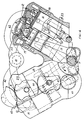
- FIG 2- is a cross-sectional view taken along line A-A of FIG 1 but around the piston crankshaft mechanism and with the lower crankcase removed.
- FIG 3- is a valve timing diagram of the preferred design in power cylinder crank angle degrees with the lines indicating valve open times and with the TDC position shown thereon being the TDC position of the first power piston.
- FIG 4- shows an alternative design which has two units, being in a V configuration and utilizing turbocharging and crankcase compression of the pumping cylinder.
- One unit or bank of cylinders is shown as an end view with the other unit shown as a cross-sectional view taken along line B-B of FIG 5 but around the piston crankshaft mechanism thereof and with partial hidden detail shown and the lower power crankcase and lower RH side pumping cylinder crankcase being removed.
- FIG 5- is a top schematic view of the sectioned unit of FIG 4 and shows the cylinders, ports, combustion chambers and valve opening locations thereof.
- FIG 6- is a valve timing diagram of the alternative design shown in FIGS 4 and 5 and uses the same features as described for FIG 3.
- FIG 7- is a end shematic view of an alternative V configuration and which shows the cylinder and crankshaft locations thereof.
- each said unit has a pumping cylinder 5 with a pumping piston 16 reciprocable therein and first and second power cylinders, respectively 3 and 4 with first and second power pistons respectively 13 and 14 reciprocable within their respective power cylinders.
- All cylinders of a unit share a parallel axis and a common block 18 and a common head 19, whilst the pumping cylinder is evenly distanced to each of the power cylinders.
- a pumping crankshaft 2 and pumping conrod 17 cause reciprocation of the pumping piston 16 and a power crankshaft 1 and power conrods 15 cause reciprocation of the said power pistons.
- a pump drive gear 7 which is fixed to each of the pumping crankshafts 2, cooperates with, is driven by, and is one half the diameter of, the power crankshaft gear 6 which is fixed to the power crankshaft 1.
- This gear arrangement then provides for the pumping pistons 16 to be reciprocated at and cyclicly operated at, twice that of the power pistons.
- the phasing of the power pistons of a unit relative to each other, is one hundred and eighty power 'crankshaft crankangle' (from hereinafter is refered to as 'CA') degrees.
- the crankshafts for carrying out all modes of the invention are of the one piece type whilst all conrods are of the two piece type and bolt on to the respective crankshafts from the underside thereof, for pivotal movement therearound.
- the components and auxiliaries not illustrated for the efficient operation of the engine are included in all modes for carrying out the invention whilst water cooling passages are shown in the sectioned walls of FIGS 2 and 4 but are not numbered to reduce cluttering thereof.
- the respective components of the first and second power cylinders are respectively referred to as the first and second said components, or they are referred to as the respective components of the power cylinder of which the description is directed to.
- the preferred design or mode of carrying out the invention is a naturally aspirated inline version with the pumping cylinder 5 being located in the middle of the first and second power cylinders, respectively 3 and 4.
- the pumping crankshaft 2 is accessed and held in place by pumping crankshaft caps 38 which bolt into the engine block 18 whilst the power crankshaft 1 is accessed and held in place by the lower crankcase which is removed in the FIG 2.
- the phasing of the pumping piston 16 relative to the power pistons 13 and 14 has the pumping piston leading the piston of the power cylinder which the intake charge of that particular pumping cylinder cycle will be transferred into, to TDC, by less than 108 power CA degrees.
- the preferred design has all intake, transfer, and exhaust valves being poppet type valves.
- the first and second combustion chambers respectively 22 and 25, remain in constant communication with their respective power cylinder and each has a spark plug 35 mounted thereinto and which causes ignition of the combustible mixture therein.
- Petrol fuel injection means 36 are mounted into each transfer port and inject a predetermined quantity of fuel thereinto as the said intake charge is being transferred into the power cylinder thereof.
- a first transfer valve 8 times communication between the first transfer port 21 and the first power cylinder 3 whilst a second transfer valve 10 times communication between the second transfer port 24 and the second power cylinder 4.
- Two intake valves 12 time communication between the intake port 20 and the pumping cylinder 5.
- a first exhaust valve 9 times communication between the first power cylinder 3 and the first exhaust port 23 whilst a second exhaust valve 11 times communication between the second power cylinder 4 and the second exhaust port 26.
- the said exhaust ports lead to an exhaust manifold and eventually to an exhaust pipe whilst the said intake port leads to an intake manifold with air metering means therein provided.
- All of the said valves are actuated by a single overhead camshaft which has an axis parallel to that of the crankshafts and is positioned directly above all the said valves so as to directly actuate them.
- the said camshaft is not shown in FIG 2 to reduce cluttering thereof and of the major features thereof.
- the said camshaft is driven by chain means 46 from the camshaft drive sprocket 39 which is fixed to the pumping crankshaft 2.
- the sprocket on the said camshaft which cooperates with the said chain is a half of the diameter as the said camshaft drive gear, providing for the said camshaft to cooperate at the same cyclic speed as the power cylinders and as such, single camlobes actuate the transfer and exhaust valves, whilst two camlobes are evenly spaced around the said camshaft where the intake valves are actuated from, so that the intake valves open twice as often as the other valves and which follows the increased cyclic speed of the pumping cylinder.
- Variable exhaust valve closing event is obtained by a turning block type of valve timing mechanism which is not shown for reasons of undue complexity and which allows for the said valves to close between 162 and 10.8 power CA degrees before TDC depending upon engine load and speed.
- the engine oil pump supplies the oil to the engine and is driven from the oil pump drive gear 40 which is fixed to the power crankshaft 1 between the power cylinders.
- the intake valves 12 open when the pumping piston moves between 0 and 144 pumping CA degrees after TDC. This allows the compressed intake gas of the previous cycle to expand substantially to atmospheric before the said valves 12 are opened.
- 'BDC' 'bottom dead centre'
- the intake air is induced into the pumping cylinder 5.
- the intake valves 12 close and the induction of the intake air ceases.
- One of the transfer valves 21 or 24 begins to open between 72 and 288 pump degrees after TDC, initiating the transfer phase to the respective power cylinder of which the said open transfer valve opens into.
- the said transfer valve then remains open until the pumping piston 16 moves through to 72 pump degrees after TDC which is shown in FIG 3.
- the piston of the pumping cylinder then continues towards BDC, and begins a new cycle thereof as is described above.
- the intake air of the next said cycle is transferred to the other power cylinder and the intake air of the following said cycle and which is after the next said cycle is transferred to the said respective power cylinder starting a new cycle thereof.
- the exhaust valve thereof is open, providing for the later part of the exhaust phase thereof to occur which has the scavenging of the remaining exhaust gases from the said respective cylinder by the transferring intake air.
- the exhaust valve of the said respective power cylinder remains open until the piston thereof moves to between 162 and 10.8 power CA degrees before TDC.
- the fuel is injected into the transfer port of the said respective power cylinder during the transfer phase and at low load and or speed, it is mostly injected after the exhaust valve of that power cylinder has closed. With the fuel injected, a spark at the respective spark plug 35 causes combustion to occur about the TDC position.
- the piston of the said respective power cylinder then moves towards BDC, substantially expanding the gases therein to atmospheric before the exhaust valve begins to open when the said piston is between 90 and 198 power CA degrees after TDC. This then initiates the first part of the exhaust phase being blowdown, and then positive scavenging occurs whilst the piston thereof moves towards TDC until the transfer valve of that cylinder opens, beginning another cycle thereof and as is described above.
- the operation of the other power cylinder is the same as that described above for the said respective power cylinder but as is obvious, it occurs one hundred and eighty power CA degrees before and after it occurs in the said respective cylinder.
- the alternative design or mode for carrying out the invention has two units which are set in a V configuration and with each said unit being one bank of cylinders of the said V.
- the power cylinders of each unit are positioned close together with the pumping cylinder 5 of each unit being positioned on the outside of the said V but being central to the power cylinders of its said unit.
- Constant volume combustion chambers which have communication to their respective power cylinders being timed by secondary valves are used in the alternative design with the first said secondary valve being 27 and the second said secondary valve being 28.
- a turbocharger 41 is positioned in the middle of the said V with the exhaust manifolds 23 of all power cylinders communicating thereto whilst the exhaust, ports 23 and manifolds 23 share the same number.
- the pressurised intake manifold 42 leading from the turbocharger 41 communicates with the intake ports of both pumping cylinders whilst the crankcase intake ports 33 of both pumping cylinders is naturally aspirated.
- a single power crankshaft 1 causes reciprocation of all power pistons whilst each pumping cylinder 5 has its own pumping crankshaft 2.
- a single power crankshaft gear 6 which is fixed to the power crankshaft, cooperates with the pumping cylinder drive gears 7, fixed to each of the pumping crankshafts.
- the phasing of the pumping pistons relative to the power cylinders of a respective unit has the pumping piston leading the said power pistons to TDC by less than 108 power CA degrees.
- the phasing of the power pistons of the unsectioned unit relative to the said pistons of the sectioned unit has the first power piston 3 of the sectioned unit, leading the first power piston of the unsectioned unit, by ninety power CA degrees.
- the power crankshaft 1 is accessed and held in place by the lower power crankcase which is removed in the drawings whilst each pumping crankshaft 2 is accessed and held in place by a pumping lower crankcase 47 which is shown on the unsectioned unit of FIG 4.
- the alternative design has all intake, transfer, exhaust and secondary valves being poppet type valves whilst the crankcase intake valves 32 are reed type valves.
- the first combustion chamber 22 and the first power cylinder 3 has communication therebetween controlled by a first secondary valve 27 whilst the second combustion chamber 25 and the second power cylinder 4 have communication therebetween comtrolled by a second secondary valve 28.
- Diesel fuel injection means 37 are mounted into each said combustion chamber whilst ignition therin is caused by the temperature and pressure of the combustible mixture therein.
- Protrusions 31, on the top of each power piston extend upwards so that they substantially atleast, take up the volumes of each secondary port 29 and 30 which result in an efficiency increase of the engine.
- each unit has the same intake, transfer, and exhaust valve and port arrangements and functions, as are described for the preferred design although the positioning of some valves and ports is altered.
- Each said unit has two overhead camshafts which are not shown in the drawings and which are driven by gear means from the pumping cylinder drive gear 7.
- One of two idler gears 43 cooperates with the said gear 7 whilst the another idler gear 44 cooperates with the idler gear 43 and with the camshaft gear 45 which is the same diameter as the power crankshaft gear 6.
- the said camshaft gear 45 is fixed to the power camshaft which has single camlobes actuating each transfer, secondary, and exhaust valves whilst another gear which is fixed to the said power camshaft cooperates with a gear which is a half the diameter thereof and which is fixed to the pumping camshaft.
- the said pumping camshaft has single camlobes actuating the intake valves with the said diameter difference of the relevant gears providing for the increased cyclic velocity of the intake valves.
- the intake valves 12 begin to open when the pumping piston moves between TDC and 144 pumping CA degrees after TDC. This allows the compressed air from the previous cycle to expand substantially to the pressure of the intake manifold before it opens. With the intake valves 12 opened and the pumping piston moving towards its BDC position, the intake air is induced into the pumping cylinder 5. Whilst the said piston 16 is moving towards BDC, the intake air within the crankcase is compressed.
- the crankcase transfer ports 34 are closed and when the said piston moves between 216 and 14.4 pump degrees before TDC, the intake valves 12 are closed and the induction of the intake air through the intake ports ceases whilst if the engine is operating at low load then on the said pistons up stroke, intake air will be induced into the crankcase through the crankcase intake valves 32.
- One of the transfer valves opens when the pumping piston is between 72 and 288 pump degrees after TDC, to initiate the transfer phase to the respective power cylinder which the said transfer valve opens into. The said transfer valve then remains open until the pumping piston has moved between 72 pump degrees before TDC and 72 pump degrees after TDC.
- the piston of the pumping cylinder then continues towards BDC and begins a new cycle thereof when the intake valves begin to open again between TDC and 144 pump degrees after TDC whilst the intake air of the next said cycle is transferred to the other power cylinder and so forth as is described hereinbefore.
- the secondary valve thereof is open providing for the scavenging of the exhaust gases from the combustion chamber thereof.
- the said secondary valve closes when the piston of that respective power cylinder has moved to one hundred and fifteen power CA degrees before TDC.
- the exhaust valve of the said respective power cylinder is open and closes when the piston thereof has moved to forty five power CA degrees before TDC, allowing for nearly all the exhaust gas to be scavenged from the said cylinder except for a small residual portion thereof remaining.
- the gas from the combustion chamber flows through the secondary port and open valve thereof to expand substantially to atmosperic before the exhaust valve of the said cylinder is opened when the piston thereof is at forty power CA degrees before BDC.
- the operation of the other power cylinder has the same said valve and cyclic operation as that described above for the said respective power cylimder but as is obvious, it occurs 180 power CA degrees before and after it occurs in the said respective cylinder.
- the alternative V configuration of FIG 7 has two units being in the said configuration with each said unit being one bank of cylinders for the said engine whilst the pumping cylinders 5 thereof are located to the inside of the said V, and of the power cylinders.
- a single pumping crankshaft 2 causes reciprocation of both said pumping pistons 16 whilst a single power crankshaft 1 causes reciprocation of all said power cylinders.
Landscapes
- Engineering & Computer Science (AREA)
- Chemical & Material Sciences (AREA)
- Combustion & Propulsion (AREA)
- Mechanical Engineering (AREA)
- General Engineering & Computer Science (AREA)
- Output Control And Ontrol Of Special Type Engine (AREA)
- Supercharger (AREA)
- Lubrication Of Internal Combustion Engines (AREA)
Abstract
Description
- This invention relates to reciprocating piston internal combustion engines of the type wherein, pumping and power cylinders are operated on two stroke cycles.
- Engines of this type have been disclosed in numerous prior art which have intended to improve the efficiency and or power to weight ratio thereof. US,A, PATENT NO 1,881,582 shows a design which has a pumping cylinder driven at twice the cyclic speed of and alternately suppling a intake scavenging charge to two power cylinders, via transfer ports which communicate with the lower cylinder walls of the power cylinders, hence being timed by the power pistons. Although this design marginally increases the scavenging efficiency attainable and as compared to crankcase compression type two stroke engines, this design has and retains numerous efficiency problems of, including the fundamental inefficiency of, the conventional two stroke engine. The said inefficiency results from the opening of the transfer ports in the lower cylinder walls and which reduces the volume through which expansion occurs with the said reduction being used instead for a half of the transfer scavenging phase. Furthermore this design, due to the said transfer to the lower cylinder walls, has no potential for significant efficiency gains to be attained if valve controlled constant volume combustion chambers are to be used.
- A second type of engine which has pumping and power cylinders operating on two stroke cycles and which have intended to overcome the above said undesireable features are typically disclosed in U S PAT NO'S : 3,880,126 and 4,458,635. These designs have the pumping cylinder transferring the intake charge through valve timed ports which open into the power cylinder head section. U S PAT NO : 3,880,126, utilizes a combustion chamber which is in constant communication with the power cylinder and which has an excessive number of components whilst overall efficiency and power output are severley limited by a poor scavenging efficiency which primarily results from the long transfer scavenging phase required of the design. This further exacerbats the obvious power to weight ratio limitations of the design. U S PAT NO: 4,458,635, utilizes a valve controlled constant volume combustion chamber which foregoing the supercharging system used that results in a similar said fundamental inefficiency, increases the scavenging and combustion efficiency and hence overall efficiency is also maginally increased. Subsequently, only an average power to weight ratio results whilst an excessive number of components is still a major problem.
- A further design of engine which shares similiar cylinder, port and valve locations of the presented invention but which is outside of the technical field of this invention in that the power cylinders operate on four stroke cycles, is typically shown in GB,A PATENT NO 2071210. As such the pumping cylinder is used only as a supercharging device and is not necessary for the operation of the engine as is required in the presented invention.
- As acknowledged in the pre-characterising portion of
claim 1 appended hereto, French Patent No. 820925 to GRAB discloses a two-stroke internal combustion engine comprising at least one unit having a pumping cylinder, a pumping piston reciprocally movable in said pumping cylinder, two power cylinders, a respective power piston reciprocally movable in each said power cylinder, each said power cylinder having an associated combustion chamber, the pumping piston reciprocating at a cycle speed twice that of the power pistons, and said power pistons being phased about one stroke apart, a cylinder head closing the top ends of all said cylinders, said cylinder head having two transfer ports therethrough enabling said pumping cylinder to communicate with said power cylinders, transfer valves controlling communication between the pumping cylinder and the power cylinders, at least two exhaust ports allowing exhaust gases to flow from the power cylinders when the associated power piston is at about or before its bottom dead centre position, at least one intake port through the head and communicating with the pumping cylinder, intake valve means associated with the intake port and allowing a major portion of an intake charge to be induced into the pumping cylinder when the pumping piston is moving away from its top dead centre position and said pumping piston alternately transferring the intake charge into the power cylinders through the transfer ports as the pumping piston moves towards its top dead centre position, said pumping piston leading to the top dead centre position the power piston of the cylinder to which the charge is transferred. - The fixed geometry of the ported portion of the GRAB engine means that exhaust timing is dependent upon piston position such that opening and closing events are interdependent and exhaust open timing cannot be decided without consideration to duration or closing. Further, the exhaust timing is necessarily restricted to being symmetrical about BDC; as such, exhaust timing is compromised. Also, the engine of GRAB employs an axial flow scavenging motion.
- A further problem of the GRAB engine is that its exhaust timing cannot be controlled and manipulated in operation as the engine is traversing its load range. Thus, for example, the scavenging and trapping efficiencies of the engine, that is, the amounts of fresh charge and retained exhaust gas trapped in the cylinder ready for combustion, cannot be controlled and manipulated by control of the exhaust opening and closing events.
- More generally, the ports used by GRAB require the cutting of holes in the cylinder walls. These holes would be detrimental to the life of the piston ring and would cause premature wear and degradation of the sealing efficiency of the engine leading to early failure and increased pollution throughout the engine's life. This point is critical in view of increasingly stringent exhaust emissions legislation around the world. For example, the US Clean Air Act 1990 requires that vehicle engines must endure at least 100,000 miles (160,000 kilometres) from new without significant increase in tailpipe emissions. It is believed that, to date, no ported engine has succeeded in passing these requirements.
- The present invention is characterised in that: the flow of the exhaust gases through the exhaust ports is controlled by exhaust poppet valves; the exhaust ports extend through said head; the exhaust valves begin to open when the power piston is positioned between 90 degrees after top dead centre and 198 degrees after top dead centre and close when the power piston is positioned between 162 degrees before top dead centre and 10.8 degrees before top dead centre; the transfer valves are poppet valves; the transfer valves begin to open when the pumping piston is positioned between 72 degrees after top dead centre and 288 degrees after top dead centre and close when the pumping piston is positioned between 72 degrees before top dead centre and 72 degrees after top dead centre; each exhaust valve closes before the associated transfer valve closes; the intake valve means begin to open when the pumping piston is positioned between top dead centre and 144 degrees after top dead centre and close when the pumping piston is positioned between 216 degrees before top dead centre and 14.4 degrees before top dead centre; and the pumping piston leads the power piston to which the intake charge is to be transferred to the top dead centre position by less than 108 power piston degrees before top dead centre.
- The invention provides a novel engine design which significantly increases the thermal efficiency, power to weight ratio and scavenging efficiency of all the abovesaid engine types. Further, the number of components required for the abovesaid second type of engine is reduced.
- Advantageous optional features of the invention are set forth in
claims 2 to 17 appended hereto. - FIG 1- is a top schematic view of the preferred design which is a inline single unit and showing the cylinders, ports, combustion chamber and valve opening locations thereof.
- FIG 2- is a cross-sectional view taken along line A-A of FIG 1 but around the piston crankshaft mechanism and with the lower crankcase removed.
- FIG 3- is a valve timing diagram of the preferred design in power cylinder crank angle degrees with the lines indicating valve open times and with the TDC position shown thereon being the TDC position of the first power piston.
- FIG 4- shows an alternative design which has two units, being in a V configuration and utilizing turbocharging and crankcase compression of the pumping cylinder. One unit or bank of cylinders is shown as an end view with the other unit shown as a cross-sectional view taken along line B-B of FIG 5 but around the piston crankshaft mechanism thereof and with partial hidden detail shown and the lower power crankcase and lower RH side pumping cylinder crankcase being removed.
- FIG 5- is a top schematic view of the sectioned unit of FIG 4 and shows the cylinders, ports, combustion chambers and valve opening locations thereof.
- FIG 6- is a valve timing diagram of the alternative design shown in FIGS 4 and 5 and uses the same features as described for FIG 3.
- FIG 7- is a end shematic view of an alternative V configuration and which shows the cylinder and crankshaft locations thereof.
- Refering to all modes for carrying out the present invention, each said unit has a pumping
cylinder 5 with apumping piston 16 reciprocable therein and first and second power cylinders, respectively 3 and 4 with first and second power pistons respectively 13 and 14 reciprocable within their respective power cylinders. All cylinders of a unit share a parallel axis and acommon block 18 and acommon head 19, whilst the pumping cylinder is evenly distanced to each of the power cylinders. Apumping crankshaft 2 and pumpingconrod 17 cause reciprocation of thepumping piston 16 and apower crankshaft 1 andpower conrods 15 cause reciprocation of the said power pistons. Each said crankshaft is supported for rotation by bearing means whilst journal means which are not shown in the drawings, provide pivotal movement at the conrod crankshaft pivots and the conrod piston pivot. Apump drive gear 7 which is fixed to each of thepumping crankshafts 2, cooperates with, is driven by, and is one half the diameter of, thepower crankshaft gear 6 which is fixed to thepower crankshaft 1. This gear arrangement then provides for thepumping pistons 16 to be reciprocated at and cyclicly operated at, twice that of the power pistons. The phasing of the power pistons of a unit relative to each other, is one hundred and eighty power 'crankshaft crankangle' (from hereinafter is refered to as 'CA') degrees. The first and second transfer ports respectively 21 and 24, remain in constant communication with the pumping cylinder. The crankshafts for carrying out all modes of the invention, are of the one piece type whilst all conrods are of the two piece type and bolt on to the respective crankshafts from the underside thereof, for pivotal movement therearound. Of course the components and auxiliaries not illustrated for the efficient operation of the engine, are included in all modes for carrying out the invention whilst water cooling passages are shown in the sectioned walls of FIGS 2 and 4 but are not numbered to reduce cluttering thereof. Furthermore, the respective components of the first and second power cylinders are respectively referred to as the first and second said components, or they are referred to as the respective components of the power cylinder of which the description is directed to. - Referring now to FIGS 1-3, the preferred design or mode of carrying out the invention is a naturally aspirated inline version with the pumping
cylinder 5 being located in the middle of the first and second power cylinders, respectively 3 and 4. Thepumping crankshaft 2 is accessed and held in place by pumpingcrankshaft caps 38 which bolt into theengine block 18 whilst thepower crankshaft 1 is accessed and held in place by the lower crankcase which is removed in the FIG 2. The phasing of thepumping piston 16 relative to thepower pistons - The preferred design has all intake, transfer, and exhaust valves being poppet type valves. The first and second combustion chambers respectively 22 and 25, remain in constant communication with their respective power cylinder and each has a
spark plug 35 mounted thereinto and which causes ignition of the combustible mixture therein. Petrol fuel injection means 36 are mounted into each transfer port and inject a predetermined quantity of fuel thereinto as the said intake charge is being transferred into the power cylinder thereof. A first transfer valve 8 times communication between thefirst transfer port 21 and thefirst power cylinder 3 whilst asecond transfer valve 10 times communication between the second transfer port 24 and thesecond power cylinder 4. - Two
intake valves 12 time communication between theintake port 20 and the pumpingcylinder 5. Afirst exhaust valve 9 times communication between thefirst power cylinder 3 and thefirst exhaust port 23 whilst asecond exhaust valve 11 times communication between thesecond power cylinder 4 and thesecond exhaust port 26. The said exhaust ports lead to an exhaust manifold and eventually to an exhaust pipe whilst the said intake port leads to an intake manifold with air metering means therein provided. All of the said valves are actuated by a single overhead camshaft which has an axis parallel to that of the crankshafts and is positioned directly above all the said valves so as to directly actuate them. The said camshaft is not shown in FIG 2 to reduce cluttering thereof and of the major features thereof. The said camshaft is driven by chain means 46 from thecamshaft drive sprocket 39 which is fixed to the pumpingcrankshaft 2. The sprocket on the said camshaft which cooperates with the said chain is a half of the diameter as the said camshaft drive gear, providing for the said camshaft to cooperate at the same cyclic speed as the power cylinders and as such, single camlobes actuate the transfer and exhaust valves, whilst two camlobes are evenly spaced around the said camshaft where the intake valves are actuated from, so that the intake valves open twice as often as the other valves and which follows the increased cyclic speed of the pumping cylinder. Variable exhaust valve closing event is obtained by a turning block type of valve timing mechanism which is not shown for reasons of undue complexity and which allows for the said valves to close between 162 and 10.8 power CA degrees before TDC depending upon engine load and speed. The engine oil pump supplies the oil to the engine and is driven from the oil pump drive gear 40 which is fixed to thepower crankshaft 1 between the power cylinders. - The method of operation including the valve timings of the preferred design is now described. The
intake valves 12 open when the pumping piston moves between 0 and 144 pumping CA degrees after TDC. This allows the compressed intake gas of the previous cycle to expand substantially to atmospheric before the saidvalves 12 are opened. With theintake valves 12 opened and the pumping piston moving towards its 'bottom dead centre' (which hereinafter is referred to as 'BDC') position, the intake air is induced into thepumping cylinder 5. As the saidpiston 16 moves through 36 pump degrees before BDC theintake valves 12 close and the induction of the intake air ceases. One of thetransfer valves 21 or 24 begins to open between 72 and 288 pump degrees after TDC, initiating the transfer phase to the respective power cylinder of which the said open transfer valve opens into. The said transfer valve then remains open until thepumping piston 16 moves through to 72 pump degrees after TDC which is shown in FIG 3. The piston of the pumping cylinder then continues towards BDC, and begins a new cycle thereof as is described above. The intake air of the next said cycle is transferred to the other power cylinder and the intake air of the following said cycle and which is after the next said cycle is transferred to the said respective power cylinder starting a new cycle thereof. - During the first part of the transfer phase to the said respective power cylinder, the exhaust valve thereof is open, providing for the later part of the exhaust phase thereof to occur which has the scavenging of the remaining exhaust gases from the said respective cylinder by the transferring intake air. The exhaust valve of the said respective power cylinder remains open until the piston thereof moves to between 162 and 10.8 power CA degrees before TDC. At high load and or high speed, the fuel is injected into the transfer port of the said respective power cylinder during the transfer phase and at low load and or speed, it is mostly injected after the exhaust valve of that power cylinder has closed. With the fuel injected, a spark at the
respective spark plug 35 causes combustion to occur about the TDC position. The piston of the said respective power cylinder then moves towards BDC, substantially expanding the gases therein to atmospheric before the exhaust valve begins to open when the said piston is between 90 and 198 power CA degrees after TDC. This then initiates the first part of the exhaust phase being blowdown, and then positive scavenging occurs whilst the piston thereof moves towards TDC until the transfer valve of that cylinder opens, beginning another cycle thereof and as is described above. The operation of the other power cylinder is the same as that described above for the said respective power cylinder but as is obvious, it occurs one hundred and eighty power CA degrees before and after it occurs in the said respective cylinder. - Referring now to FIGS 4-6, the alternative design or mode for carrying out the invention has two units which are set in a V configuration and with each said unit being one bank of cylinders of the said V. The power cylinders of each unit, are positioned close together with the
pumping cylinder 5 of each unit being positioned on the outside of the said V but being central to the power cylinders of its said unit. Constant volume combustion chambers which have communication to their respective power cylinders being timed by secondary valves are used in the alternative design with the first said secondary valve being 27 and the second said secondary valve being 28. A turbocharger 41 is positioned in the middle of the said V with the exhaust manifolds 23 of all power cylinders communicating thereto whilst the exhaust,ports 23 andmanifolds 23 share the same number. The pressurisedintake manifold 42 leading from the turbocharger 41 communicates with the intake ports of both pumping cylinders whilst the crankcase intake ports 33 of both pumping cylinders is naturally aspirated. Asingle power crankshaft 1 causes reciprocation of all power pistons whilst eachpumping cylinder 5 has itsown pumping crankshaft 2. A singlepower crankshaft gear 6 which is fixed to the power crankshaft, cooperates with the pumping cylinder drive gears 7, fixed to each of the pumping crankshafts. The phasing of the pumping pistons relative to the power cylinders of a respective unit, has the pumping piston leading the said power pistons to TDC by less than 108 power CA degrees. The phasing of the power pistons of the unsectioned unit relative to the said pistons of the sectioned unit, has thefirst power piston 3 of the sectioned unit, leading the first power piston of the unsectioned unit, by ninety power CA degrees. Thepower crankshaft 1 is accessed and held in place by the lower power crankcase which is removed in the drawings whilst each pumpingcrankshaft 2 is accessed and held in place by a pumpinglower crankcase 47 which is shown on the unsectioned unit of FIG 4. - The alternative design has all intake, transfer, exhaust and secondary valves being poppet type valves whilst the
crankcase intake valves 32 are reed type valves. Thefirst combustion chamber 22 and thefirst power cylinder 3 has communication therebetween controlled by a firstsecondary valve 27 whilst thesecond combustion chamber 25 and thesecond power cylinder 4 have communication therebetween comtrolled by a secondsecondary valve 28. Diesel fuel injection means 37 are mounted into each said combustion chamber whilst ignition therin is caused by the temperature and pressure of the combustible mixture therein.Protrusions 31, on the top of each power piston, extend upwards so that they substantially atleast, take up the volumes of eachsecondary port cylinder drive gear 7. One of two idler gears 43 cooperates with the saidgear 7 whilst the anotheridler gear 44 cooperates with the idler gear 43 and with thecamshaft gear 45 which is the same diameter as thepower crankshaft gear 6. The saidcamshaft gear 45 is fixed to the power camshaft which has single camlobes actuating each transfer, secondary, and exhaust valves whilst another gear which is fixed to the said power camshaft cooperates with a gear which is a half the diameter thereof and which is fixed to the pumping camshaft. The said pumping camshaft has single camlobes actuating the intake valves with the said diameter difference of the relevant gears providing for the increased cyclic velocity of the intake valves. - The method of operation including the valve timings of the alternative mode is now described with reference to a single unit. The
intake valves 12 begin to open when the pumping piston moves between TDC and 144 pumping CA degrees after TDC. This allows the compressed air from the previous cycle to expand substantially to the pressure of the intake manifold before it opens. With theintake valves 12 opened and the pumping piston moving towards its BDC position, the intake air is induced into thepumping cylinder 5. Whilst the saidpiston 16 is moving towards BDC, the intake air within the crankcase is compressed. If the engine is operating above or about, fifty percent of its possible load, then the turbocharger 41 is operating efficiently, and as the pumping piston uncovers the crankcase transfer ports 34 between 72 and 288 pump degrees after TDC, then no crankcase transfer occurs as the pressure in the said cylinder resulting from the turbocharger 41 is as high or higher than that of the said crankcase. This then provides for the said crankcase compression to be utilised at the lower loads but not at the higher loads as well as minimising the maximum pressures attained in the said crankcase which then reduces the sealing requirement thereof and allowing for lighter said reed valve materials with lower opening pressures. As the saidpiston 16 moves between 72 pump degrees before TDC and 72 pump degrees after TDC, the crankcase transfer ports 34 are closed and when the said piston moves between 216 and 14.4 pump degrees before TDC, theintake valves 12 are closed and the induction of the intake air through the intake ports ceases whilst if the engine is operating at low load then on the said pistons up stroke, intake air will be induced into the crankcase through thecrankcase intake valves 32. One of the transfer valves opens when the pumping piston is between 72 and 288 pump degrees after TDC, to initiate the transfer phase to the respective power cylinder which the said transfer valve opens into. The said transfer valve then remains open until the pumping piston has moved between 72 pump degrees before TDC and 72 pump degrees after TDC. The piston of the pumping cylinder then continues towards BDC and begins a new cycle thereof when the intake valves begin to open again between TDC and 144 pump degrees after TDC whilst the intake air of the next said cycle is transferred to the other power cylinder and so forth as is described hereinbefore. - During the first part of the transfer phase to the respective power cylinder, the secondary valve thereof is open providing for the scavenging of the exhaust gases from the combustion chamber thereof. The said secondary valve closes when the piston of that respective power cylinder has moved to one hundred and fifteen power CA degrees before TDC. During this time the exhaust valve of the said respective power cylinder is open and closes when the piston thereof has moved to forty five power CA degrees before TDC, allowing for nearly all the exhaust gas to be scavenged from the said cylinder except for a small residual portion thereof remaining. This is retained to highly pressurise the remaining gas so that when the secondary valve reopens when the piston thereof is at five power CA degrees before TDC, the pressure in the power cylinder is not significantly lower than that of the combustion chamber thereof which would decrease the thermal efficiency attainable. When the said piston is positioned about forty power CA degrees before TDC, diesel type fuel is injected into the said combustion chamber which results in combustion occuring just after the said relevant transfer valve has closed and so that as the said secondary valve thereof is opened, about fifty percent or more of the combustible mass has been combusted. With combustion completed and the said power piston moving towards BDC, the gas from the combustion chamber flows through the secondary port and open valve thereof to expand substantially to atmosperic before the exhaust valve of the said cylinder is opened when the piston thereof is at forty power CA degrees before BDC. This initiates the exhaust phase of the said cylinder and as the piston thereof moves towards TDC, it positively scavenges the said cylinder untill the next transfer phase thereinto begins which starts the next cycle thereof and as is described above. The operation of the other power cylinder has the same said valve and cyclic operation as that described above for the said respective power cylimder but as is obvious, it occurs 180 power CA degrees before and after it occurs in the said respective cylinder.
- The alternative V configuration of FIG 7 has two units being in the said configuration with each said unit being one bank of cylinders for the said engine whilst the
pumping cylinders 5 thereof are located to the inside of the said V, and of the power cylinders. Asingle pumping crankshaft 2 causes reciprocation of both saidpumping pistons 16 whilst asingle power crankshaft 1 causes reciprocation of all said power cylinders.
Claims (17)
- A two-stroke internal combustion engine comprising at least one unit having a pumping cylinder (5), a pumping piston (16) reciprocally movable in said pumping cylinder (5), two power cylinders (3, 4), a respective power piston (13, 14) reciprocally movable in each said power cylinder (3, 4), each said power cylinder (3, 4) having an associated combustion chamber (22, 25), the pumping piston (16) reciprocating at a cycle speed twice that of the power pistons (13, 14) and said power pistons (13, 14) being phased about one stroke apart, a cylinder head (19) closing the top ends of all said cylinders (3, 4, 5), said cylinder head (19) having two transfer ports (21, 24) therethrough enabling said pumping cylinder (5) to communicate with said power cylinders (3, 4), transfer valves (8, 10) controlling communication between the pumping cylinder (5) and the power cylinders (3, 4), at least two exhaust ports (23, 26) allowing exhaust gases to flow from the power cylinders (3, 4) when the associated power piston (13, 14) is at about or before its bottom dead centre position, at least one intake port (20) through the head (19) and communicating with the pumping cylinder (5), intake valve means (12) associated with the intake port (20) and allowing a major portion of an intake charge to be induced into the pumping cylinder (5) when the pumping piston (16) is moving away from its top dead centre position and said pumping piston (16) alternately transferring the intake charge into the power cylinders (3, 4) through the transfer ports (21, 24) as the pumping piston (16) moves towards its top dead centre position, said pumping piston (16) leading to the top dead centre position the power piston (13, 14) of the cylinder to which the charge is transferred, characterised in that:
the flow of the exhaust gases through the exhaust ports (23, 26) is controlled by exhaust poppet valves (9, 11);
the exhaust ports (23, 26) extend through said head;
the exhaust valves (9, 11) begin to open when the power piston (13, 14) is positioned between 90 degrees after top dead centre and 198 degrees after top dead centre and close when the power piston (13, 14) is positioned between 162 degrees before top dead centre and 10.8 degrees before top dead centre;
the transfer valves (8, 10) are poppet valves;
the transfer valves (8, 10) begin to open when the pumping piston (16) is positioned between 72 degrees after top dead centre and 288 degrees after top dead centre and close when the pumping piston (16) is positioned between 72 degrees before top dead centre and 72 degrees after top dead centre;
each exhaust valve (9, 11) closes before the associated transfer valve (8, 10) closes;
the intake valve means begin to open when the pumping piston (16) is positioned between top dead centre and 144 degrees after top dead centre and close when the pumping piston (16) is positioned between 216 degrees before top dead centre and 14.4 degrees before top dead centre; and
the pumping piston (16) leads the power piston (13, 14) to which the intake charge is to be transferred to the top dead centre position by less than 108 power piston (13, 14) degrees before top dead centre. - The engine of claim 1 wherein said power pistons (13, 14) are reciprocated by a mainshaft, said mainshaft causes reciprocation of said pumping piston (16), and the pumping cylinder (5) is spaced substantially equal distances from each said power cylinder (3, 4).
- The engine of claim 2 wherein the combustion chambers (22, 25) are in constant communication with their respective said power cylinders (3, 4).
- The engine of claim 2 including a respective secondary valve (27, 28) defining a constant volume combustion chamber (22, 25) between it and the associated said transfer valve (8, 10), said secondary valves (27, 28) time communication between the combustion chambers and the power cylinders (3, 4), the secondary valve (27, 28) of an associated power piston (13, 14) begins to open when said power piston (13, 14) is between 86 degrees before its top dead centre position and 94 degrees after its top dead centre position and closes when the pumping piston (16) is positioned between 288 degrees before top dead centre and its top dead centre position.
- The engine of claim 4, wherein said pumping piston (16) performs substantially all of the compressive work, said transfer valve (8, 10) and the associated said secondary valve (27, 28) close about when combustion commences and the secondary valve (27, 28) closes about when the associated said transfer valve (8, 10) opens.
- The engine of claim 3 wherein said transfer and exhaust valves have a valve head, said valve heads of the transfer and the exhaust valves being located at least substantially axially above the associated power cylinder (3, 4) and to one side thereof, said heads of the transfer valves (8, 10) being located higher in the cylinder head (19) than the heads of the exhaust valves, walls of the combustion chamber (22, 25) from around the transfer valves (8, 10) extending substantially towards the mainshaft so that the walls act to direct the charge from the chamber in a downward direction and said pumping piston (16) performs only part of the compressive work on the charge.
- The engine of claim 2 wherein the pumping piston (16) is reciprocated by a shaft (2) driven from the mainshaft (1) and the pumping piston shaft (2) has a longitudinal axis located above a longitudinal axis of the mainshaft (1), said cylinders (3, 4, 5) have longitudinal axes parallel to one another.
- The engine of claim 2 wherein the pumping piston (16) is reciprocated by a shaft (2) driven from the mainshaft (1), said pumping piston shaft (2) including drive means (46) for operating said valves or other engine auxiliary device.
- The engine of claim 2 wherein that portion of the mainshaft between said power cylinders (13, 14) includes means for driving valves or other engine auxiliary device.
- The engine of claim 1 wherein said pumping cylinder (5) is located within the engine at a higher location than said power cylinders (3, 4).
- The engine of claim 1 including two or more said units arranged in a V configuration with all said power pistons (13, 14) being reciprocated by a common said mainshaft (1) and said pumping piston (16) being reciprocated by a separate shaft (2).
- The engine of claim 1 including a crankcase (47), transfer ports (34) in a lower portion of the pumping cylinder (5) for communicating with the crankcase (47), said transfer ports (34) in said pumping cylinder (5) being uncovered when said pumping piston (16) is near its bottom dead centre position and crankcase intake valve means (32) timing the communication between a crankcase intake port (33) and said crankcase (47) so that a charge is induced while the pumping piston (16) is moving towards its top dead centre position.
- The engine of claim 2 wherein the pumping cylinder (5) is positioned between the power cylinders (3, 4) and the distance between said power cylinders (3, 4) is less than the sum of the pumping cylinder (5) bore and two wall thicknesses separating the pumping cylinder (5) and one said power cylinder (3, 4), the engine further including a turbocharger (41) coupled to an exhaust manifold (23) of each said power cylinder (3, 4).
- The engine of claim 13 including a pressurised intake manifold (42) leading from the turbocharger (41) and communicating with the pumping cylinder intake port (20) and wherein said crankcase intake port (33) is naturally aspirated.
- The engine of claim 2 wherein said intake valve means (12) closes when said pumping piston (16) is positioned between 108 degrees before top dead centre and 72 degrees before top dead centre and said transfer valves (8, 10) open when the pumping piston (16) is positioned between 108 degrees after top dead centre and 288 degrees after top dead centre.
- The engine of claim 2 including a variable valve timing mechanism.
- The engine of claim 6 wherein the walls of the combustion chamber (22, 25) which direct the charge downwardly define a major portion of the volume of the combustion chamber (22, 25).
Applications Claiming Priority (4)
| Application Number | Priority Date | Filing Date | Title |
|---|---|---|---|
| AU4785/89 | 1989-06-16 | ||
| AUPJ478589 | 1989-06-16 | ||
| PCT/AU1990/000261 WO1990015917A1 (en) | 1989-06-16 | 1990-06-15 | Reciprocating piston engine with pumping and power cylinders |
| AU58184/90A AU638720B2 (en) | 1989-06-16 | 1990-06-15 | Reciprocating piston engine with pumping and power cylinders |
Publications (3)
| Publication Number | Publication Date |
|---|---|
| EP0476010A1 EP0476010A1 (en) | 1992-03-25 |
| EP0476010A4 EP0476010A4 (en) | 1992-06-03 |
| EP0476010B1 true EP0476010B1 (en) | 1995-08-23 |
Family
ID=25631974
Family Applications (1)
| Application Number | Title | Priority Date | Filing Date |
|---|---|---|---|
| EP90909109A Expired - Lifetime EP0476010B1 (en) | 1989-06-16 | 1990-06-15 | Reciprocating piston engine with pumping and power cylinders |
Country Status (3)
| Country | Link |
|---|---|
| EP (1) | EP0476010B1 (en) |
| AU (1) | AU638720B2 (en) |
| WO (1) | WO1990015917A1 (en) |
Cited By (1)
| Publication number | Priority date | Publication date | Assignee | Title |
|---|---|---|---|---|
| US10941712B2 (en) | 2015-06-30 | 2021-03-09 | Innio Jenbacher Gmbh & Co Og | Internal combustion engine with a regulating device |
Families Citing this family (23)
| Publication number | Priority date | Publication date | Assignee | Title |
|---|---|---|---|---|
| GB2265942A (en) * | 1992-04-08 | 1993-10-13 | Frederick Arthur Summerlin | Split cycle I.C.engine. |
| KR940002482A (en) * | 1992-07-23 | 1994-02-17 | 김정규 | 2-stroke high-power engine |
| AU688442B2 (en) * | 1994-02-28 | 1998-03-12 | Dmitri Miroshnik | Internal combustion engine |
| US7222614B2 (en) | 1996-07-17 | 2007-05-29 | Bryant Clyde C | Internal combustion engine and working cycle |
| US6951211B2 (en) | 1996-07-17 | 2005-10-04 | Bryant Clyde C | Cold air super-charged internal combustion engine, working cycle and method |
| US7281527B1 (en) | 1996-07-17 | 2007-10-16 | Bryant Clyde C | Internal combustion engine and working cycle |
| AU767475B2 (en) * | 1998-11-09 | 2003-11-13 | Rotec Design Ltd | Two-stroke engine |
| AUPP700398A0 (en) * | 1998-11-09 | 1998-12-03 | Rotec Design Pty Ltd | Improvements to engines |
| IT1311171B1 (en) | 1999-12-21 | 2002-03-04 | Automac Sas Di Bigi Ing Mauriz | ALTERNATIVE THERMAL MOTOR EQUIPPED WITH BALANCING AND PRECOMPRESSION |
| ITMI20011625A1 (en) * | 2001-07-26 | 2003-01-26 | Piaggio & C Spa | TWO STROKE ENGINE WITH INTERNAL COMBUSTION AND DIRECT INJECTION PNEUMATICALLY ASSISTED |
| US6880501B2 (en) | 2001-07-30 | 2005-04-19 | Massachusetts Institute Of Technology | Internal combustion engine |
| US6789514B2 (en) | 2001-07-30 | 2004-09-14 | Massachusetts Institute Of Technology | Internal combustion engine |
| US7178492B2 (en) | 2002-05-14 | 2007-02-20 | Caterpillar Inc | Air and fuel supply system for combustion engine |
| US7201121B2 (en) | 2002-02-04 | 2007-04-10 | Caterpillar Inc | Combustion engine including fluidically-driven engine valve actuator |
| US6688280B2 (en) | 2002-05-14 | 2004-02-10 | Caterpillar Inc | Air and fuel supply system for combustion engine |
| US7252054B2 (en) | 2002-05-14 | 2007-08-07 | Caterpillar Inc | Combustion engine including cam phase-shifting |
| US7191743B2 (en) | 2002-05-14 | 2007-03-20 | Caterpillar Inc | Air and fuel supply system for a combustion engine |
| US20040177837A1 (en) * | 2003-03-11 | 2004-09-16 | Bryant Clyde C. | Cold air super-charged internal combustion engine, working cycle & method |
| RU2261341C2 (en) * | 2003-06-16 | 2005-09-27 | Помогаев Анатолий Васильевич | Internal combustion engine |
| MY144690A (en) * | 2003-06-20 | 2011-10-31 | Scuderi Group Llc | Split-cycle four-stroke engine |
| RU2254487C1 (en) * | 2003-10-28 | 2005-06-20 | Ерегин Николай Васильевич | Internal combustion engine |
| WO2012062291A2 (en) * | 2010-06-18 | 2012-05-18 | Seneca International Ag | Internal combustion engine |
| GB201212449D0 (en) * | 2012-07-12 | 2012-08-29 | Milladale Ltd | Compound engine |
Citations (1)
| Publication number | Priority date | Publication date | Assignee | Title |
|---|---|---|---|---|
| FR771188A (en) * | 1933-04-06 | 1934-10-02 | Telefunken Gmbh | Method for controlling a braking field lamp without expenditure of energy |
Family Cites Families (6)
| Publication number | Priority date | Publication date | Assignee | Title |
|---|---|---|---|---|
| GB169799A (en) * | 1920-07-03 | 1921-10-03 | Waldo George Gernandt | Improvements in internal combustion engines |
| GB265227A (en) * | 1926-01-29 | 1927-08-25 | Marino Vicentini | Improvements in and relating to the working and construction of four-stroke cycle explosion motors for less volatile fuels |
| US1881582A (en) * | 1930-05-07 | 1932-10-11 | Mack T Holloway | Two-cycle gas engine |
| FR820925A (en) * | 1936-04-24 | 1937-11-22 | Two-stroke combustion engine comprising one or more engine cylinders supplied by a charging pump | |
| FR2444161A1 (en) * | 1978-12-15 | 1980-07-11 | Georgopoulos Georges | Two=stroke IC engine - has two power cylinders receiving precompressed explosive charge from auxiliary cylinder |
| DE3007746A1 (en) * | 1980-02-29 | 1981-09-17 | Benno Campione Lugano Kaltenegger | INTERNAL COMBUSTION ENGINE |
-
1990
- 1990-06-15 AU AU58184/90A patent/AU638720B2/en not_active Expired
- 1990-06-15 EP EP90909109A patent/EP0476010B1/en not_active Expired - Lifetime
- 1990-06-15 WO PCT/AU1990/000261 patent/WO1990015917A1/en not_active Ceased
Patent Citations (1)
| Publication number | Priority date | Publication date | Assignee | Title |
|---|---|---|---|---|
| FR771188A (en) * | 1933-04-06 | 1934-10-02 | Telefunken Gmbh | Method for controlling a braking field lamp without expenditure of energy |
Cited By (1)
| Publication number | Priority date | Publication date | Assignee | Title |
|---|---|---|---|---|
| US10941712B2 (en) | 2015-06-30 | 2021-03-09 | Innio Jenbacher Gmbh & Co Og | Internal combustion engine with a regulating device |
Also Published As
| Publication number | Publication date |
|---|---|
| EP0476010A1 (en) | 1992-03-25 |
| AU5818490A (en) | 1991-01-08 |
| WO1990015917A1 (en) | 1990-12-27 |
| EP0476010A4 (en) | 1992-06-03 |
| AU638720B2 (en) | 1993-07-08 |
Similar Documents
| Publication | Publication Date | Title |
|---|---|---|
| US5265564A (en) | Reciprocating piston engine with pumping and power cylinders | |
| EP0476010B1 (en) | Reciprocating piston engine with pumping and power cylinders | |
| US5076220A (en) | Internal combustion engine | |
| US4708107A (en) | Compact pressure-boosted internal combustion engine | |
| US4276858A (en) | Two-cycle internal combustion engine | |
| US2302442A (en) | Internal combustion engine | |
| US4641616A (en) | Internal combustion engine | |
| US4993372A (en) | Two stroke internal combustion engine with decompression valve | |
| WO2000070211B1 (en) | Low emissions two-cycle internal combustion engine | |
| US4986224A (en) | Four cycle diesel engine with pressurized air cooling system | |
| CA2060203C (en) | Reciprocating piston engine with pumping and power cylinders | |
| US4599863A (en) | Compound internal combustion and external combustion engine | |
| US5992375A (en) | Four-stroke cycle internal combustion engine | |
| US20040035377A1 (en) | Two-stroke cycle, free piston, shaft power engine | |
| US2937630A (en) | Compound internal combustion engine | |
| EP0663523A1 (en) | Internal combustion engine | |
| US4096835A (en) | Internal combustion engine method and apparatus | |
| US4938192A (en) | Piston cylinder combination with engine cylinder wall having valve ports and combustion chamber | |
| US5603291A (en) | Internal combustion engine with valve built into piston head | |
| JPH0216324A (en) | Two cycle engine | |
| GB2130641A (en) | Crankcase charged four-stroke I.C. engine | |
| US5870980A (en) | Stepped piston internal combustion engine | |
| RU2139431C1 (en) | Internal combustion engine | |
| GB2149006A (en) | Engine and compressor valve gear | |
| WO1985002655A1 (en) | Internal combustion engine |
Legal Events
| Date | Code | Title | Description |
|---|---|---|---|
| PUAI | Public reference made under article 153(3) epc to a published international application that has entered the european phase |
Free format text: ORIGINAL CODE: 0009012 |
|
| 17P | Request for examination filed |
Effective date: 19911210 |
|
| AK | Designated contracting states |
Kind code of ref document: A1 Designated state(s): AT BE CH DE DK ES FR GB IT LI LU NL SE |
|
| A4 | Supplementary search report drawn up and despatched |
Effective date: 19920413 |
|
| AK | Designated contracting states |
Kind code of ref document: A4 Designated state(s): AT BE CH DE DK ES FR GB IT LI LU NL SE |
|
| 17Q | First examination report despatched |
Effective date: 19930316 |
|
| RAP1 | Party data changed (applicant data changed or rights of an application transferred) |
Owner name: ROTEC ENGINES PTY. LTD. |
|
| GRAA | (expected) grant |
Free format text: ORIGINAL CODE: 0009210 |
|
| AK | Designated contracting states |
Kind code of ref document: B1 Designated state(s): AT BE CH DE DK ES FR GB IT LI LU NL SE |
|
| PG25 | Lapsed in a contracting state [announced via postgrant information from national office to epo] |
Ref country code: IT Free format text: LAPSE BECAUSE OF FAILURE TO SUBMIT A TRANSLATION OF THE DESCRIPTION OR TO PAY THE FEE WITHIN THE PRE;WARNING: LAPSES OF ITALIAN PATENTS WITH EFFECTIVE DATE BEFORE 2007 MAY HAVE OCCURRED AT ANY TIME BEFORE 2007. THE CORRECT EFFECTIVE DATE MAY BE DIFFERENT FROM THE ONE RECORDED.SCRIBED TIME-LIMIT Effective date: 19950823 Ref country code: NL Free format text: LAPSE BECAUSE OF FAILURE TO SUBMIT A TRANSLATION OF THE DESCRIPTION OR TO PAY THE FEE WITHIN THE PRESCRIBED TIME-LIMIT Effective date: 19950823 Ref country code: DK Effective date: 19950823 Ref country code: CH Effective date: 19950823 Ref country code: LI Effective date: 19950823 Ref country code: ES Free format text: THE PATENT HAS BEEN ANNULLED BY A DECISION OF A NATIONAL AUTHORITY Effective date: 19950823 Ref country code: BE Effective date: 19950823 Ref country code: AT Effective date: 19950823 |
|
| REF | Corresponds to: |
Ref document number: 126863 Country of ref document: AT Date of ref document: 19950915 Kind code of ref document: T |
|
| REF | Corresponds to: |
Ref document number: 69021878 Country of ref document: DE Date of ref document: 19950928 |
|
| REG | Reference to a national code |
Ref country code: CH Ref legal event code: PL |
|
| PG25 | Lapsed in a contracting state [announced via postgrant information from national office to epo] |
Ref country code: SE Effective date: 19951123 |
|
| ET | Fr: translation filed | ||
| NLV1 | Nl: lapsed or annulled due to failure to fulfill the requirements of art. 29p and 29m of the patents act | ||
| PLBE | No opposition filed within time limit |
Free format text: ORIGINAL CODE: 0009261 |
|
| STAA | Information on the status of an ep patent application or granted ep patent |
Free format text: STATUS: NO OPPOSITION FILED WITHIN TIME LIMIT |
|
| PG25 | Lapsed in a contracting state [announced via postgrant information from national office to epo] |
Ref country code: LU Free format text: LAPSE BECAUSE OF NON-PAYMENT OF DUE FEES Effective date: 19960630 |
|
| 26N | No opposition filed | ||
| REG | Reference to a national code |
Ref country code: GB Ref legal event code: IF02 |
|
| PGFP | Annual fee paid to national office [announced via postgrant information from national office to epo] |
Ref country code: FR Payment date: 20090616 Year of fee payment: 20 |
|
| PGFP | Annual fee paid to national office [announced via postgrant information from national office to epo] |
Ref country code: DE Payment date: 20090630 Year of fee payment: 20 Ref country code: GB Payment date: 20090615 Year of fee payment: 20 |
|
| REG | Reference to a national code |
Ref country code: GB Ref legal event code: PE20 Expiry date: 20100614 |
|
| PG25 | Lapsed in a contracting state [announced via postgrant information from national office to epo] |
Ref country code: GB Free format text: LAPSE BECAUSE OF EXPIRATION OF PROTECTION Effective date: 20100614 |
|
| PG25 | Lapsed in a contracting state [announced via postgrant information from national office to epo] |
Ref country code: DE Free format text: LAPSE BECAUSE OF EXPIRATION OF PROTECTION Effective date: 20100615 |