EP0475323A2 - Lamp, particularly a table lamp - Google Patents
Lamp, particularly a table lamp Download PDFInfo
- Publication number
- EP0475323A2 EP0475323A2 EP91115210A EP91115210A EP0475323A2 EP 0475323 A2 EP0475323 A2 EP 0475323A2 EP 91115210 A EP91115210 A EP 91115210A EP 91115210 A EP91115210 A EP 91115210A EP 0475323 A2 EP0475323 A2 EP 0475323A2
- Authority
- EP
- European Patent Office
- Prior art keywords
- housing
- lamp
- arms
- fact
- pin
- Prior art date
- Legal status (The legal status is an assumption and is not a legal conclusion. Google has not performed a legal analysis and makes no representation as to the accuracy of the status listed.)
- Granted
Links
Images


Classifications
-
- F—MECHANICAL ENGINEERING; LIGHTING; HEATING; WEAPONS; BLASTING
- F21—LIGHTING
- F21S—NON-PORTABLE LIGHTING DEVICES; SYSTEMS THEREOF; VEHICLE LIGHTING DEVICES SPECIALLY ADAPTED FOR VEHICLE EXTERIORS
- F21S6/00—Lighting devices intended to be free-standing
- F21S6/002—Table lamps, e.g. for ambient lighting
- F21S6/003—Table lamps, e.g. for ambient lighting for task lighting, e.g. for reading or desk work, e.g. angle poise lamps
-
- H—ELECTRICITY
- H01—ELECTRIC ELEMENTS
- H01K—ELECTRIC INCANDESCENT LAMPS
- H01K1/00—Details
- H01K1/42—Means forming part of the lamp for the purpose of providing electrical connection, or support for, the lamp
- H01K1/46—Means forming part of the lamp for the purpose of providing electrical connection, or support for, the lamp supported by a separate part, e.g. base, cap
-
- F—MECHANICAL ENGINEERING; LIGHTING; HEATING; WEAPONS; BLASTING
- F21—LIGHTING
- F21V—FUNCTIONAL FEATURES OR DETAILS OF LIGHTING DEVICES OR SYSTEMS THEREOF; STRUCTURAL COMBINATIONS OF LIGHTING DEVICES WITH OTHER ARTICLES, NOT OTHERWISE PROVIDED FOR
- F21V21/00—Supporting, suspending, or attaching arrangements for lighting devices; Hand grips
- F21V21/14—Adjustable mountings
- F21V21/30—Pivoted housings or frames
Definitions
- the present invention relates to a lamp, particularly a table lamp.
- the present invention relates to an improvement to the "Tizio" lamp (registered trade mark) manufactured by the present Applicant.
- the “Tizio” lamp is known to comprise a base housing a transformer, an articulated extendible arm structure, and a light supported on the articulated structure.
- the articulated structure in turn consists of three pairs of rods, of which a first pair is fitted to the base, a second pair pivots on the first, about a third of the way along its length, and a third pair pivots on the second, also about a third of the way along its length.
- the ends of the third pair of rods furthest from the point at which it pivots on the second pair define hinges for the light, to enable this to be raised, lowered and rotated about an axis which, in use, is substantially horizontal.
- the current for the light is supplied along the lamp structure, for eliminating unsightly wiring or wire concealing means.
- a lamp particularly a table lamp, comprising: a base; a load-bearing structure fitted to said base and defining a path along which power is conducted; and a light supported on said structure, said light including a housing and a support located between said structure and said housing and designed to enable rotation of said housing about a first axis, and to ensure electrical continuity between said structure and a bulb fitted to said support; characterised by the fact that said support comprises means enabling rotation of said housing about a second axis perpendicular to the first.
- the lamp according to the present invention and indicated as a whole by 1 comprises a base 2 (housing a transformer and electronic voltage and brightness adjuster); a load-bearing structure 3; and a light 4.
- said structure 3 comprises three pairs of articulated rods (in Fig.1, only one rod in each pair is shown): a first pair of rods 5 extending vertically and fitted to either side of base 2; a second pair of rods 6 pivoting on said first pair of rods 5 at point 7 roughly a third of the way along its length; and a third pair of rods 8 pivoting on said second pair of rods 6 at point 9 roughly a third of the way along its length.
- light 4 comprises: an oscillating support 12 connected mechanically and electrically to structure 3; a substantially prismatic-shaped housing 13a fitted to support 12 and consisting of a shaped body 13 partially closed by a cover 14; and a reflecting body 15 integral with housing 13a and enclosing, on three sides, a bulb 16 connectable to support 12.
- housing 13a As shown in the Fig.2 side view, housing 13a, the external design of which is substantially the same as that of the aforementioned "Tizio" lamp, is shaped in the form of a parallelogram, one of the two oblique sides of which is continued in the form of an outwardly-projecting tab portion 17.
- Shaped body 13 defines a shell with a C-shaped cross section, open on the ideal surface corresponding to the oblique side of the parallelogram aligned with tab portion 17, and on the ideal base surface not adjacent to portion 17.
- Shaped body 13 is also divided ideally into two portions 18 and 19 by two transverse slots 20 (Fig.5) extending in line with each other towards the center portion of the base side 21 of body 13 adjacent to tab portion 17.
- Shaped body 13 also presents parallel intermediate partition walls 22 and 23 extending on either side of slots 20 and dividing the inside of housing 13a into two compartments separated by an intermediate gap and referred to, for the sake of simplicity, as front compartment 24 and rear compartment 25.
- Front compartment 24 houses reflector 15 and bulb 16;
- rear compartment 25 houses part of support 12;
- Rear compartment 25, is fully closed by cover 14, which presents a portion 14a extending along the ideal oblique surface, and a portion 14b extending along part of the ideal base surface of body 13, so as to partially close the bottom of slots 20.
- base side 21 of body 13 defines ventilation holes 30.
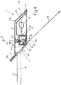
- Support 12 which provides for enabling rotation of light 4 about transverse axis 31 (Fig.5), and rotation of housing 13a (including reflector 15) about longitudinal axis 32 (Fig.4), will now be described with reference to Fig.s 4 to 8.
- Support 12 consists of two halves made of electrically conductive material (e.g. aluminium) for defining conductive paths from the ends of rods 8 to a body 33 supporting bulb 16 and extending through wall 22 of body 13 and into front compartment 24, between wall 22 and reflector 15.
- Supporting body 33 is fitted to support 12 by means of two screws 34 (Fig.s 5 and 6) which also provide for ensuring electrical contact between the two halves of support 12 and the inside of supporting body 33. In view of the current carrying function of the two halves of support 12, these are separated and totally insulated by an insulating body 35.
- support 12 comprises two aligned arms 38 defining rotation axis 31.
- Each arm 38 terminates at one end in a wider head 39 projecting from housing 13a and defining an axial recess (shown by the dotted line in Fig.5) engaged by a pin (shown schematically by 4c in Fig.3) integral with the ends of rods 8 for enabling rotation of support 12 about axis 31 in known manner.
- arms 38 are integral with respective wider portions 41a shaped so as to form, together, a shield type body 41 (Fig.s 6 and 9-11) housed in the gap defined by slots 20 between walls 22 and 23 on housing 13a.
- Body 41 is integral with a pivot pin 43 extending through an opening in wall 23 into rear compartment 25.
- Pivot pin 43 also consists of two halves 43a integral with respective wider portions 41a and extending perpendicularly in relation to arms 38.
- Pin 43 which presents a wider retaining end portion 44 also consisting of two halves 44a, is housed in rotary manner inside seat 29 on cover 14.
- seat 29 comprises a projection 46 formed on the surface of cover portion 14b facing body 13; and a bracket 47 screwed to projection 46 by means of screws 48.
- Projection 46 and bracket 47 combine to define a cylindrical hole 49 having the same diameter as pin 43 and housing pin 43 so as to enable it to rotate in relation to its axis defining rotation axis 32.
- body 33 supporting the bulb is first fitted to wider portions 41a of support 12 by means of screws 34, so as to render the two halves of support 12 integral with each other (with insulating body 35 in between).
- Support 12 is then fitted to cover 14, by inserting it in the half hole defined by projection 46 and securing the bracket by means of screws 48.
- the cover is then fitted and screwed on to body 13, reflector 15 is fitted on, and light 4, so completed, is fitted on to the ends of rods 8.
- Support 12 thus enables light 4 to rotate, not only about transverse axis 31, as on the known lamp, but also about longitudinal axis 32, as shown in Fig.s 9 to 11.
- light 4, and consequently the light beam is adjusted about longitudinal axis 32 by rotating housing 13a (together with reflector 15), while support 12 and bulb 16 remain fixed in relation to rods 8.
- oscillating support 12 provides for adjusting light 4 and so directing the beam of bulb 16 as required, while at the same time maintaining current supply via the structure with no wiring required.
- Support 12 in fact provides for ensuring electrical continuity between structure 3 and bulb supporting body 33, as well as for insulating the supply and return paths.
- the hinging of support 12 to cover 14 as described above enables light 4 to be adjusted easily, while at the same time providing for sufficient friction for maintaining light 4 in the set position.
Landscapes
- Engineering & Computer Science (AREA)
- General Engineering & Computer Science (AREA)
- Fastening Of Light Sources Or Lamp Holders (AREA)
- Vessels And Coating Films For Discharge Lamps (AREA)
- Non-Portable Lighting Devices Or Systems Thereof (AREA)
Abstract

Description
- The present invention relates to a lamp, particularly a table lamp.
- In particular, the present invention relates to an improvement to the "Tizio" lamp (registered trade mark) manufactured by the present Applicant.
- The "Tizio" lamp is known to comprise a base housing a transformer, an articulated extendible arm structure, and a light supported on the articulated structure. The articulated structure in turn consists of three pairs of rods, of which a first pair is fitted to the base, a second pair pivots on the first, about a third of the way along its length, and a third pair pivots on the second, also about a third of the way along its length. The ends of the third pair of rods furthest from the point at which it pivots on the second pair define hinges for the light, to enable this to be raised, lowered and rotated about an axis which, in use, is substantially horizontal. On the above lamp, the current for the light is supplied along the lamp structure, for eliminating unsightly wiring or wire concealing means.
- In view of the success of the above lamp, it has been decided to improve it even further for rendering it even more adaptable to the environment by enabling the beam to be directed as required.
- It is an object of the present invention to provide a lamp, particularly a table lamp of the aforementioned type, enabling troublefree direction of the light beam as required.
- According to the present invention, there is provided a lamp, particularly a table lamp, comprising: a base; a load-bearing structure fitted to said base and defining a path along which power is conducted; and a light supported on said structure, said light including a housing and a support located between said structure and said housing and designed to enable rotation of said housing about a first axis, and to ensure electrical continuity between said structure and a bulb fitted to said support; characterised by the fact that said support comprises means enabling rotation of said housing about a second axis perpendicular to the first. A preferred non-limiting embodiment of the present invention will be described by way of example with reference to the accompanying drawings, in which:
- Fig.1 shows an overall side view of the lamp according to the present invention;
- Fig.2 shows a larger-scale side view of the light portion of the Fig.1 lamp;
- Fig.3 shows a top plan view of the Fig.2 light;
- Fig.4 shows a longitudinal section of the light along line IV-IV in Fig.3;
- Fig.5 shows an exploded top plan view of the light;
-
Fig.s -
Fig.s - As shown in Fig.1, the lamp according to the present invention and indicated as a whole by 1 comprises a base 2 (housing a transformer and electronic voltage and brightness adjuster); a load-
bearing structure 3; and alight 4. In more detail, saidstructure 3 comprises three pairs of articulated rods (in Fig.1, only one rod in each pair is shown): a first pair ofrods 5 extending vertically and fitted to either side ofbase 2; a second pair ofrods 6 pivoting on said first pair ofrods 5 atpoint 7 roughly a third of the way along its length; and a third pair ofrods 8 pivoting on said second pair ofrods 6 at point 9 roughly a third of the way along its length. The free ends ofrods points 7 and 9 are provided withcounterweights rods 8 opposite those fitted withcounterweights 11, means are provided for rotating light 4 about two perpendicular axes, as described in detail with reference to Fig.s 2-11.Structure 3 is employed in known manner for supplying current to the bulb by defining a conductive path betweenbase 2 andlight 4. - As shown in Fig.s 2 to 4,
light 4 comprises: an oscillatingsupport 12 connected mechanically and electrically tostructure 3; a substantially prismatic-shapedhousing 13a fitted to support 12 and consisting of a shapedbody 13 partially closed by acover 14; and a reflectingbody 15 integral withhousing 13a and enclosing, on three sides, abulb 16 connectable to support 12. - As shown in the Fig.2 side view,
housing 13a, the external design of which is substantially the same as that of the aforementioned "Tizio" lamp, is shaped in the form of a parallelogram, one of the two oblique sides of which is continued in the form of an outwardly-projectingtab portion 17.Shaped body 13 defines a shell with a C-shaped cross section, open on the ideal surface corresponding to the oblique side of the parallelogram aligned withtab portion 17, and on the ideal base surface not adjacent toportion 17.Shaped body 13 is also divided ideally into twoportions base side 21 ofbody 13 adjacent totab portion 17. Said center portion is the sole connecting point betweenportions Shaped body 13 also presents parallelintermediate partition walls slots 20 and dividing the inside ofhousing 13a into two compartments separated by an intermediate gap and referred to, for the sake of simplicity, asfront compartment 24 andrear compartment 25.Front compartment 24 houses reflector 15 andbulb 16;rear compartment 25 houses part ofsupport 12; and the intermediate gap (corresponding to slots 20), which enableshousing 13a to oscillate in relation to support 12, as shown later on, houses another portion ofsupport 12.Front compartment 24, which is open on one side, presents means 26 for connection toreflector 15, which in turn presents means 26a for connection to cover 14 (Fig.5), and is shaped substantially in the form of a dish similar toportion 18 of shapedbody 13.Rear compartment 25, on the other hand, is fully closed bycover 14, which presents aportion 14a extending along the ideal oblique surface, and aportion 14b extending along part of the ideal base surface ofbody 13, so as to partially close the bottom ofslots 20.Cover 14, which is fitted tobody 13 by insertingend 14c into tab portion 17 (Fig.4) and by means of screws 27 (Fig.9) throughcover 14 andwall 22, also defines internal connectingmeans 28a for asafety rod 28 projecting outwards ofrear compartment 25, and ahinge seat 29 forsupport 12, as described in more detail later on. Finally,base side 21 ofbody 13 definesventilation holes 30. -
Support 12, which provides for enabling rotation oflight 4 about transverse axis 31 (Fig.5), and rotation ofhousing 13a (including reflector 15) about longitudinal axis 32 (Fig.4), will now be described with reference to Fig.s 4 to 8.Support 12 consists of two halves made of electrically conductive material (e.g. aluminium) for defining conductive paths from the ends ofrods 8 to abody 33 supportingbulb 16 and extending throughwall 22 ofbody 13 and intofront compartment 24, betweenwall 22 andreflector 15. Supportingbody 33 is fitted to support 12 by means of two screws 34 (Fig.s 5 and 6) which also provide for ensuring electrical contact between the two halves ofsupport 12 and the inside of supportingbody 33. In view of the current carrying function of the two halves ofsupport 12, these are separated and totally insulated by aninsulating body 35. - As shown in Fig.s 3 to 8,
support 12 comprises two alignedarms 38 definingrotation axis 31. Eacharm 38 terminates at one end in awider head 39 projecting fromhousing 13a and defining an axial recess (shown by the dotted line in Fig.5) engaged by a pin (shown schematically by 4c in Fig.3) integral with the ends ofrods 8 for enabling rotation ofsupport 12 aboutaxis 31 in known manner. - The opposite ends of
arms 38 are integral with respectivewider portions 41a shaped so as to form, together, a shield type body 41 (Fig.s 6 and 9-11) housed in the gap defined byslots 20 betweenwalls housing 13a.Body 41 is integral with apivot pin 43 extending through an opening inwall 23 intorear compartment 25.Pivot pin 43 also consists of twohalves 43a integral with respectivewider portions 41a and extending perpendicularly in relation toarms 38.Pin 43, which presents a widerretaining end portion 44 also consisting of twohalves 44a, is housed in rotary manner insideseat 29 oncover 14. In more detail,seat 29 comprises aprojection 46 formed on the surface ofcover portion 14b facing body 13; and abracket 47 screwed toprojection 46 by means ofscrews 48.Projection 46 andbracket 47 combine to define acylindrical hole 49 having the same diameter aspin 43 andhousing pin 43 so as to enable it to rotate in relation to its axis definingrotation axis 32. - During assembly,
body 33 supporting the bulb is first fitted towider portions 41a ofsupport 12 by means ofscrews 34, so as to render the two halves ofsupport 12 integral with each other (withinsulating body 35 in between).Support 12 is then fitted to cover 14, by inserting it in the half hole defined byprojection 46 and securing the bracket by means ofscrews 48. The cover is then fitted and screwed on tobody 13,reflector 15 is fitted on, andlight 4, so completed, is fitted on to the ends ofrods 8. -
Support 12 thus enableslight 4 to rotate, not only abouttransverse axis 31, as on the known lamp, but also aboutlongitudinal axis 32, as shown in Fig.s 9 to 11. In particular,light 4, and consequently the light beam, is adjusted aboutlongitudinal axis 32 by rotatinghousing 13a (together with reflector 15), while support 12 andbulb 16 remain fixed in relation torods 8. The advantages of the lamp according to the present invention will be clear from the foregoing description. In particular,oscillating support 12 provides for adjustinglight 4 and so directing the beam ofbulb 16 as required, while at the same time maintaining current supply via the structure with no wiring required.Support 12 in fact provides for ensuring electrical continuity betweenstructure 3 andbulb supporting body 33, as well as for insulating the supply and return paths. - The hinging of
support 12 to cover 14 as described above enableslight 4 to be adjusted easily, while at the same time providing for sufficient friction for maintaininglight 4 in the set position.
Claims (9)
- A lamp (1), particularly a table lamp, comprising: a base (2); a load-bearing structure (3) fitted to said base (2) and defining a path along which power is conducted; and a light (4) supported on said structure (3), said light (4) including a housing (13a) and a support (12) located between said structure (3) and said housing (13a) and designed to enable rotation of said housing (13a) about a first axis (31), and to ensure electrical continuity between said structure (3) and a bulb (16) fitted to said support (12); characterised by the fact that said support (12) comprises means (43) enabling rotation of said housing (13a) about a second axis (32) perpendicular to the first (31).
- A lamp as claimed in Claim 1, characterised by the fact that said support (12) comprises two aligned arms (38) each defining, at a first end, means (39) for hinging said housing (13a) to said structure (3); and a pin (43) fitted to a second end of said arms (38), extending perpendicularly to said arms (38), and housed in rotary manner in said housing (13a); said arms (38) defining said first axis or rotation (31), and said pin (43) defining said second axis of rotation (32).
- A lamp as claimed in Claim 2, characterised by the fact that said housing (13a) presents an elongated prismatic shape extending parallel to said second axis of rotation (32); said arms (38) extending crosswise in relation to said elongated prismatic shape.
- A lamp as claimed in Claim 2 or 3, characterised by the fact that said pin (43) comprises two portions (43a) insulated electrically in relation to each other and formed in one piece with a respective arm (38).
- A lamp as claimed in Claim 2, 3 or 4, characterised by the fact that said housing (13a) presents an internal projection (46) having a through hole (49) housing and having the same diameter as said pin (43).
- A lamp as claimed in one of the foregoing Claims from 2 to 5, characterised by the fact that each of said arms (38) presents, at said second end, a flat wider portion (41a) from which extends a respective portion (43a) of said pin (43); each said wider portion (41a) being fitted and electrically connected by means of screws (34) to a body (33) supporting said bulb (16).
- A lamp as claimed in one of the foregoing Claims from 2 to 6, characterised by the fact that said housing (13a) presents two opposed, aligned, transverse slots (20) housing said arms (38) for adjusting said housing (13a); said first end (39) of said arms (38) projecting outwards of said slots (20).
- A lamp as claimed in Claim 7, characterised by the fact that said housing (13a) presents two intermediate transverse walls (22, 23) extending on either side of said slots (20) and dividing said housing (13a) into a first and second compartment (25, 24) mutually separated by said slots (20); said first compartment (25) being closed on all sides and housing said pin (43) in rotary manner; and said second compartment (24) being open on one side and housing a reflector (15) and said body (33) supporting said bulb (16); said supporting body (33) being fitted through one (22) of said walls (22, 23) and to said support (12).
- A lamp as claimed in Claim 8, characterised by the fact that said housing (13a) comprises a shaped body (13) in the form of a parallelogram, when viewed laterally, with its base side and one oblique side open; and a cover (14) extending along said oblique side and closing said first compartment (25); said cover (14) having a projection (46) cooperating with a bracket (47) fitted to said projection (46) by means of screws (48); said projection (46) and said bracket (47) defining for said pin (43) a cylindrical seat (29) parallel to the open base side of said body (13); said pin (43) defining a wider retaining end portion (44) projecting from said cylindrical seat (29) on the opposite side in relation to said flat wider portion (41a) of said arms (38).
Applications Claiming Priority (2)
| Application Number | Priority Date | Filing Date | Title |
|---|---|---|---|
| IT53229U IT220599Z2 (en) | 1990-09-11 | 1990-09-11 | LAMP, IN PARTICULAR TABLE LAMP |
| IT5322990U | 1990-09-11 |
Publications (3)
| Publication Number | Publication Date |
|---|---|
| EP0475323A2 true EP0475323A2 (en) | 1992-03-18 |
| EP0475323A3 EP0475323A3 (en) | 1992-04-22 |
| EP0475323B1 EP0475323B1 (en) | 1995-12-27 |
Family
ID=11281045
Family Applications (1)
| Application Number | Title | Priority Date | Filing Date |
|---|---|---|---|
| EP91115210A Expired - Lifetime EP0475323B1 (en) | 1990-09-11 | 1991-09-09 | Lamp, particularly a table lamp |
Country Status (8)
| Country | Link |
|---|---|
| US (1) | US5235500A (en) |
| EP (1) | EP0475323B1 (en) |
| JP (1) | JPH04341702A (en) |
| KR (1) | KR920007065A (en) |
| AT (1) | ATE132241T1 (en) |
| DE (1) | DE69115804T2 (en) |
| ES (1) | ES2084075T3 (en) |
| IT (1) | IT220599Z2 (en) |
Cited By (2)
| Publication number | Priority date | Publication date | Assignee | Title |
|---|---|---|---|---|
| GB2355061A (en) * | 1999-09-17 | 2001-04-11 | Kazuhiro Yamanaka | A lamp constructed from electrically conducting elements |
| FR2872062A1 (en) * | 2004-06-25 | 2005-12-30 | Jacques Yves Mistretta | Device for bio-dynamising all forms of molecules going into pharmaceutical and/or industrial products, comprises a ramp or structure made of a stand, a side axis and an arm, and a moveable box |
Families Citing this family (13)
| Publication number | Priority date | Publication date | Assignee | Title |
|---|---|---|---|---|
| US6394634B2 (en) | 2000-02-28 | 2002-05-28 | Lawrence C. Kitchin | Manually adjustable boat light |
| US6866403B1 (en) | 2003-04-24 | 2005-03-15 | Adesso Inc. | Lipstick lamp |
| US7131843B1 (en) | 2004-12-03 | 2006-11-07 | Lucesco Lighting, Inc. | Joint system |
| US20060120092A1 (en) * | 2004-12-03 | 2006-06-08 | Richard Sapper | Lighting system |
| US8162502B1 (en) * | 2009-05-27 | 2012-04-24 | Zlatko Zadro | Illuminated continuously rotatable dual magnification mirror |
| US20110182063A1 (en) * | 2010-01-26 | 2011-07-28 | Habitex Corporation | Table Lamp |
| US20110310627A1 (en) * | 2010-06-18 | 2011-12-22 | Ching-Long Liang | Positioning structure for a table lampl |
| US20130286652A1 (en) * | 2012-04-26 | 2013-10-31 | Davinci Industrial Inc. | Table lamp |
| US8915629B2 (en) | 2012-12-19 | 2014-12-23 | Hussmann Corporation | Light fixture for a merchandiser |
| USD768282S1 (en) * | 2015-05-27 | 2016-10-04 | Alva Alta Lda | Structural support for solar envelope and solar collector |
| USD950118S1 (en) | 2018-10-15 | 2022-04-26 | Aylo, Llc | Light |
| US10935231B2 (en) | 2018-10-15 | 2021-03-02 | Aylo Llc | Systems and methods for a mirror mounted light with mobile device mounting |
| USD899226S1 (en) | 2019-09-09 | 2020-10-20 | Aylo Llc | Suction cup mount |
Citations (3)
| Publication number | Priority date | Publication date | Assignee | Title |
|---|---|---|---|---|
| EP0156290A2 (en) * | 1984-03-30 | 1985-10-02 | Patent-Treuhand-Gesellschaft für elektrische Glühlampen mbH | Lighting device with swingable lighting head |
| DE3611311A1 (en) * | 1986-04-04 | 1987-10-08 | Hartmut S Engel | ADJUSTABLE LAMP |
| EP0351792A2 (en) * | 1988-07-19 | 1990-01-24 | Artemide Sidecar S.R.L. | Table lamp |
Family Cites Families (3)
| Publication number | Priority date | Publication date | Assignee | Title |
|---|---|---|---|---|
| US2280402A (en) * | 1939-08-10 | 1942-04-21 | Wilmot Castle Co | Dental operating lamp |
| US3790773A (en) * | 1971-10-04 | 1974-02-05 | R Sapper | Lamp with an articulated support |
| US4494177A (en) * | 1983-04-20 | 1985-01-15 | Plan Hold Corp. | Articulated task lamp |
-
1990
- 1990-09-11 IT IT53229U patent/IT220599Z2/en active IP Right Grant
-
1991
- 1991-09-09 EP EP91115210A patent/EP0475323B1/en not_active Expired - Lifetime
- 1991-09-09 DE DE69115804T patent/DE69115804T2/en not_active Expired - Fee Related
- 1991-09-09 US US07/756,466 patent/US5235500A/en not_active Expired - Fee Related
- 1991-09-09 AT AT91115210T patent/ATE132241T1/en not_active IP Right Cessation
- 1991-09-09 ES ES91115210T patent/ES2084075T3/en not_active Expired - Lifetime
- 1991-09-10 KR KR1019910015785A patent/KR920007065A/en not_active Application Discontinuation
- 1991-09-11 JP JP3308570A patent/JPH04341702A/en active Pending
Patent Citations (3)
| Publication number | Priority date | Publication date | Assignee | Title |
|---|---|---|---|---|
| EP0156290A2 (en) * | 1984-03-30 | 1985-10-02 | Patent-Treuhand-Gesellschaft für elektrische Glühlampen mbH | Lighting device with swingable lighting head |
| DE3611311A1 (en) * | 1986-04-04 | 1987-10-08 | Hartmut S Engel | ADJUSTABLE LAMP |
| EP0351792A2 (en) * | 1988-07-19 | 1990-01-24 | Artemide Sidecar S.R.L. | Table lamp |
Cited By (2)
| Publication number | Priority date | Publication date | Assignee | Title |
|---|---|---|---|---|
| GB2355061A (en) * | 1999-09-17 | 2001-04-11 | Kazuhiro Yamanaka | A lamp constructed from electrically conducting elements |
| FR2872062A1 (en) * | 2004-06-25 | 2005-12-30 | Jacques Yves Mistretta | Device for bio-dynamising all forms of molecules going into pharmaceutical and/or industrial products, comprises a ramp or structure made of a stand, a side axis and an arm, and a moveable box |
Also Published As
| Publication number | Publication date |
|---|---|
| US5235500A (en) | 1993-08-10 |
| IT9053229V0 (en) | 1990-09-11 |
| IT9053229U1 (en) | 1992-03-11 |
| DE69115804D1 (en) | 1996-02-08 |
| JPH04341702A (en) | 1992-11-27 |
| ES2084075T3 (en) | 1996-05-01 |
| EP0475323B1 (en) | 1995-12-27 |
| DE69115804T2 (en) | 1996-07-04 |
| EP0475323A3 (en) | 1992-04-22 |
| KR920007065A (en) | 1992-04-28 |
| ATE132241T1 (en) | 1996-01-15 |
| IT220599Z2 (en) | 1993-10-06 |
Similar Documents
| Publication | Publication Date | Title |
|---|---|---|
| EP0475323B1 (en) | Lamp, particularly a table lamp | |
| US4776809A (en) | Low voltage distribution system with two-conductor track | |
| EP0326739B1 (en) | Wall-mounted over-bed lighting fixture | |
| US5541822A (en) | Flashlight with pivoting head | |
| US6007222A (en) | Modular exterior rearview mirror assembly | |
| US6146003A (en) | Modular exterior rearview mirror assembly | |
| US5130914A (en) | Light fixture assembly | |
| KR930008816B1 (en) | Headlight for car | |
| US5295845A (en) | Combined power plug | |
| US4699439A (en) | Track lighting adapter | |
| US4916596A (en) | Convertible flashlight | |
| ES2288148T5 (en) | AUTOMOBILE VEHICLE HEADLIGHT EQUIPPED WITH A DOWNLOAD LAMP AND PERFECTED ELECTROMAGNETIC SHIELDING MEDIA. | |
| CN1759285A (en) | Refrigerator with internal lighting | |
| GB2341228A (en) | Combined incandescent/fluorescent lantern with pivoting lighting arms | |
| US5420764A (en) | Socket/tab supported light fixture | |
| US2099020A (en) | Wiremold lumiline reflector | |
| US4999756A (en) | Desk lamp with adjustable lights | |
| AU690365B2 (en) | Lighting device | |
| JP2537264Y2 (en) | Spotlight | |
| US6093051A (en) | Light fixture conductors and methods of assembly | |
| JP4300659B2 (en) | Lighting fixtures and desk lamps | |
| CN116265842A (en) | Refrigerator with a refrigerator body | |
| GB2220307A (en) | "Articulated support for a lamp or the like" | |
| JPH1196814A (en) | Lighting system | |
| KR200162321Y1 (en) | Hinge bracket for microwave oven |
Legal Events
| Date | Code | Title | Description |
|---|---|---|---|
| PUAI | Public reference made under article 153(3) epc to a published international application that has entered the european phase |
Free format text: ORIGINAL CODE: 0009012 |
|
| PUAL | Search report despatched |
Free format text: ORIGINAL CODE: 0009013 |
|
| AK | Designated contracting states |
Kind code of ref document: A2 Designated state(s): AT BE CH DE ES FR GB IT LI |
|
| AK | Designated contracting states |
Kind code of ref document: A3 Designated state(s): AT BE CH DE ES FR GB IT LI |
|
| 17P | Request for examination filed |
Effective date: 19920924 |
|
| 17Q | First examination report despatched |
Effective date: 19940428 |
|
| RAP1 | Party data changed (applicant data changed or rights of an application transferred) |
Owner name: ARTEMIDE S.P.A. |
|
| GRAA | (expected) grant |
Free format text: ORIGINAL CODE: 0009210 |
|
| AK | Designated contracting states |
Kind code of ref document: B1 Designated state(s): AT BE CH DE ES FR GB IT LI |
|
| REF | Corresponds to: |
Ref document number: 132241 Country of ref document: AT Date of ref document: 19960115 Kind code of ref document: T |
|
| ITF | It: translation for a ep patent filed |
Owner name: STUDIO TORTA SOCIETA' SEMPLICE |
|
| REF | Corresponds to: |
Ref document number: 69115804 Country of ref document: DE Date of ref document: 19960208 |
|
| ET | Fr: translation filed | ||
| REG | Reference to a national code |
Ref country code: CH Ref legal event code: NV Representative=s name: ISLER & PEDRAZZINI AG PATENTANWAELTE |
|
| REG | Reference to a national code |
Ref country code: ES Ref legal event code: FG2A Ref document number: 2084075 Country of ref document: ES Kind code of ref document: T3 |
|
| PG25 | Lapsed in a contracting state [announced via postgrant information from national office to epo] |
Ref country code: GB Effective date: 19960909 Ref country code: AT Effective date: 19960909 |
|
| PG25 | Lapsed in a contracting state [announced via postgrant information from national office to epo] |
Ref country code: ES Free format text: LAPSE BECAUSE OF NON-PAYMENT OF DUE FEES Effective date: 19960910 |
|
| PG25 | Lapsed in a contracting state [announced via postgrant information from national office to epo] |
Ref country code: BE Effective date: 19960930 |
|
| PLBE | No opposition filed within time limit |
Free format text: ORIGINAL CODE: 0009261 |
|
| STAA | Information on the status of an ep patent application or granted ep patent |
Free format text: STATUS: NO OPPOSITION FILED WITHIN TIME LIMIT |
|
| 26N | No opposition filed | ||
| BERE | Be: lapsed |
Owner name: ARTEMIDE S.P.A. Effective date: 19960930 |
|
| GBPC | Gb: european patent ceased through non-payment of renewal fee |
Effective date: 19960909 |
|
| PG25 | Lapsed in a contracting state [announced via postgrant information from national office to epo] |
Ref country code: FR Effective date: 19970630 |
|
| REG | Reference to a national code |
Ref country code: FR Ref legal event code: ST |
|
| REG | Reference to a national code |
Ref country code: FR Ref legal event code: ST |
|
| PGFP | Annual fee paid to national office [announced via postgrant information from national office to epo] |
Ref country code: CH Payment date: 20001004 Year of fee payment: 10 |
|
| PGFP | Annual fee paid to national office [announced via postgrant information from national office to epo] |
Ref country code: DE Payment date: 20001122 Year of fee payment: 10 |
|
| PG25 | Lapsed in a contracting state [announced via postgrant information from national office to epo] |
Ref country code: LI Free format text: LAPSE BECAUSE OF NON-PAYMENT OF DUE FEES Effective date: 20010930 Ref country code: CH Free format text: LAPSE BECAUSE OF NON-PAYMENT OF DUE FEES Effective date: 20010930 |
|
| PG25 | Lapsed in a contracting state [announced via postgrant information from national office to epo] |
Ref country code: DE Free format text: LAPSE BECAUSE OF NON-PAYMENT OF DUE FEES Effective date: 20020501 |
|
| REG | Reference to a national code |
Ref country code: CH Ref legal event code: PL |
|
| REG | Reference to a national code |
Ref country code: ES Ref legal event code: FD2A Effective date: 19971011 |
|
| PG25 | Lapsed in a contracting state [announced via postgrant information from national office to epo] |
Ref country code: IT Free format text: LAPSE BECAUSE OF NON-PAYMENT OF DUE FEES;WARNING: LAPSES OF ITALIAN PATENTS WITH EFFECTIVE DATE BEFORE 2007 MAY HAVE OCCURRED AT ANY TIME BEFORE 2007. THE CORRECT EFFECTIVE DATE MAY BE DIFFERENT FROM THE ONE RECORDED. Effective date: 20050909 |